Lyonsden Blog

Category - Amiga

How to access a network share on the Amiga

After getting it online this has to be the next best thing your can do with your Amiga. Being able to access a network share on the Amiga is really a liberating experience. It affords you not just the freedom to quickly access files you may have downloaded on your PC but also near unlimited extra storage for your Amiga. It’s quite a straightforward process and I’ll go through the whole thing from start to finish in this post.

Before going any further it’s assumed that you already have your Amiga networked and have configured a TCP/IP Stack as these are essential. You will also need a Windows based PC to create a shared folder on (or a suitable NAS that supports the SMB1).


Installing the Amiga Software

I’ll deal with the Amiga installation side of things first as that’s much more straightforward. To begin with you need to download two packages off Aminet, smbfs-68k.lha and SMBMounter.lha.

We only need a single file from the SMBFS package so simply extract the LHA archive to your RAM disk and then copy the ‘SMBFS’ file to your C: drive. (Strictly speaking if you are comfortable with the command line then this is all you need but we’re going to install a GUI for it, hence the need for SMBMounter).

Next extract the SMBMounter archive, run the installer and select ‘Intermediate User’ as shown below.
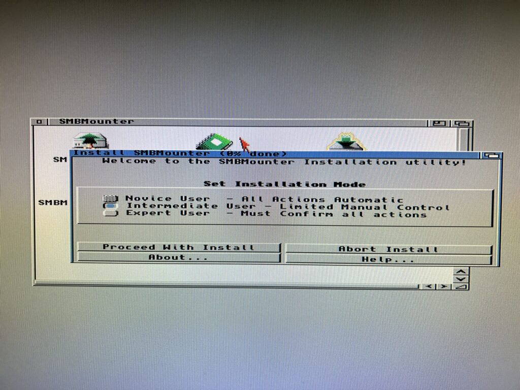
 

Installing SMBMounter

Installing SMBMounter


Select ‘Install for real’.
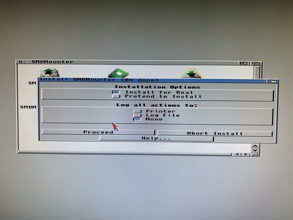
 

Installing SMBMounter

Installing SMBMounter


Choose where to install the software. It doesn’t really matter but in my case I selected my ‘Internet’ drawer as I like to keep all my internet/network related stuff in one place. Note that you do not need to create an SMBMounter drawer – one will be created automatically in the location you choose.
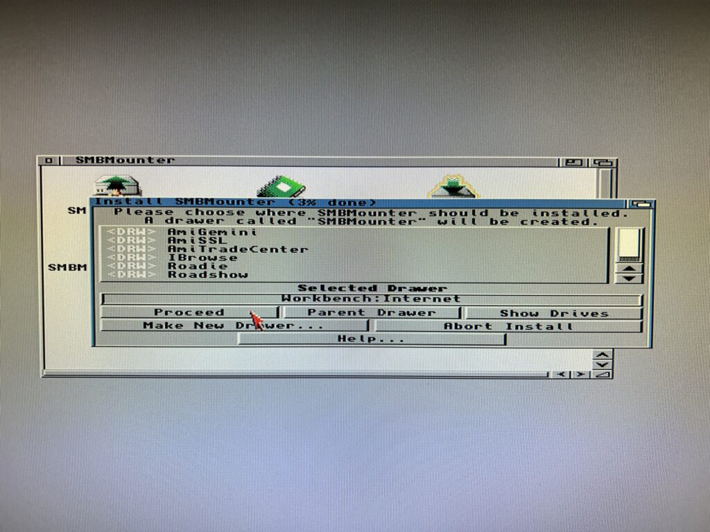
 

Installing SMBMounter

Installing SMBMounter


Next choose a language if English is not your native tongue.
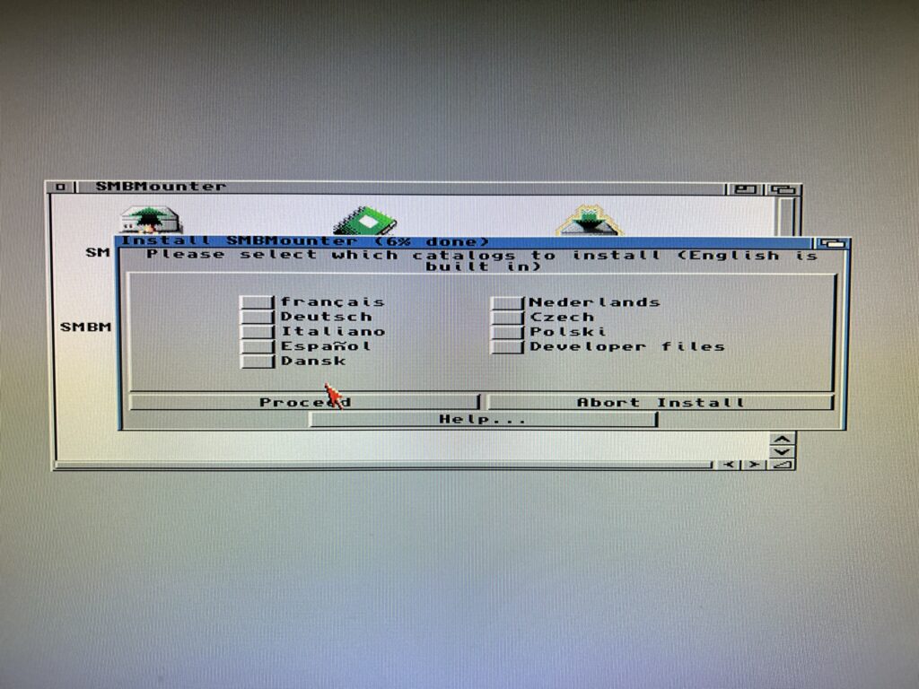
 

Installing SMBMounter

Installing SMBMounter


The final thing to choose is the icon set that will be used for the program files. I’m using OS3.2 and like GlowIcons so chose that option.
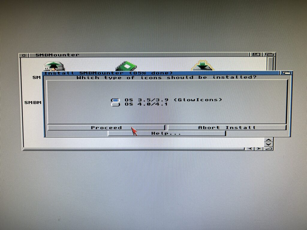
 

Installing SMBMounter

Installing SMBMounter


The program will now be installed. After a few seconds you should get an ‘Installation Complete’ message along with a reminder of the install location.
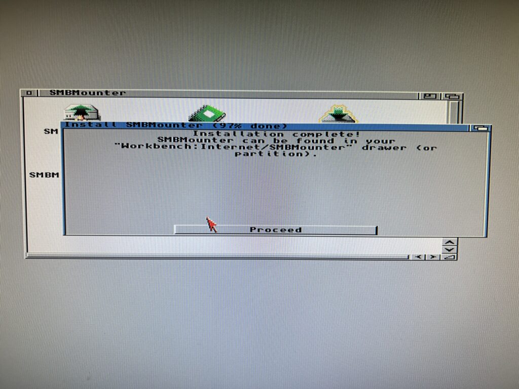
 

Installing SMBMounter

Installing SMBMounter


If everything went well you should have a drawer looking just like the one in the photo below.
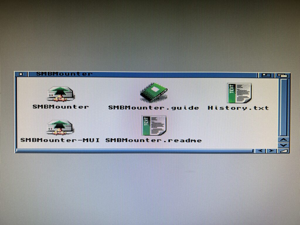
 

access a network share on the Amiga

Installing SMBMounter


That’s it for the Amiga side of things, at least for now anyway. Time to boot up your Windows PC and configure something for the Amiga to connect to!


Configuring an SMB1 Share on a PC


Enabling SMB1

I just want to preface this section by saying that I created this guide on a Windows 11 PC (which was upgraded from a Windows 10 install). It should work with older versions of Windows too. However Microsoft is actively trying to kill off SMB1 (see here) so if you are reading this in the future you may have a few extra hoops you need to jump through to get this working. (Alternatively just use an old PC running Windows 10!)

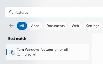
Right, with that out of the way the first thing you must do is determine whether your PC has SMB1 file sharing enabled, and if not, enable it. The easiest way to achieve this is to open the ‘Turn Windows features on or off’ control panel.
 

Turn Windows Features on or off

Turn Windows Features on or off


To do this use the start menu search facility and type ‘features’. Windows will have a rummage around the C: drive and then present you with the program so you can just click on it as shown above.
 

Turn Windows Features on or off

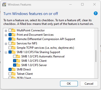
Checking that SMB1 client/server is enabled.


Scroll down the list until you get to the SMB section. You want to see little check boxes next to ‘SMB 1.0/CIFS Client’ and ‘SMB 1.0/CIFS Server’. If they aren’t ticked, click in the little boxes to enable them and then click on OK. You will have to restart Windows for it to complete the installation of the new features.

Please note you do NOT want to have a check mark next to ‘SMB 1.0/CIFS Automatic Removal’. If you do have it ticked this will cause Windows to remove SMB after a few weeks of the protocol not being utilised.


Creating a Local User Account

This part isn’t strictly necessary but I recommend it as it helps keep things neat and tidy and also prevents issues in the future should you change your PC account password. I’m doing this in Windows 11 Home. There are multiple ways to achieve this but I’m just going to describe one method which is very straightforward. If you already know how to do this then skip to the next section.

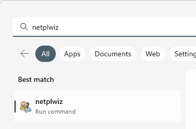
Firstly using the start menu search enter ”netplwiz’ and then run the program that Windows finds.
 

NETPLWIZ

Running NETPLWIZ to access user accounts.


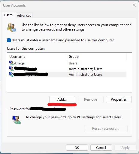
This will bring up the ‘User Accounts’ window. You should see at least one account here which will be your main Windows account. There may be others too, depending on how many people use the PC.
 

Windows 11 User Accounts

Windows 11 Local User Accounts window.


I had already created an Amiga account when I took the above screengrab but will pretend I didn’t for the rest of this section so click on ‘Add…’ to continue.
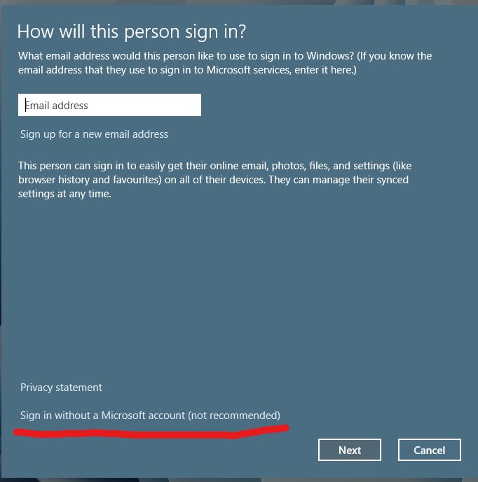
 

No I don’t want to create another Microsoft account…


Ignore Microsoft’s recommendation and click on the bit at the bottom which says ‘Sign in without a Microsoft account (not recommended) and then click ‘Next’.
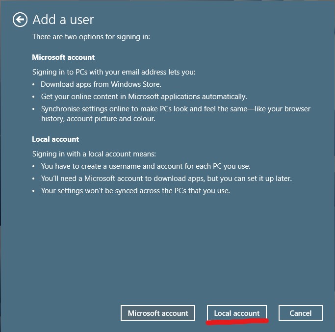
 

I just told you I don’t want one, take the hint!


Select the ‘Local account’ option from the bottom of the next window that appears…
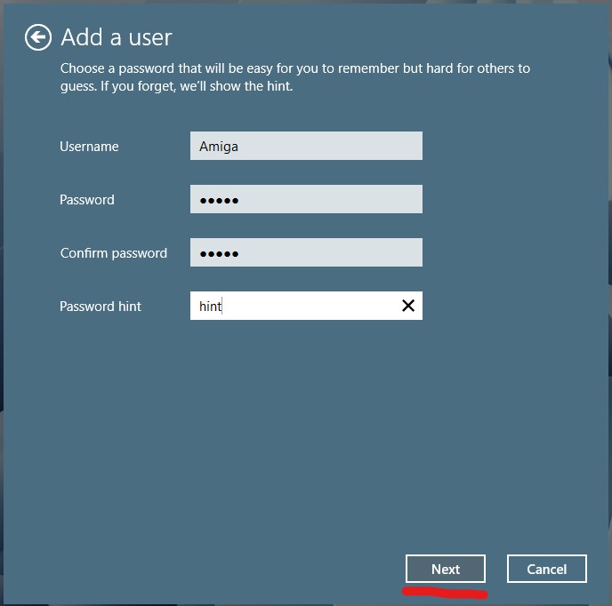
 

Microsoft finally took the hint and let me set up a local account.


Enter the name for your local account, ‘Amiga’ in my case, a password (twice) and a Password hint in case you forget it (this can’t be skipped unfortunately). Click on ‘Next’ when ready.
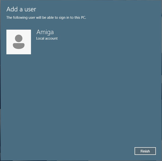
 

One local Amiga account all ready to go.


This will bring up a confirmation screen with the name of your account. Click ‘Finish’.
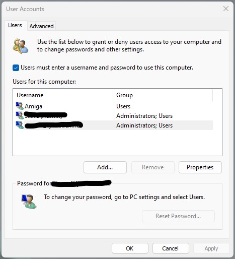
 

Mission accomplished.


This will bring you back to the User Account window (above) which you can now safely close by clicking on ‘OK’. Your local account is now created and ready to be used in the next section.


Creating a Shared Folder

With SMB1 enabled it’s now time to setup a shared folder that your Amiga can actually connect to. Choose a location with enough free space on your PC and create a new folder there. I chose my E: drive as it has plenty of free space but you can choose any location you want. Give it a suitable name.
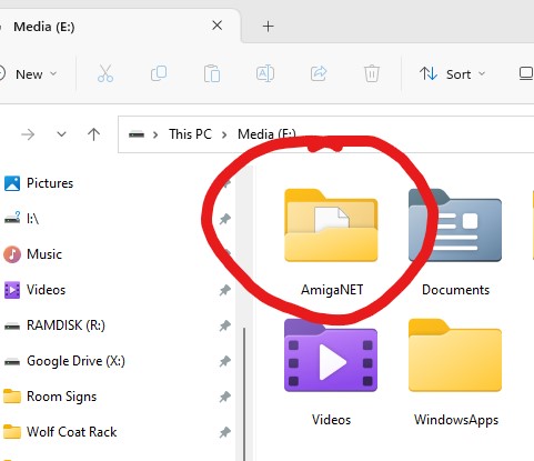
 

Creating a folder for our share.


Now we need to SHARE this folder so right-click on it and select ‘Properties’ and then ‘Advanced Sharing…’
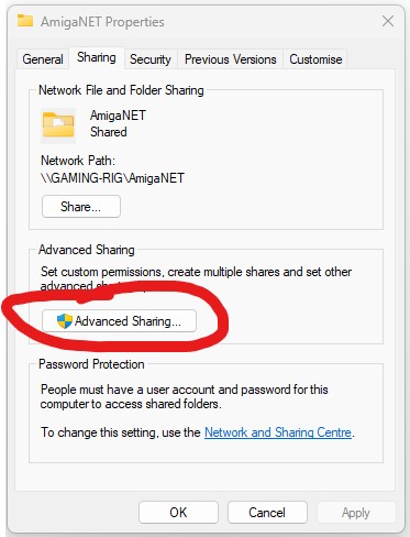
 

Selecting Advanced Sharing


Once the Advanced Sharing windows pops up you need to tick the box next to where it says ‘Share this folder’ and then give the share a name in the box below. Try to keep the name short and without spaces or punctuation to avoid any problems connecting to it down the line.
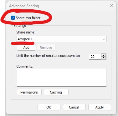
 

Enabling sharing and giving the share a name.


Before closing the Advanced Sharing window, click on the ‘Permissions’ button near the bottom.
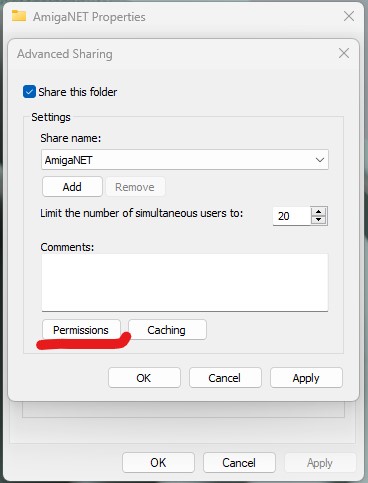
 

Click permissions.


A new window will pop up allowing you add a new user to access the shared folder. To do this click on ‘Add’.
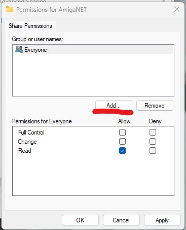
 

Click Add.


The will bring up yet another window where you can enter the account name of the user you want to access the share.

Enter the username into the box. My local user account was called ‘Amiga’ so I entered ‘Amiga’ in this box. You can click the ‘Check Names’ button on the right to make sure you have done this correctly. If you’ve made a mistake Windows will say ‘name not found’ which means it cannot find an account with that name. Time to check your spelling! Click on OK when done.
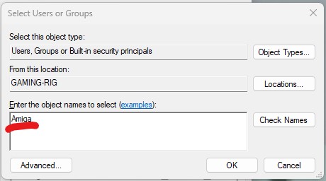
 

Add YOUR local user account name.


You will be back looking at the Share Permission window again now and you should see the username of the account you just added at the top of the list (see below). Make sure it is selected and then click the empty box next to ‘Full Control’ to grant your Amiga this permission, then click ‘Apply’ then ‘OK’..

By the way, if you are not aware of the name of your computer, you will see it here. It’s the name in the brackets before the backslash (GAMING-RIG in my case) – jot it down as you will need it later!
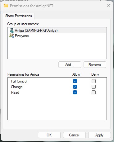
 

Giving your local account full control of the share.


You should end up with a window looking like the one above. Click OK when you are happy everything looks correct and then on OK once more to get back to the main properties window as shown below. Were are nearly there now – just one last thing to do.

Click on the ‘Security’ tab (highlighted below).
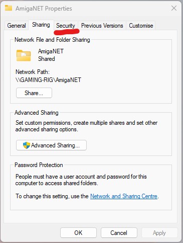
 

Select the Security tab.


Next click on the ‘Edit’ button…
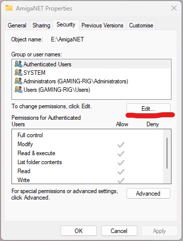
 

Click Edit.


Then click on the ‘Add’ button…
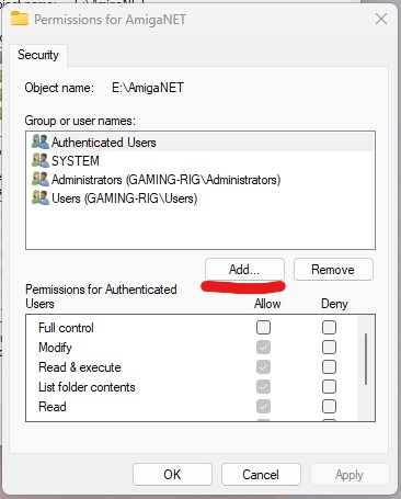
 

Click Add.


Then just as you did before, enter the same local account username into the box so we can define the permissions this user should have. Once done, click on OK.
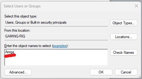
 

Enter YOUR local account name once more.


Back in the Permissions window make sure that the user is highlighted in the top section and then click on the box next to ‘Full Control’ to grant them full access to the share.
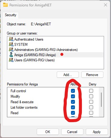
 

Ensure all the boxes are ticked.


Click on OK and then OK again. Congratulations, you have just created a shared folder on your PC and granted access to it from the local user account you created earlier. Time to get back to the Amiga!


Connecting to the Shared Folder from your Amiga


With the share created, a local account setup, SMBFS installed to C: and SMBMounter installed on your Amiga we are ready for the final piece of the puzzle; configuring SMBMounter.
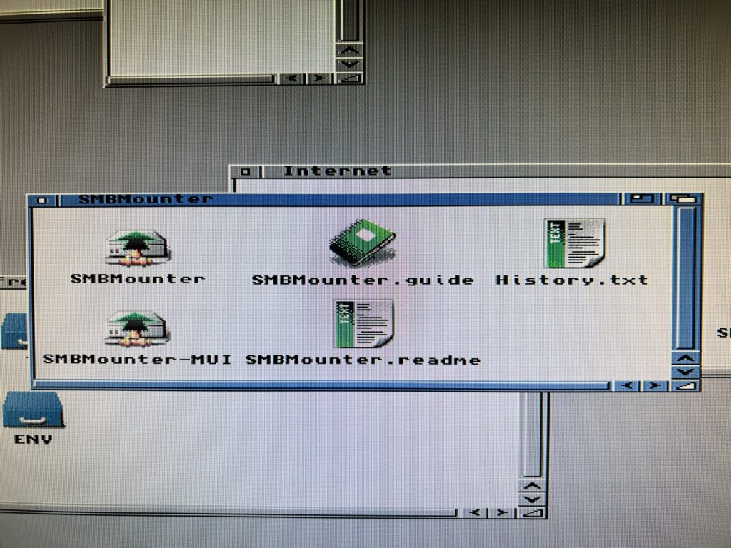
 

access a network share on the Amiga

Note the two different versions of SMBMounter (with and without MUI).


There are actually two versions of SMBMounter included, a regular one and one that utilises MUI. They both perform exactly the same functions but I prefer the layout of the MUI version so that’s what I’ll be using here.
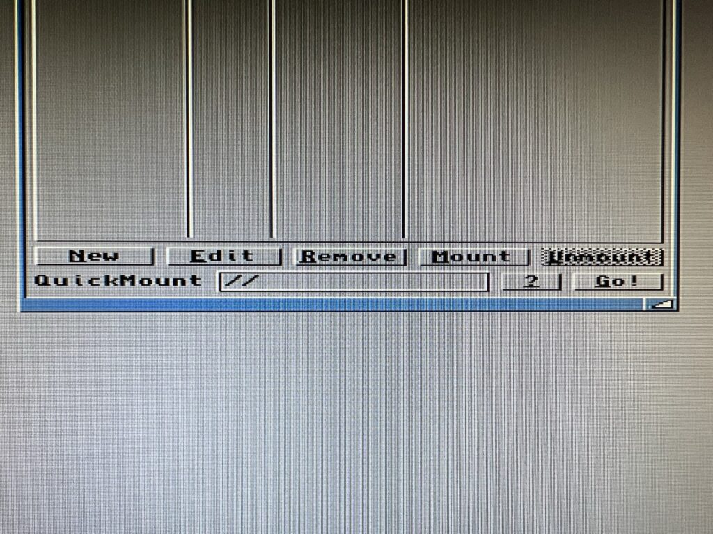
 

Use the ‘Remove’ button shown above to get rid of the supplied mount entries.


The program comes with a few mounts already configured but they are years out of date and no longer work so delete all of them before going any further to keep things neat and tidy. To delete them simply highlight each one in turn and click on the ‘Remove’ button (see photo above).
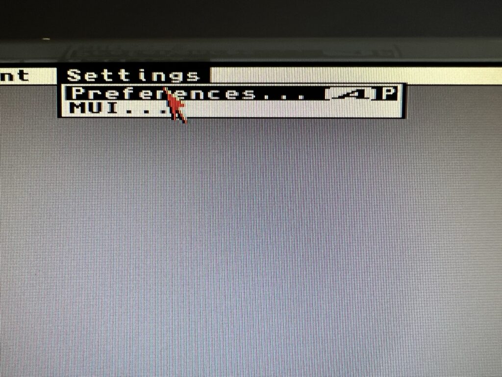
 

Preferences menu.


Next, open up the Preferences window (accessible from the menu – shown above) to configure a few parameters.

We haven’t bothered installing Samba but to prevent it from complaining I set the path here for it to ‘C:’. The path to SMBFS should be set to ‘C:smbfs’. Note you can browse to the location using the file browser icon on the right of each box if you prefer.
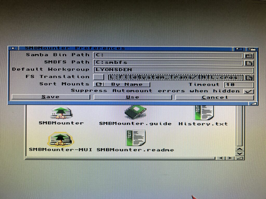
 

access a network share on the Amiga

Editing the preferences.


The default workgroup is actually set to ‘WORKGROUP’ and you can probably leave it as is. However I do actually have a workgroup configured on my network so I entered the name of it here; ‘LYONSDEN’. The rest of the settings can be left alone. Double check you have entered everything correctly and then click on ‘Save’ to have it remember your settings and move on.
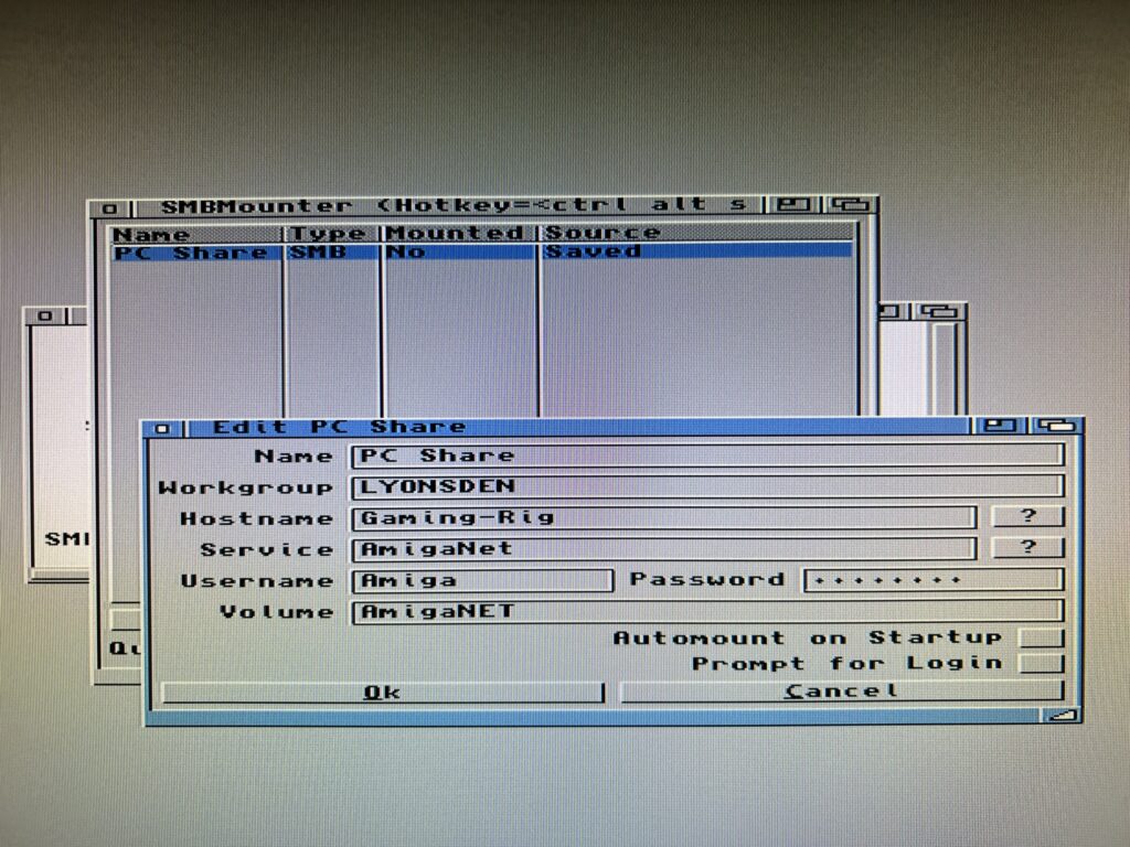
 

access a network share on the Amiga

Entering the settings for our share.


The final hurdle is to configure the connection to our shared folder. Click on ‘New’ and then enter the details of your share using the guidance below to help you.


SMBMounter Configuration
  • Name – this is an arbitrary label for the connection as it will appear in the SMBMounter list. (Like the connections it came with when you first installed it for example). I called mine ‘PC Share’ but you can call yours anything you want..
  • Workgroup – this will default to WORKGROUP and you can leave it like this but I entered the name of my own workgroup; ‘LYONSDEN’.
  • Hostname – this is the name of your PC, in my case ‘Gaming-Rig’. If you are unsure what it is refer back to the section in red where I told you to make a note of it during the ‘Creating a Shared Folder’ section.
  • Service – this is the name of the shared folder we created earlier, in my case ‘AmigaNet’.
  • Username – this is the name of the local user account we created earlier, in my case ‘Amiga’.
  • Password – the password we set for the local user account earlier.
  • Volume – this is the name you want the share to have on your Amiga. This is like naming your hard drives when you use HDToolbox. Whatever name you enter here is the name that will appear on workbench when the drive is mounted.
  • Automount at Start-up – self explanatory really. I leave this off as I don’t always want the share connected, especially if I just want to play some WHDLoad games for example.
  • Prompt for Login – this is an alternative to having the username and password stored and entered automatically. If ticked it will ask you to login with a username and password every time you want to connect. I leave this feature off as it’s would be a pain for me to do this all the time.


Once you’ve entered all the above details and checked they are all correct click on OK. Be sure to ‘Save all mounts’ from the Project menu before proceeding so you don’t lose all those settings when rebooting your Amiga.
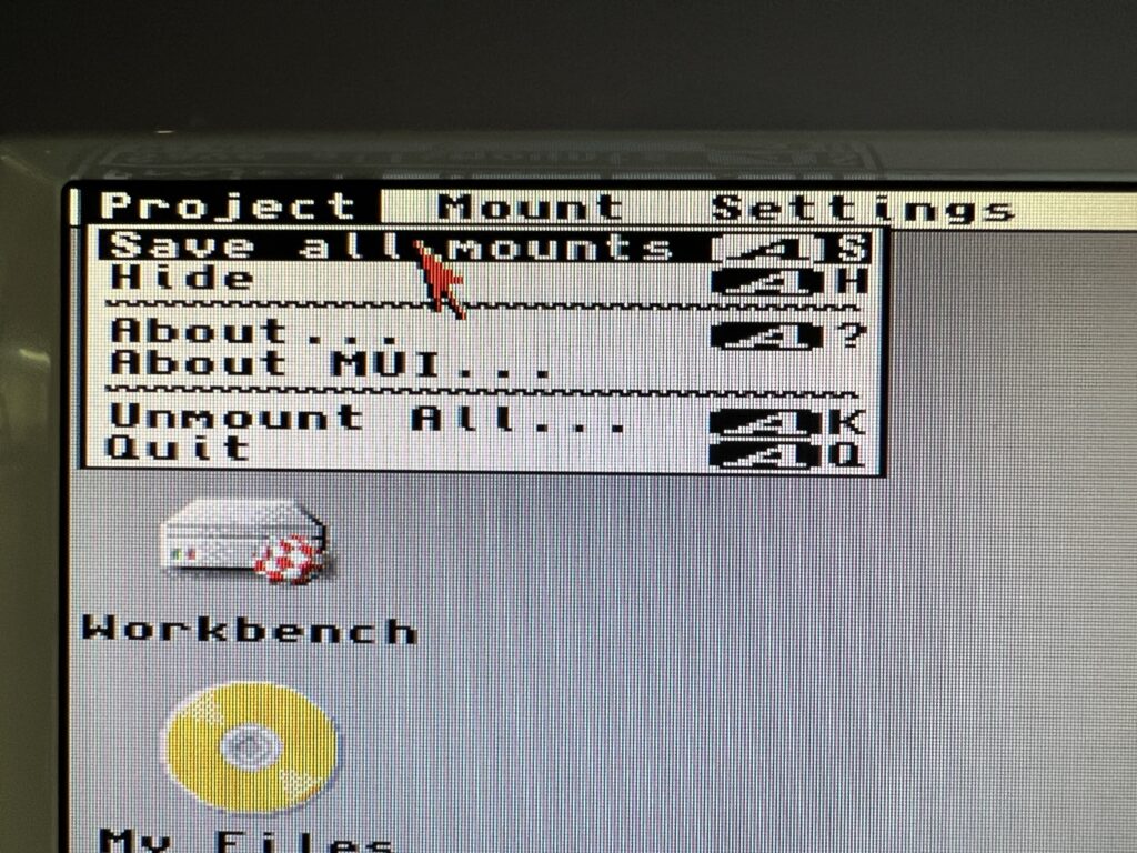
 

Saving your mount settings.


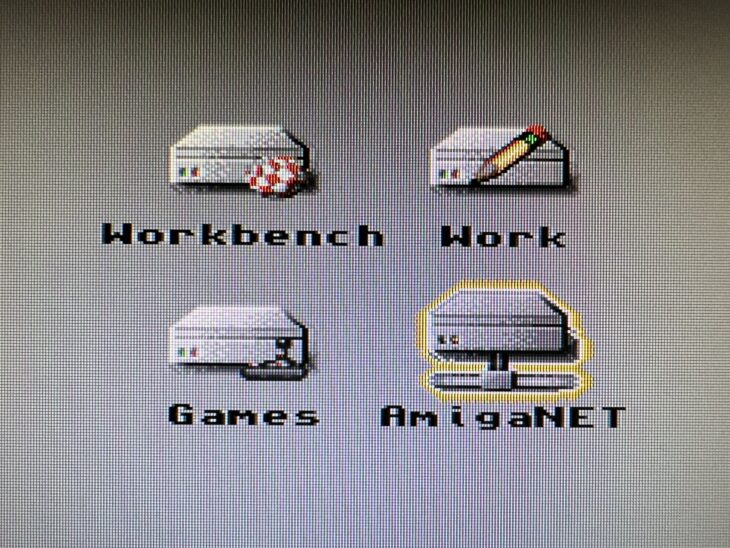
Now for the moment of truth! Click on the ‘Mount’ button in SMBMounter and if you’ve done everything correctly the share should appear on your Workbench after a couple of seconds. (Note – the icon that appears for you will differ depending on what icon packs and settings you are using).
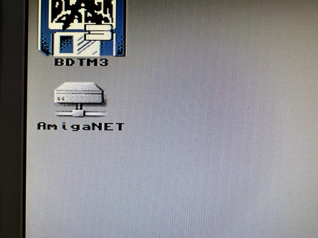
 

access a network share on the Amiga

Success – an icon like this on your Workbench means your share is connected!


You can use this drive just like you would any other. Drag and drop files into it, off it, delete them, save stuff there, even change the drive icon. It’s accessible from other programs just like a regular Amiga partition too so you can use it in Directory Opus, Wordworth or whatever other stuff you use.
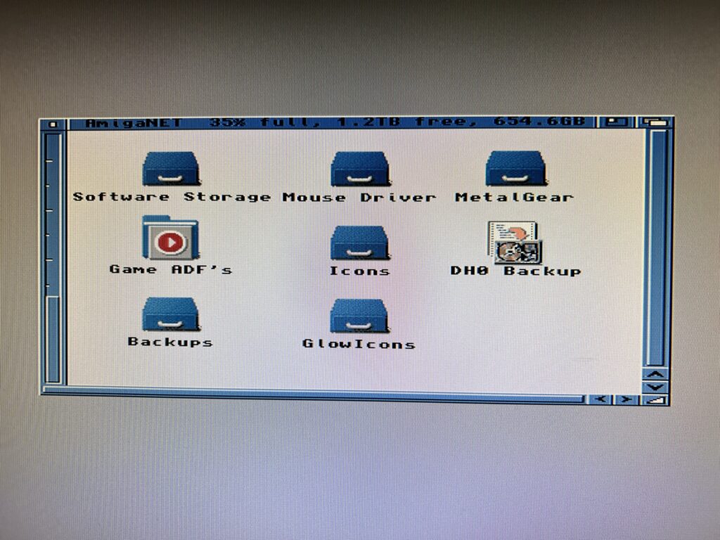
 

My SMB Share – 1.2Tb free!


As can be seen in the image above the Amiga is able to recognise the full capacity of the shared folder, that’s 1.2 Terabytes in my case – an insane amount of storage for any Amiga.

Quick Troubleshooting Tips

If you get any errors, such as ‘access denied’ or ‘incorrect username/password’ you will need to double check that you have entered the correct and IDENTICAL username and password in both SMBMounter and Windows. Likewise you might need to double check the name of the share in each and so on.

If you’ve done all that find that you cannot connect at all, or if one day in the future it all stops working then your firewall may well be to blame…


Firewalls

A real quick way to prove whether your firewall is at fault is to just disable it and try to connect again. If it works then you have found the problem – if not then at least you’ve ruled something out. Make sure you turn it back on after testing though!

Assuming your firewall is to blame, to fix the problem you are going to need to find a way to allow traffic to flow between your Amiga and PC. I’m afraid there’s no single magic bullet for this – there’s too many variables at play. All I can do is explain how I got around this problem myself. Networking is a pretty complex topic and well beyond the scope of this post to explain everything.

Anyway I use Norton 360 which has it’s own firewall (by default Windows 10/11 use Windows Defender) and it decided to block my Amiga from accessing my share after my Internet went down and my router rebooted. I couldn’t even ping my PC from my Amiga so I knew something wasn’t right.


Adding a trusted device in Norton 360’s Firewall settings.


Norton 360’s firewall allows you to add trusted devices that are allowed to connect to your PC irrespective of any other rules that may exist. To do this you must enter either the IP address of your Amiga or the MAC address of the network card you are using in it. This is probably the best method for most users as the MAC address of the card will never change and it is easy to find. Most cards will have their MAC address displayed on a label affixed to them somewhere. Finding out your Amiga’s IP address is not always so straightforward and unless you possess the knowledge of how to make it static you are going to keep having this issue over and over. Why? Because the IP will change frequently and your firewall will no longer know it should be trusted.
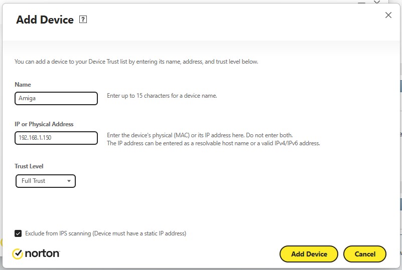
 

Adding a trusted device in Norton 360’s Firewall settings.


As I knew what my Amiga’s IP was (using the Roadie GUI for Roadshow) and I knew how to make IP reservations on my router (so my Amiga always gets the same IP) I used the IP address to configure my firewall as shown above.
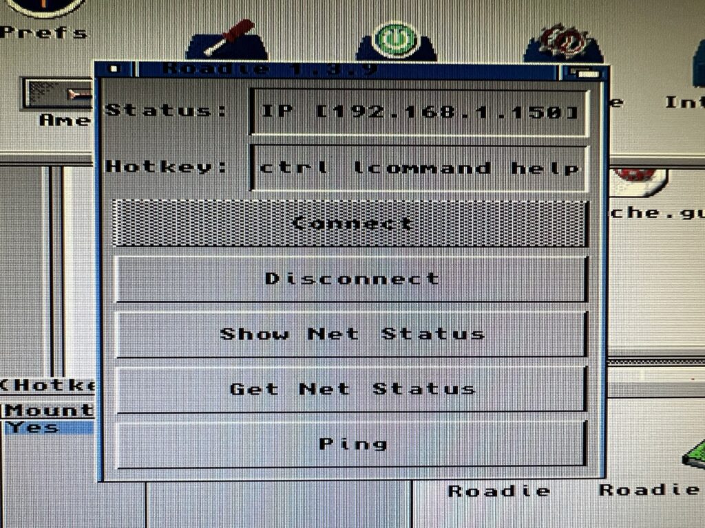
 

Using Roadie to find out my Amiga’s IP address.


After adding my Amiga as a trusted device I was able to ping my PC and connect to the share immediately.

If you too are experiencing firewall issues then hopefully my experience has given you enough pointers to sort them out for yourself. You might have to do some Googling but at least you should have an idea of what to search for!


Transfer Speeds & Conclusion

Transfer speeds are not as fast as the internal Compact Flash HD using the SCSI.device interface. I timed a few different file transfer operations to give some practical examples. A 3.5Mb LHA archive file copied from DH0: to DH1: took 6 seconds to transfer. It took the same time to transfer to my RAM Disk. That exact same file took 49 seconds to transfer to the SMB shared folder across the network. This is to be expected though – my A1200 is using a really old 10Base-T network card.
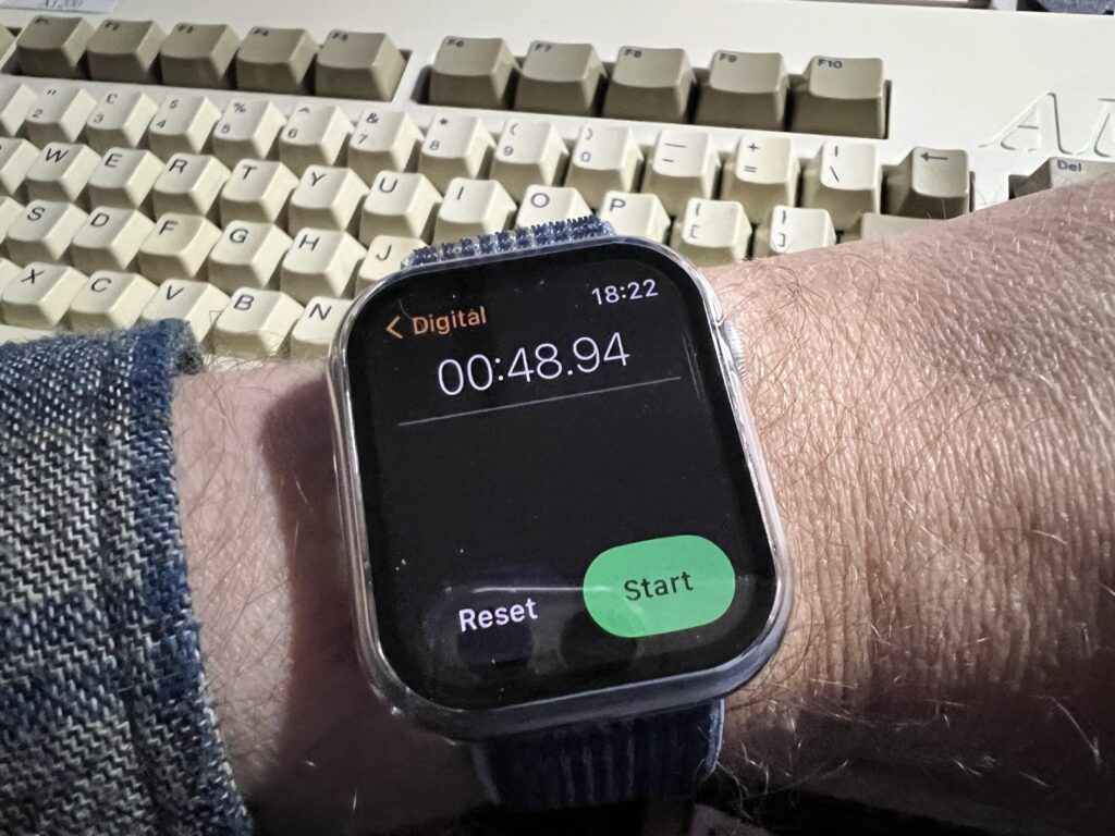
 

Guess who got an Apple Watch for Christmas and wanted an excuse to use it?


For the sake of completeness I timed transferring the same file to an SD card using my SDBox device. That took 26 seconds, so basically twice as fast as the SMB share. However that isn’t accessible to the PC when it’s in the Amiga and vice versa, plus there’s the faffing around swapping the card from one reader to another so probably slower all things considered.

In reality for most regular sized Amiga files you probably won’t notice much of a lag in moving them around at all. An ADF image takes 13 seconds to transfer which is perfectly acceptable in my view. Besides, these timings are missing the point really. The sheer convenience of having a drive that you can use to share files ‘on the fly’ between your PC(s) and Amiga(s) trumps any small time penalties experienced whilst doing so.

I have access to floppy disks, Zip disks, CDR’s, SD cards, PCMCIA CF cards but I choose to use the SMB Shared Folder most of the time when transferring stuff to and from my Amiga. It just works and its really convenient. That should speak volumes about the usefulness of such a setup so if you have the resources available, go for it!

Anyway I hope this article helps a few at least a few people access a network share on the Amiga. Let me know of your successes (or fails!) by leaving a reply below.
Amiga Tank Mouse Gets Laser Upgrade & Refurbishment

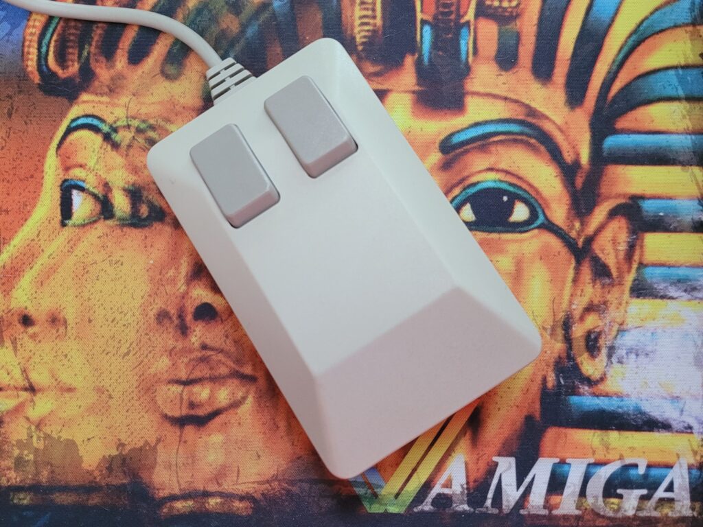
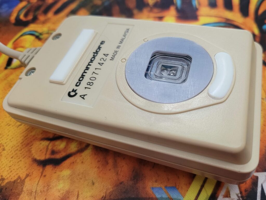
Love it or loathe it the Tank mouse is synonymous with the early Amiga computers and even though they’re very angular in design I actually find the ergonomics of them quite comfortable to use. However what I no longer appreciate is the imprecise and clunky ball mechanism and the constant need to remove the fluff and detritus that always collects on the rollers.

Now I know that some may consider this part of the nostalgia, and if it was only used occasionally then I might possibly agree, but as someone who uses my old machines on a regular basis I say balls to that – give me an optical mouse any day! With this Amiga Laser Mouse Upgrade kit I picked up from AmigaStore.eu I can finally have the best of both worlds!


Amiga Laser Mouse Upgrade

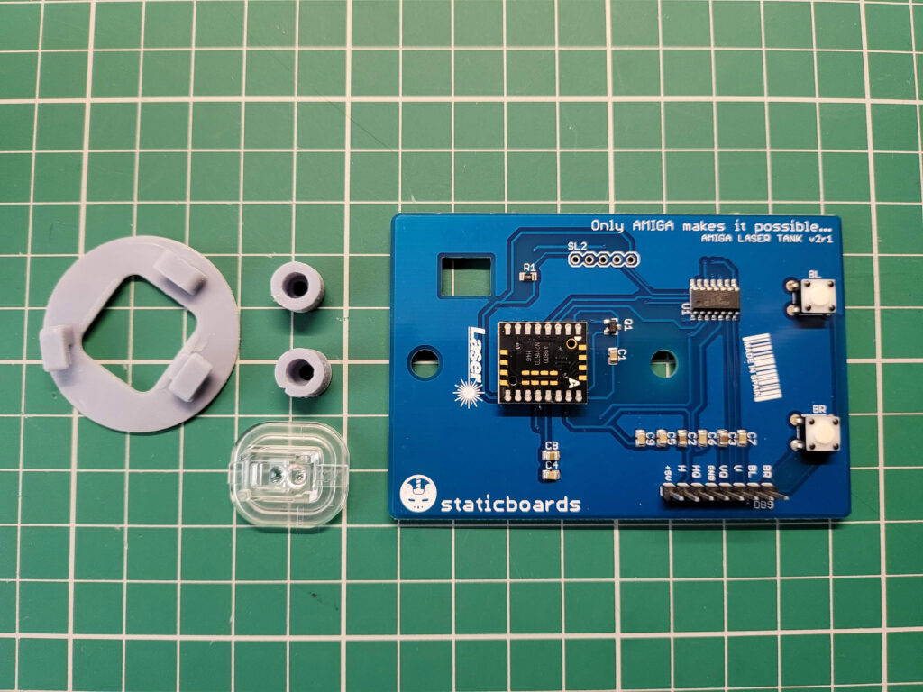
The laser upgrade kit contents.


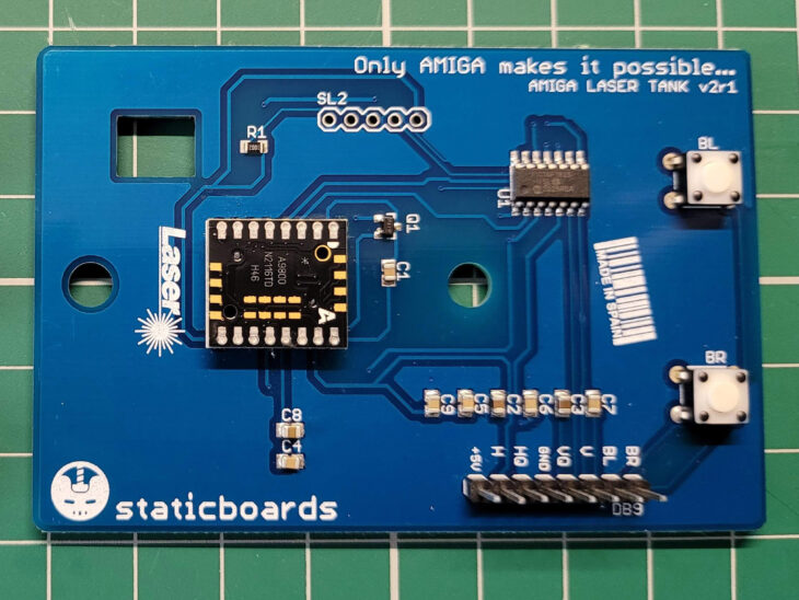
The upgrade kit took around a week to arrive and included a single PCB with optical sensor, a little lens to fit over it, a replacement cover and a couple of little plastic spacers. There was also a small instruction booklet.


Amiga Laser Mouse Upgrade

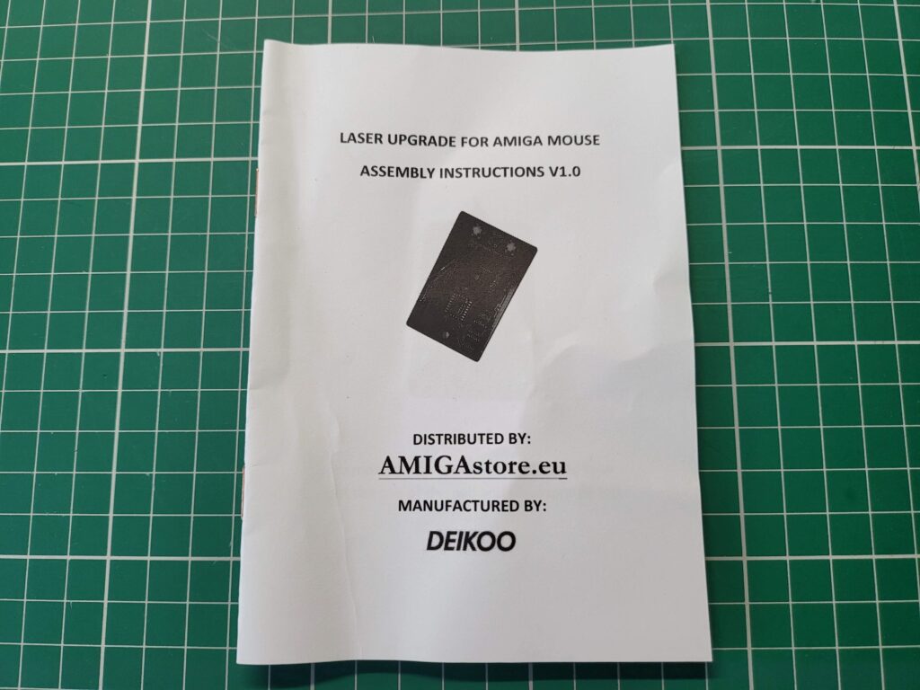
Instruction manual.


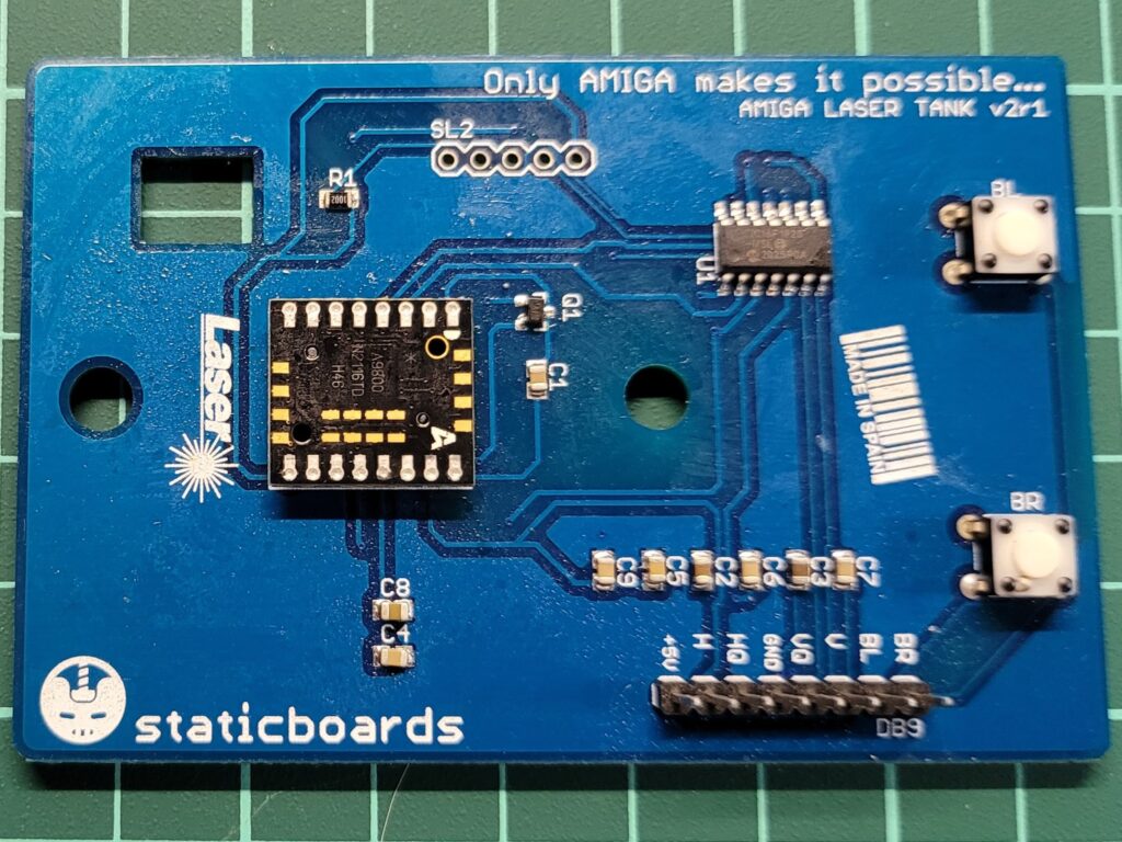
Annoyingly everything (even all the plastic parts) was covered in sticky soldering flux. All the components came supplied in a small Ziplock bag so the flux must have smeared itself onto everything in transit. I had to spend a good fifteen minutes giving everything a thorough cleaning with Isopropyl alcohol to get rid of the residue.


Amiga Laser Mouse Upgrade

What the board looked like before the excess flux was cleaned off it.


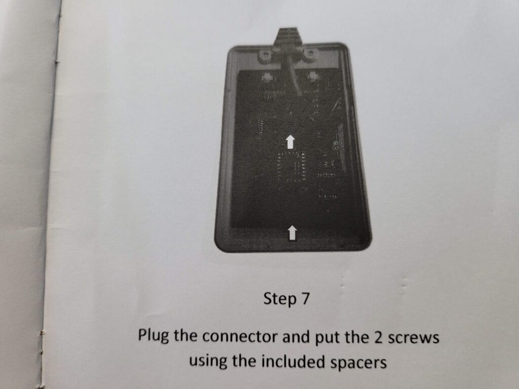
The manual was also a little disappointing – all the photos were dark and murky so details were near impossible to see. It was like a photocopy of a photocopy of a… well you get the idea. Thankfully it’s a pretty straightforward install and you don’t really need much guidance but it’s definitely something that could do with addressing in the future.


Amiga Laser Mouse Upgrade

Quality of the photos in the manual leave a bit to be desired.


Preparations

My tank mouse had been sat in a cupboard, unloved, for many years so when I dug it out for this project it was looking a little sorry for itself and was quite yellowed, especially underneath.


Amiga Tank Mouse

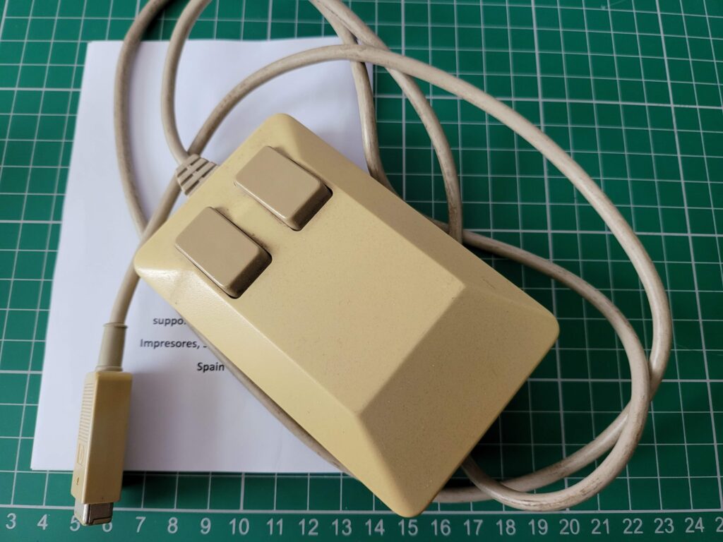
Top of the mouse doesn’t look too bad, a little dirty perhaps but nothing major.


One of the glide pads on the base of the mouse was also looking quite tatty so I wanted to sort this out too.


Amiga Tank Mouse

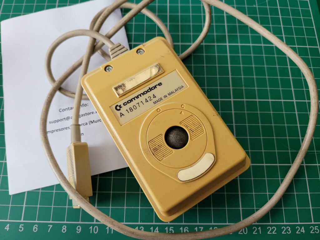
The underside of the mouse is a completely different story. It’s turned a very unpleasant looking shade of ‘nicotine’ yellow.


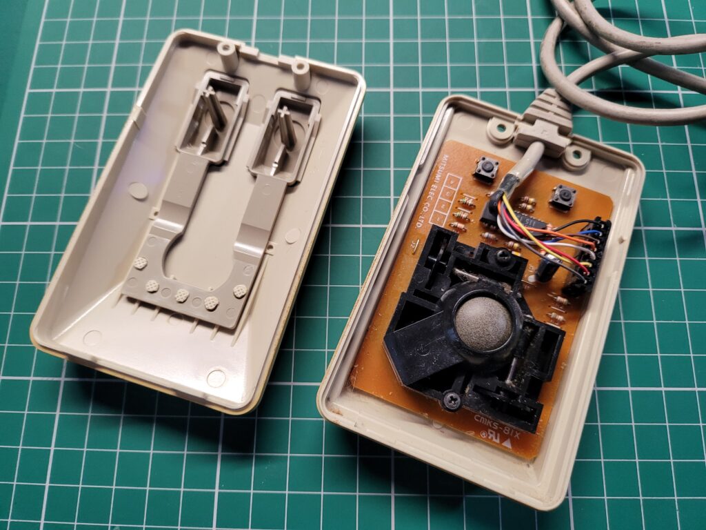
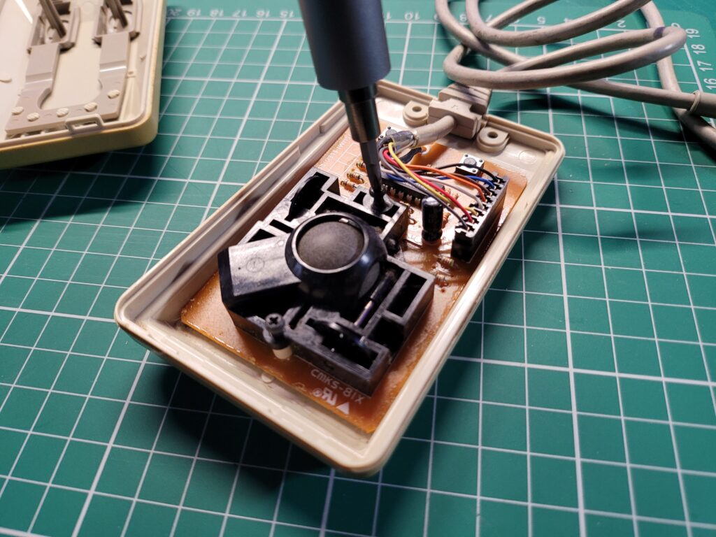
Dismantling the mouse was pretty straightforward. Two small silver screws either side of the cable entry point needed removing to free one end of the case, whilst a couple of plastic clips secured the opposite end and just needing to be gently teased apart.


Amiga Tank Mouse Internals

With the case opened you can see the ball mechanism in all its fluffy glory.


There were a further two black screws above and below the ball mechanism, holding the circuit board in place that also needed removing. I set both sets of screws aside somewhere safe as they would be needed later on when putting it all back together.


Amiga Tank Mouse Ball

The two black screws at the top and bottom of the black plastic ball housing need to be removed and put to one side safely for later.


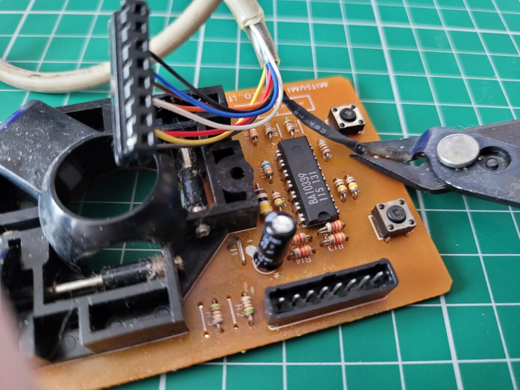
Once the board was out, the cable connector was removed and the ground wire soldered to the circuit board cut. It isn’t required for the the new laser board to work.


Amiga Tank Mouse Circuit Board

The black ground wire that is soldered directly to the board needs to be cut here.


The old board is surplus to requirement now but I’ll be keeping hold of it as it may come in handy to repair another tank mouse in the future.


Amiga Tank Mouse Bottom

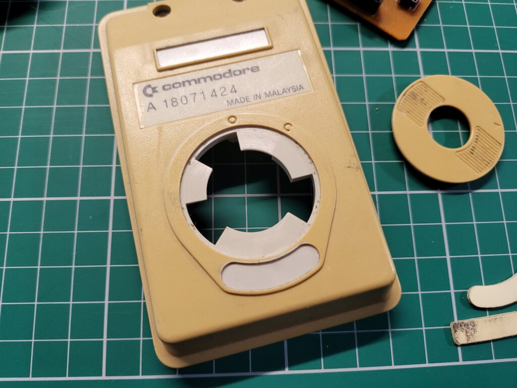
The extent of the yellowing was clear to see once the cover and sticky pads had been removed.


After removing the old glide pads and the cover off the ball compartment the extent of the yellowing was pretty evident. The original beige colour could clearly be seen underneath. Hopefully this is the colour the whole mouse will be by the end of this project after a spot of Retrobrighting.


Retrobriting

I live in North West England so hot sunny weather is something of a rarity here so I had no chance of just using the suns UV to do the job as I have in the past. Just as an example, at the time of writing it’s raining and about 12’C outside.

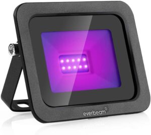
To this end I decided to buy the necessary kit off Amazon so I could do this sort of thing indoors whenever I wanted in future and not be beholden to the weather. I picked up a small 10W UV lamp that came with a built-in bracket and power cable with inline on/off switch and moulded UK plug.


The UV lamp.


I also got a 500ml bottle of 6% Hydrogen Peroxide to make a nice bath for the mouse to soak in. I only had to use half of it too so could have got away with buying a smaller bottle.


Hydrogen Peroxide.


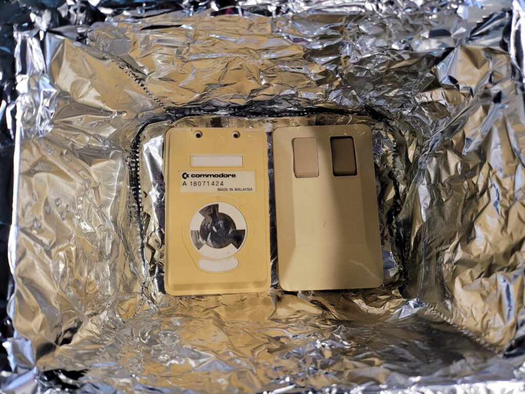
To begin the process I first gave the mouse case a clean in some soapy water before putting both sides into a tin foil lined plastic box.  The idea behind the tin foil was two-fold. Firstly it would reflect the UV light around the box helping ensure even coverage and secondly it would prevent the UV light from making the plastic box brittle and possibly even bleaching the colour out of my desk.


Retrobrighting

Plastic mouse case sitting in the bottom of a tin-foil lined box.


I then covered them with a 50/50 mix of warm water and Hydrogen Peroxide solution. I chose a box that wasn’t much bigger than the mouse case which kept the amount of fluid needed to a minimum.


Retrobrighting

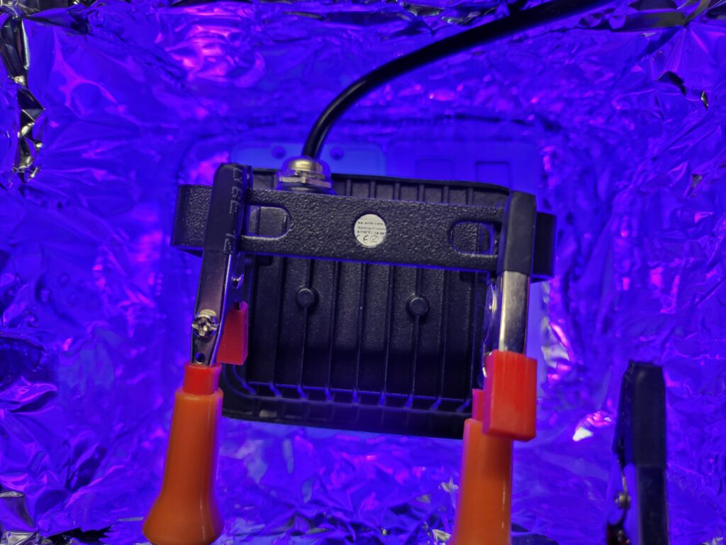
UV light suspended over the box.


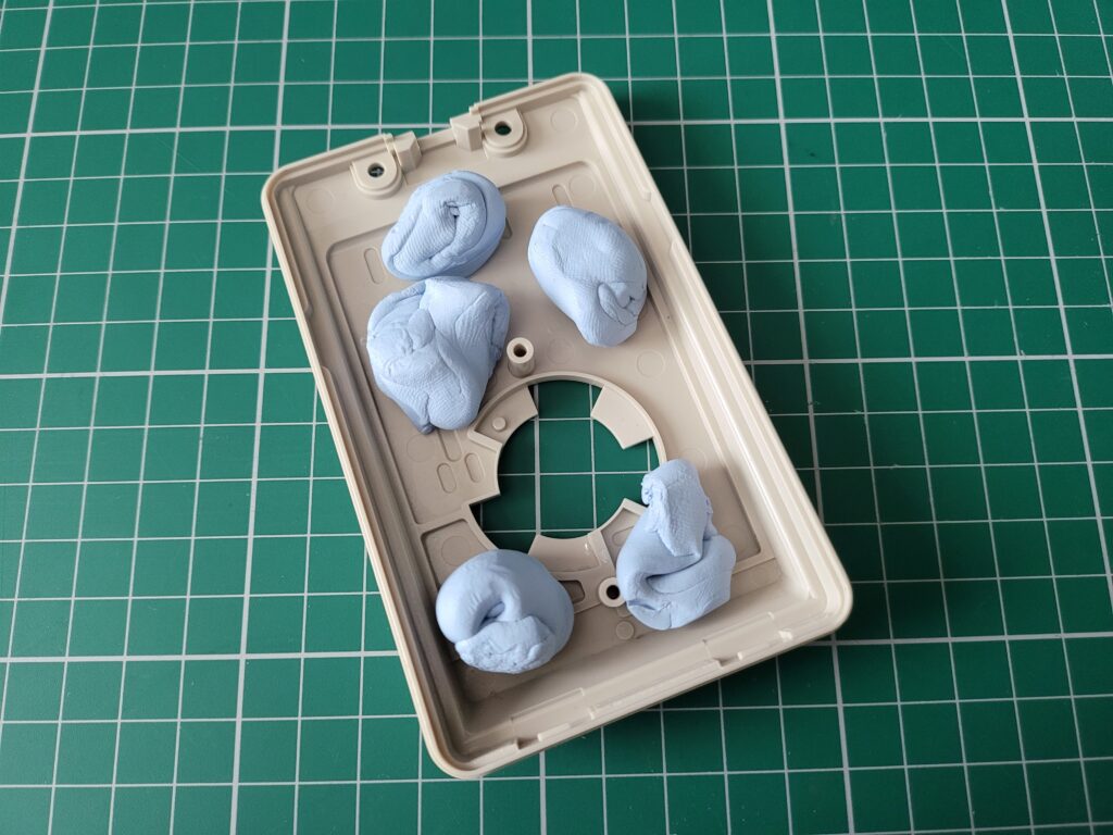
Once the case halves were immersed in fluid I positioned the UV light over the top of the box and held it in place with some helping hands and switched it on. Everything looked good so I left it for about an hour and then came back to check on it. The plastic parts were covered in hundreds of tiny air bubbles which meant the process was obviously working. The bad news was that those same bubbles were causing the case to float up and no longer be covered in the hydrogen peroxide solution. Over a period of a few hours I had to keep adding blobs of blu-tack to the underside of each part before they would finally stay submerged.


Retrobrighting

Blu-tack weights to keep the case submerged.


Once I was happy that the case wouldn’t float up any more and that the UV light wasn’t going to overheat or nose-dive into the liquid I shut the door to the man cave and left it all overnight to marinate.


Results

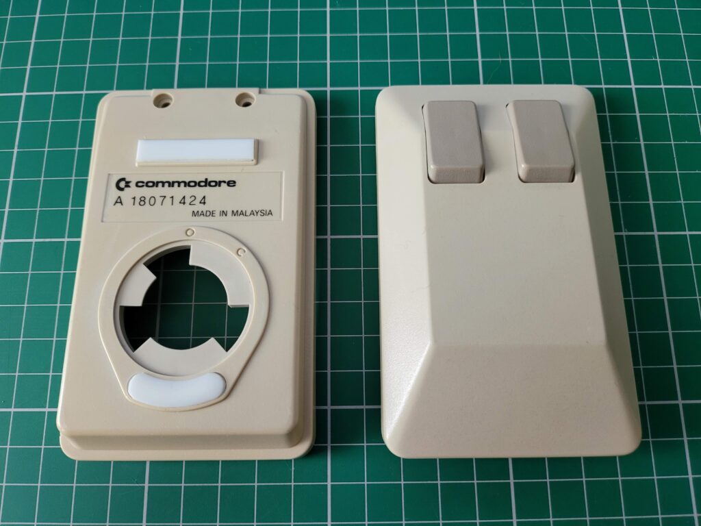
The following evening after work I fished the case out of the water and had a look at the results which you can see in the photo below. Needless to say I was pretty chuffed with how it turned out as everything was now a nice uniform beige colour top and bottom.
 

Retrobrighting Results

Freshly retrobrighted cases.


Compared to the mouse ball cover (which I deliberately didn’t treat – see photo below) the difference was night and day. All in I’d say the case probably spent about 24 hours under the UV lamp in the hydrogen peroxide solution. Perhaps they might have been ready a bit sooner but I wasn’t able to keep checking in on them. Either way I’m quite happy to wait a day for such a good result. Incidentally, the liquid solution was at room temperature (about 22′-24’C) the whole time, I didn’t use any kind of water heater.


Retrobrighting Comparison

Spot the difference.


Replacing the Glide Pads

Unfortunately in my excitement to finish my mouse refurb I forgot to take pictures of the case before fitting the new glide pads so you’ve already seen pictures of them fitted.

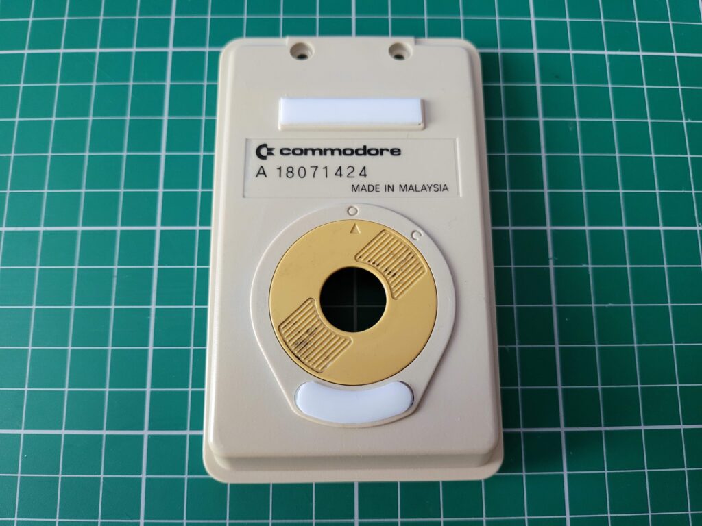
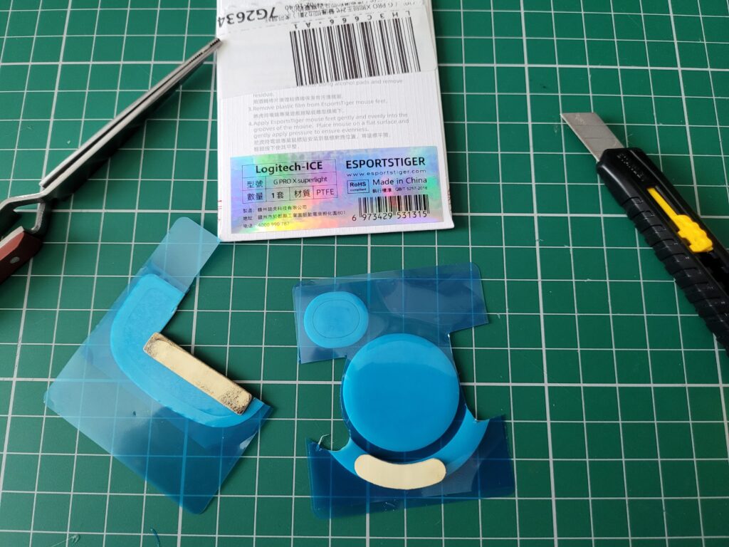
To get the correct sizing for the glide pads I simply placed the old pads on top of the new ones (photo below) and cut around the outline with a sharp craft knife. I struck it lucky with the curved pad at the bottom as it matched the curvature of the new one exactly so I only had to cut the rounded ends. The only slight issue I had was that the new pads were half the thickness of the old ones so I needed to cut out two of each and stick them on top of each other. If I hadn’t done this then they would not have cleared the recesses in the case and they’d have been a waste of time.

Anyway, I’m really happy with the end result as the mouse glides around like a dream now. I also still have enough material left to kit out another mouse should the need ever arise.


Mouse glide pads

Cutting out the glide pads.


Incidentally the mouse glide pads I bought were designed to fit a “Logitech G Pro X Superlight”. There are plenty available on eBay at the time of writing.


Installing the Amiga Laser Mouse Upgrade Board

With the case now looking fine and dandy it was time to fit the laser upgrade itself. The first task was to fit the new plastic cover in place of the original. This is made out of some sort of flexible plastic material (TPU?) and I found it didn’t want to sit completely flat. Luckily it doesn’t hinder the use of the mouse but I might add a few tiny blobs of glue around the edge to hold it securely if it proves to be an issue in the future. Not sure why they made it grey either – definitely loses some style points for not being beige! At some point in the future I might have a go at 3D printing a better looking cover for it.


Amiga Laser Mouse Upgrade

New mouse cover fitted – it now has a square hole to better fit the new laser mechanism.


The next task was to fit the transparent plastic ‘lens’ to the circuit board. This slots into the bottom of the board and thanks to the different sized plastic pins it has on the corners it would only fit one way.


Amiga Laser Mouse Upgrade

Plastic lens fitted to the underside of the circuit board.


With the lens fitted I carefully lowered the board into the bottom of the mouse case. The plastic lens needed to be held in place during this operation otherwise it kept falling out. Once the board was is in place, the flexible plastic cover fitted earlier prevented it from falling out through the bottom.

.

Amiga Laser Mouse Upgrade

New board fitted into mouse base.


Next the two little plastic spacers were fitted over the existing screw posts allowing the board to be secured in place using the original black screws removed earlier. I then reattached the cable connector to the pin header on the new board.


Amiga Laser Mouse Upgrade

Board secured in place and cable reconnected.


Now I just needed to replace the top half of the case by carefully relocating the clips at one end and securing the other with the two silver screws.


Amiga Laser Mouse Upgrade

Job done.


Test Drive

The only thing left to do now was plug it into my Amiga and take it for spin. Happily it performed very well indeed,  it was just like using a brand new mouse – which is effectively what it is now. I did find the mouse buttons to be quite stiff compared to modern mice but it’s something I could get used to. The stiffness will be down to the type of switches they’ve used in the construction of the new board and they may possibly soften up a bit in the fullness of time too.


Amiga Tank Mouse

Mouse back in action!


All in all I can heartily recommend this laser upgrade kit. Sure, the photos in the instruction manual are a bit ropy and the grey mouse cover isn’t perfect but the stuff that really matters, the laser mechanism itself, is spot on. This upgrade has totally transformed my crusty old tank mouse into a device worthy of being used in the 21st century.

Unfortunately at the time of publishing this if you want one you will need to register your interest on their website as they are currently out of stock. Still, good things come to those that wait!


Amiga Laser Mouse Upgrade

Close-up of the underside of the mouse.


The A500 Mini Review

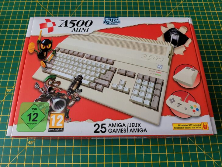
Despite the fact that I already own a real A500 an A1200 and a CD32 I still pre-ordered ‘The A500 Mini’ as soon as they were announced, such is my love for these old Commodore machines. I also picked up both ‘The C64 Mini’ and Maxi despite owning a VIC20 and C64 which they both emulate. I suppose even if I never use them much they’re still really cool devices to own and display but the truth is I just can’t resist these (or any) sort of gadgets.

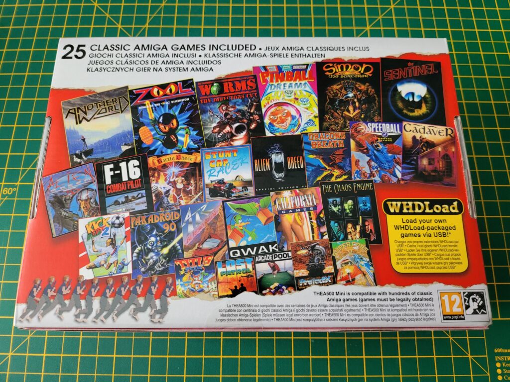
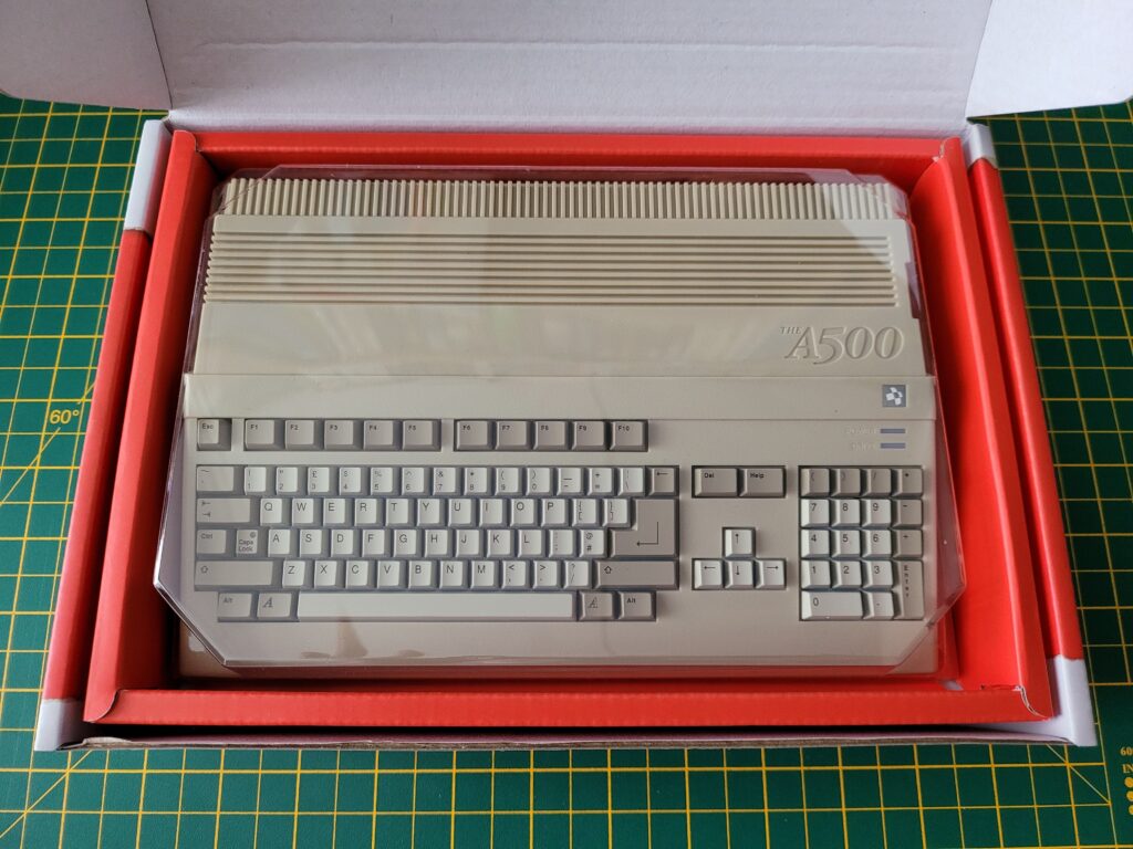
First impressions were terrific. The A500 Mini came in a very attractive and colourful box adorned with pictures of the computer and peripherals on the front and a gallery of the included games on the back. The box was surprisingly heavy too, something I definitely wasn’t expecting.


The A500 Mini

Back of The A500 Mini Box.


The A500 Mini comes with the following 25 games pre-loaded:

Alien Breed 3D
Alien Breed: Special Edition’92
Another World
Arcade Pool
ATR: All Terrain Racing
Battle Chess
Cadaver
California Games
The Chaos Engine
Dragons Breath
F-16 Combat Pilot
Kick Off 2
The Lost Patrol
Paradroid 90
Pinball Dreams
Project-X: Special Edition 93
Qwak
The Sentinel
Simon the Sorcerer
Speedball 2: Brutal Deluxe
Stunt Car Racer
Super Cars II
Titus The Fox: To Marrakech And Back
Worms: The Director’s Cut
Zool: Ninja Of The “Nth” Dimension


What’s in the Box?

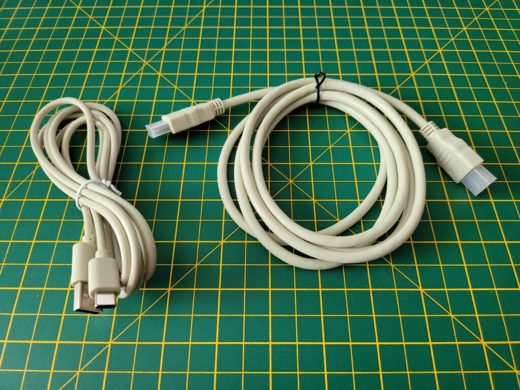
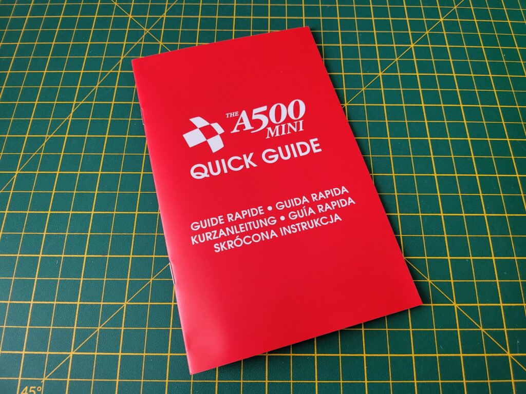
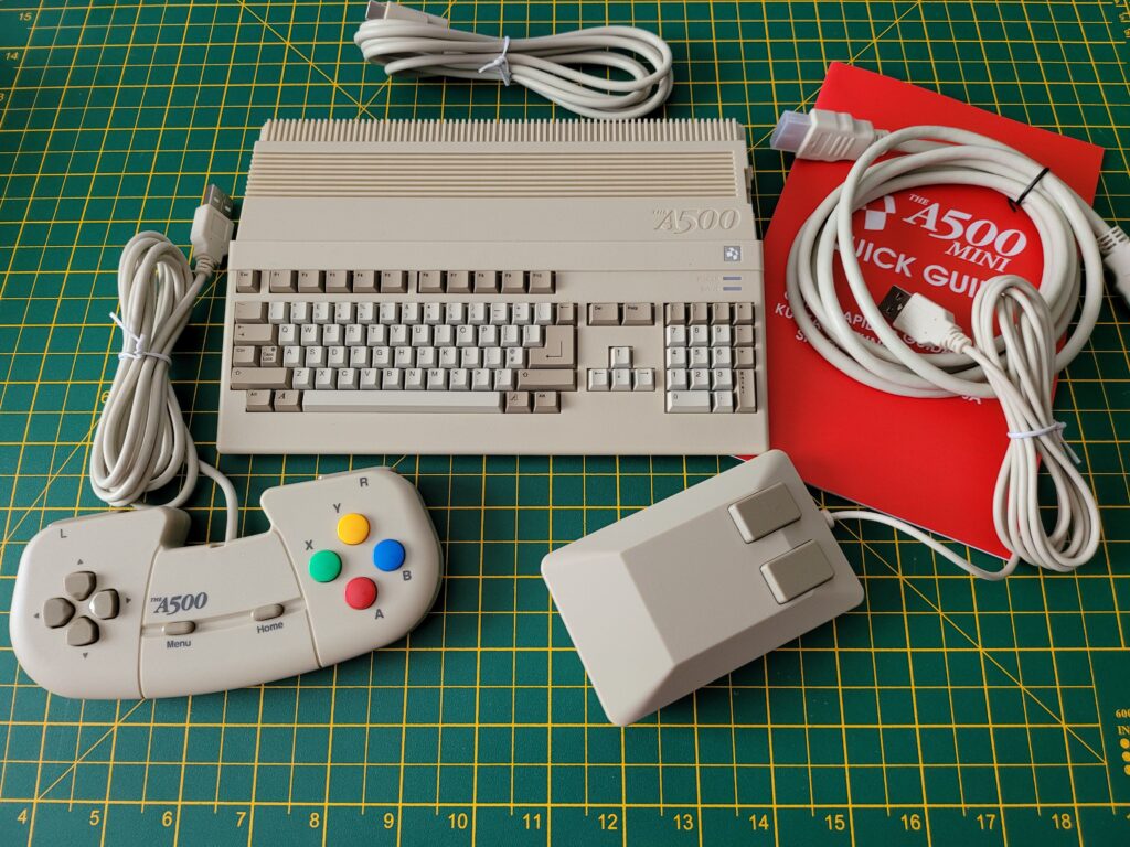
Opening up the box revealed the A500 mini itself, an optical USB Tank mouse, CD32-esque USB controller, quick start guide, HDMI cable and a USB C power cable.


The A500 Mini

The A500 Mini (with plastic cover).


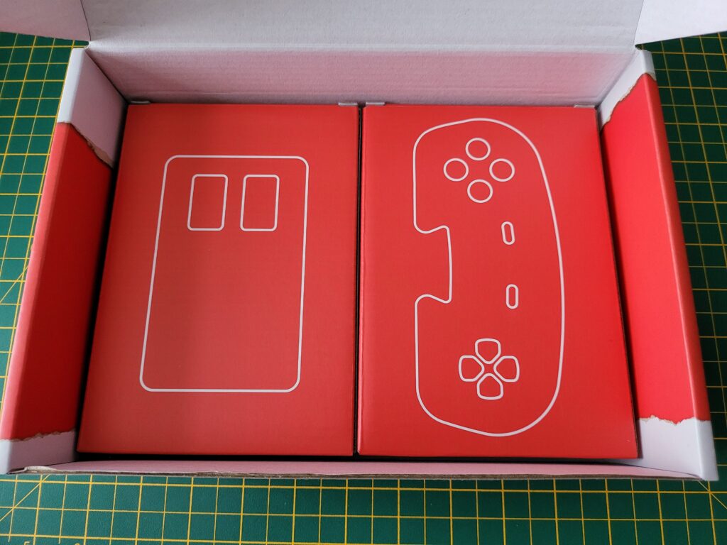
The mouse and controller were tucked away under the A500 Mini inside their own little boxes.


The A500 Mini

Controller and Mouse Boxes.


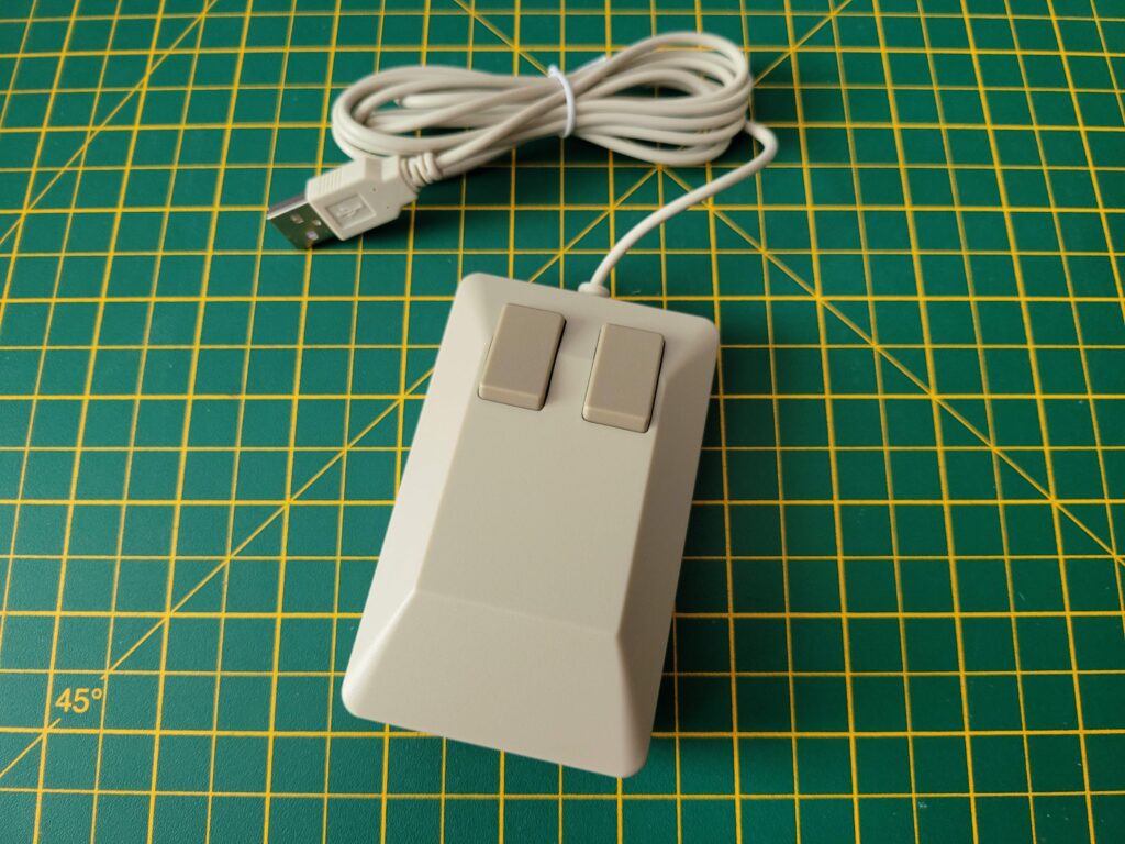
The tank mouse is a perfect, slightly smaller replica of a real Amiga tank mouse.


Tank Mouse

The A500 Mini Tank Mouse.


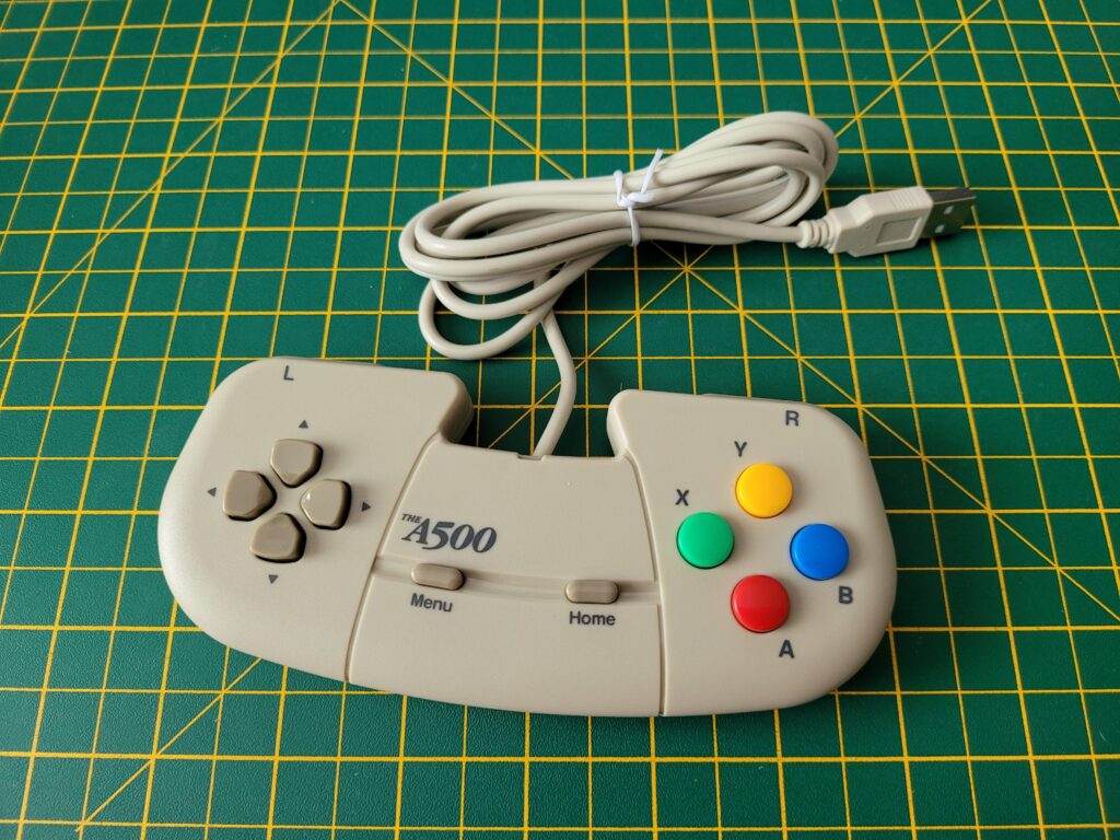
The design of the gamepad was clearly inspired by the CD32’s controllers.


The A500 Mini

The A500 Mini Controller.


A suitably beige USB C power cable and HDMI cable are also included. I have to admit it was nice to see the adoption of USB C for the power as most of my modern day kit uses this standard now. You have to provide your own USB power socket but that was to be expected – most of us have plenty of these lying around.


Cables

USB C Power and HDMI Cables.


The Quick guide is literally just that. Strip away all the pages devoted to other languages, health and safety gubbins and a list of the package contents and you are left with a meagre 2 pages of instructions. The full 48 page English instruction manual is provided online – here’s the URL given in the quick guide. For a retro product I did find this disappointing and would much rather have had all of this info in a nice spiral bound or hardback manual. Hopefully they release this as an optional extra shortly like they did with the ‘The C64 User Manual‘.


The A500 Mini Guide

The A500 Mini Quick Guide.


A Closer Look at the A500 Mini

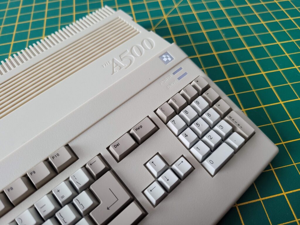
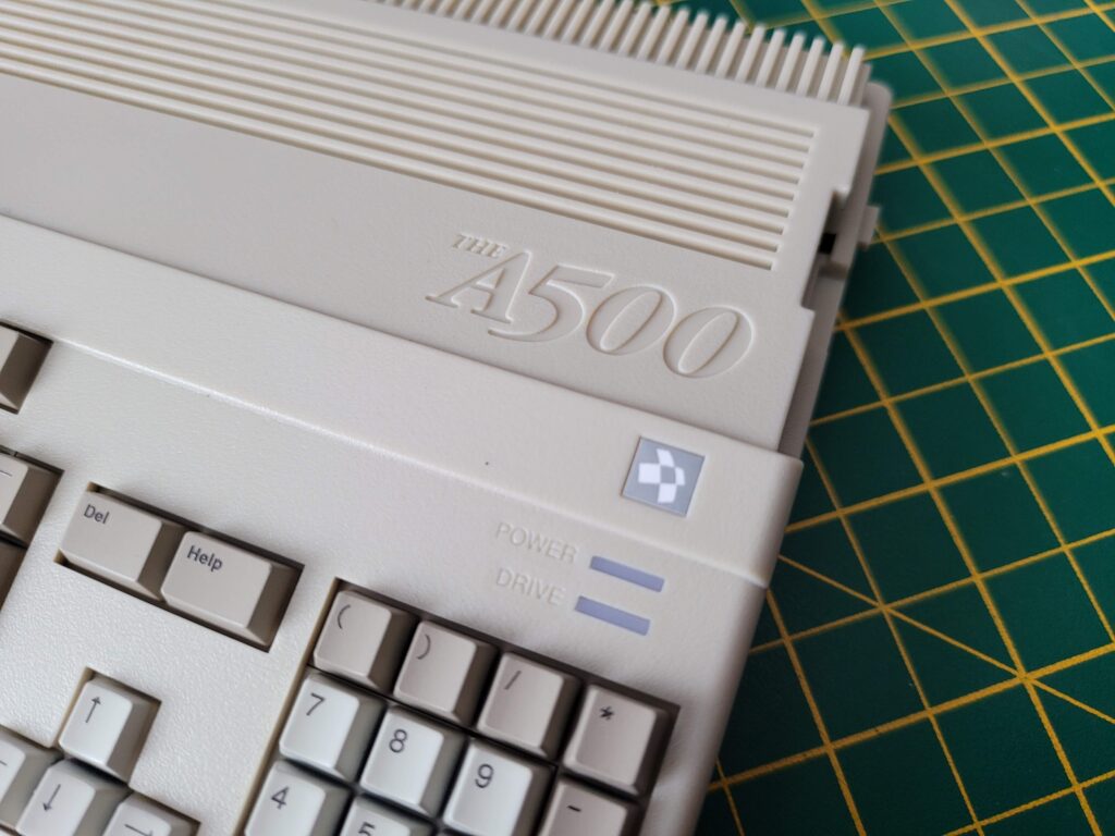
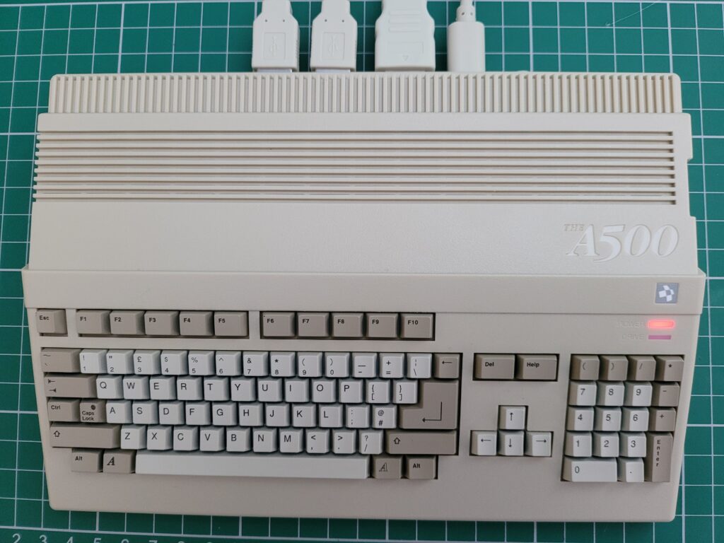
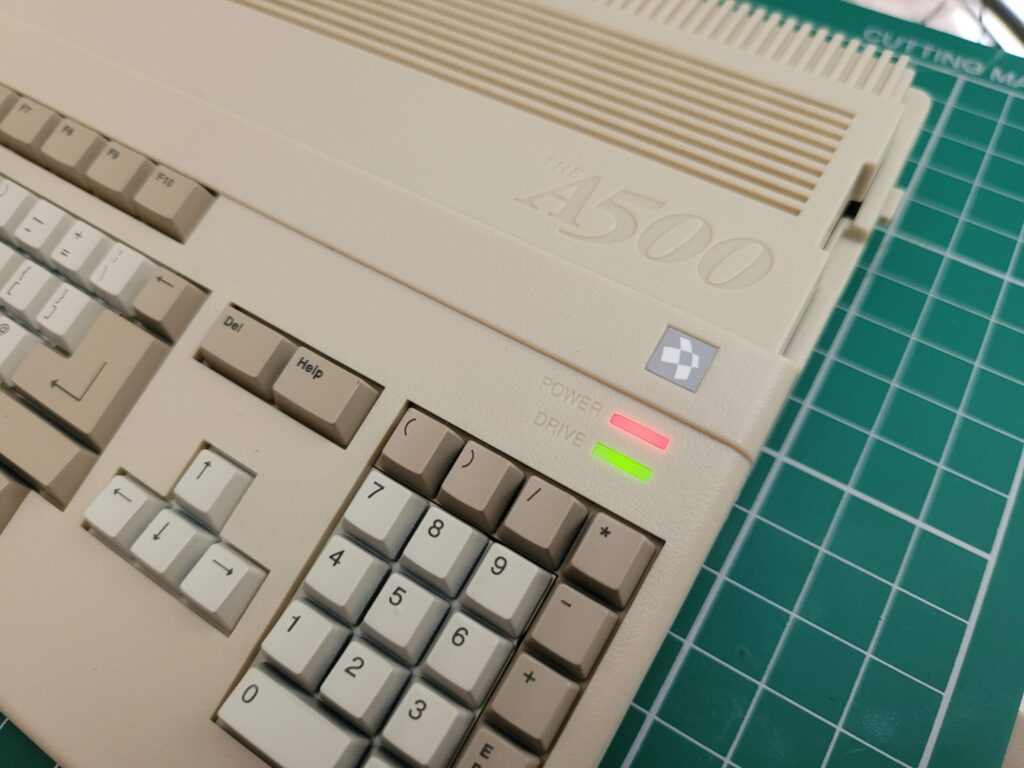
From the photos you could certainly be forgiven for mistaking the A500 Mini for a real A500 especially if you last used one in the 80’s or 90’s. Obviously it doesn’t have the Commodore logo on display but it’s only really when you see the USB ports on the back that you realise something isn’t quite right.

If you try to press any of the keys you will quickly realise something else isn’t right too. Just like with The C64 Mini the keyboard is completely non-functional and just for show. It’s certainly very convincing visually though with each key perfectly formed!


This slideshow requires JavaScript.


The attention to detail on the case is amazing and really makes me wonder why I’ve been waiting for four years now for my ‘Compatible A500 case’ to be made!


The A500 Mini

Spot the subtle differences from a real A500.


The case displays the wording ‘The A500’ rather than Amiga and their own logo rather than the familiar Commodore ‘Chicken head’ which is obviously for copyright reasons.


The A500 Mini

Those keys look so real!


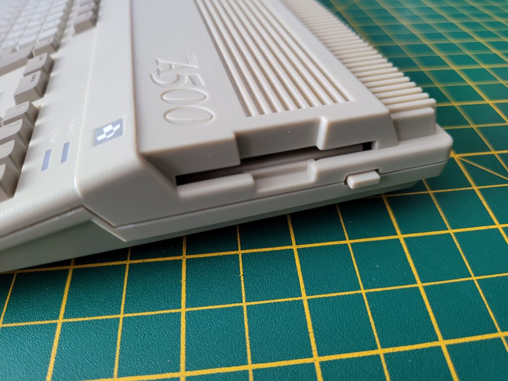
The floppy drive and eject button are very convincing but totally non-functional. Its a real shame they didn’t incorporate an SD card slot for expanding your game library here. At the very least they should have put an extra USB port here so we could insert our USB stick like it was a floppy disk…


The A500 Mini

Close-up of the non-functioning ‘floppy disk drive’.


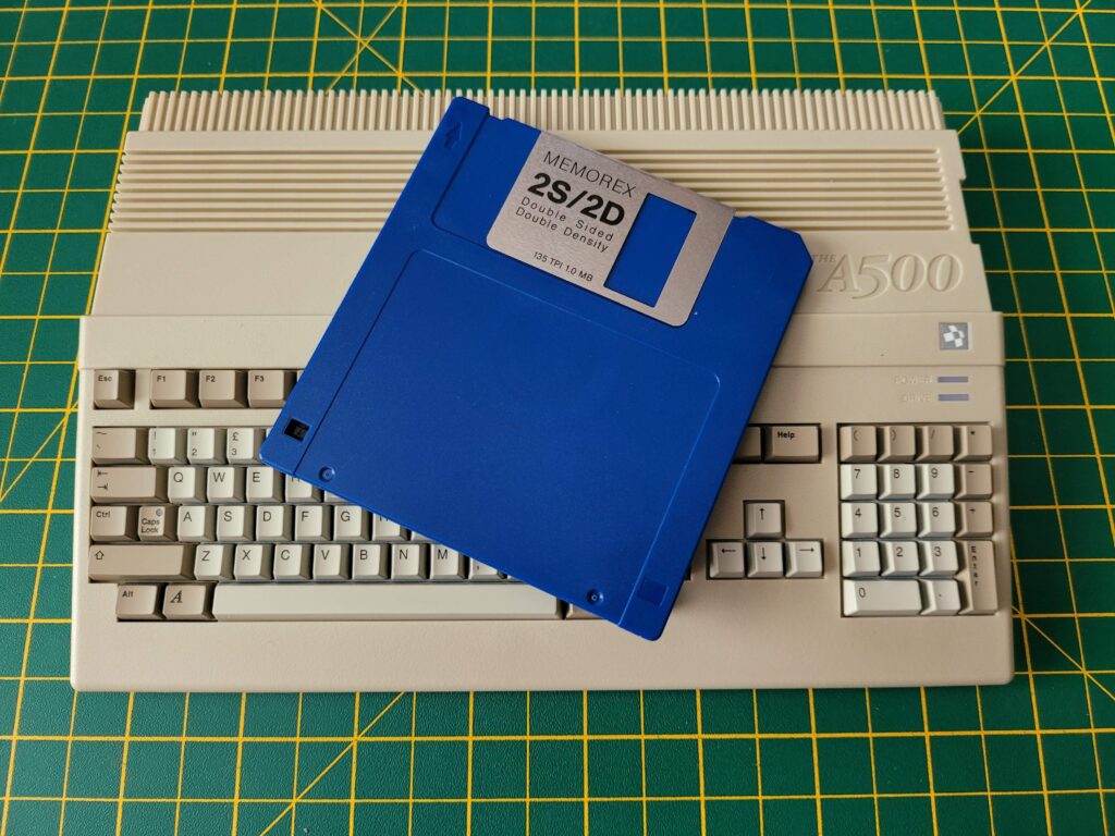
The diminutive scale of The A500 Mini becomes instantly apparent when compared to a 3.5″ floppy disk!


The A500 Mini

A500 Mini Compared to 3.5″ Floppy Disk.


Ports

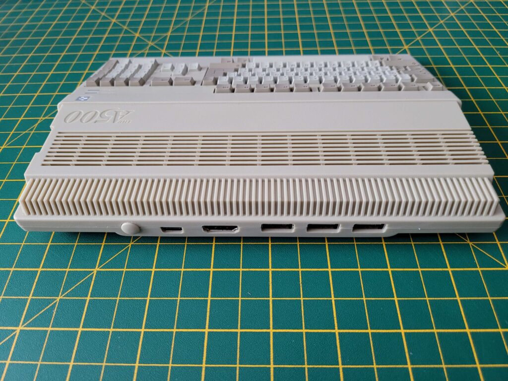
Unlike the original A500 the The A500 Mini come with a very modest selection of ports comprising USB-C for power, a full-size HDMI for video and 3 USB ports for the mouse, controller and memory stick with extra games on. There’s also a power switch included on the back.

I really think there should have been an extra USB port included here for attaching a USB keyboard. If all you are interested in is arcade style games then you’ll be fine. However if simulation games are more your thing (like the Microprose games that needed keyboard overlays) then you are going to need a USB hub to add a keyboard which is going to make for a very messy setup indeed.


The A500 Mini

Connectivity: From left to right, Power button, USB-C power socket, HDMI Video, 3x USB ports.


Here’s a photo of everything you get inside the box. The relative size of the A500 Mini becomes apparent when it is sat next to the mouse and gamepad.


The A500 Mini

Contents of the box.


What’s it like to use?

After plugging all the cables in and pressing the on/off switch the power LED came to life. Surprisingly the drive activity light doesn’t actually operate when loading the UI or any of the included games.


The A500 Mini

All plugged in and ready to go!


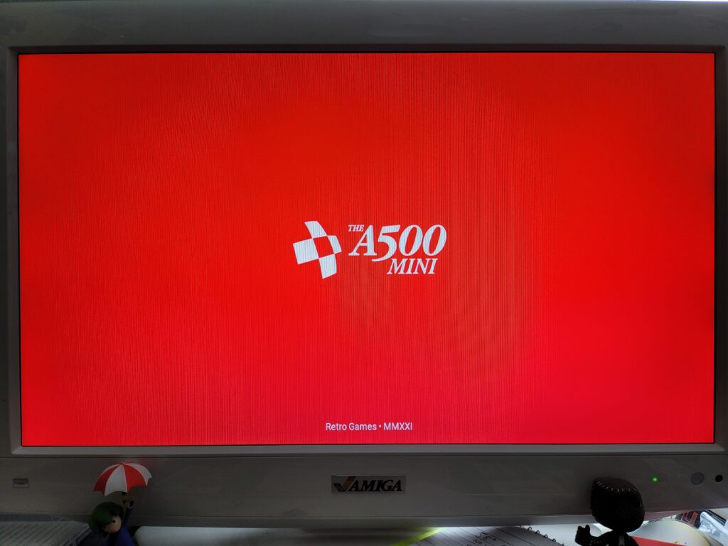
After approximately 8 seconds of staring at a blank TV whilst it booted up a very snazzy red and white A500 Mini splash screen appeared.


The A500 Mini

The A500 Mini Boot Screen.


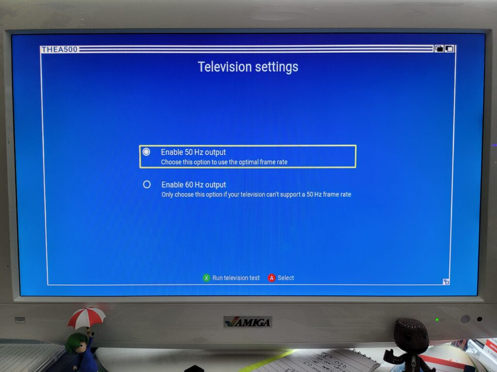
As this was the first time the device had been used a couple of configuration screens popped up allowing me to choose my language and also whether I wanted to use 50Hz or 60Hz.


The A500 Mini

TV Settings Screen.


Naturally being in the UK I chose the superior 50Hz option for the optimal frame rate. 🙂


The A500 Mini

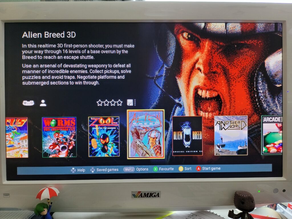
The A500 Mini User Interface.


After a quick test to make sure the mode was compatible I was presented with a gorgeous user-interface (UI). The UI features a scrolling carousel of Amiga game box art along with changing graphic montages from each game in the background. Some very relaxing ambient synth music plays softly whilst you navigate the UI too.

There are icons showing whether each game utilises the controller and/or mouse and how many players it supports. Each game can have a user star rating too, from 1 to four stars. As the carousel allows you to change the sort order between Author, Genre, Year, Publisher and Favourite this affords you the option of having the games displayed by order of preference should you want it.


The A500 Mini

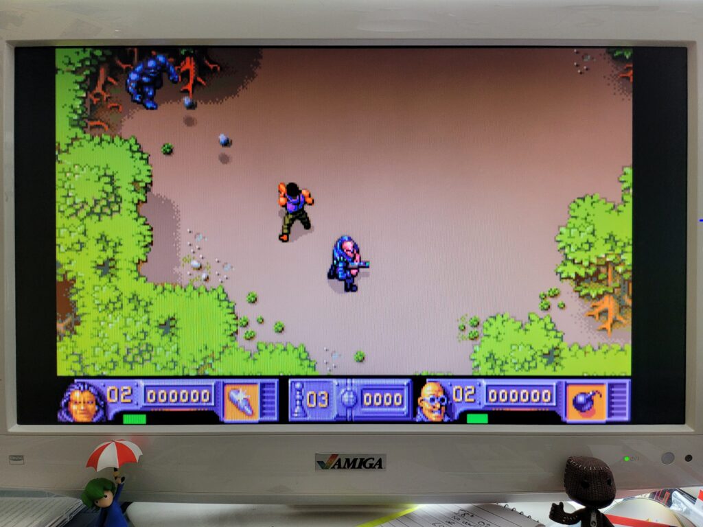
The Chaos Engine playing as good as ever.


Over the course of an afternoon I had a lot of fun trying out all of the pre-installed games on The A500 Mini and they all ran perfectly. I didn’t do any side by side comparisons but nothing gave me pause for concern and I was very impressed with just how slick everything was. Games loaded in seconds – there’s no simulated loading times here.

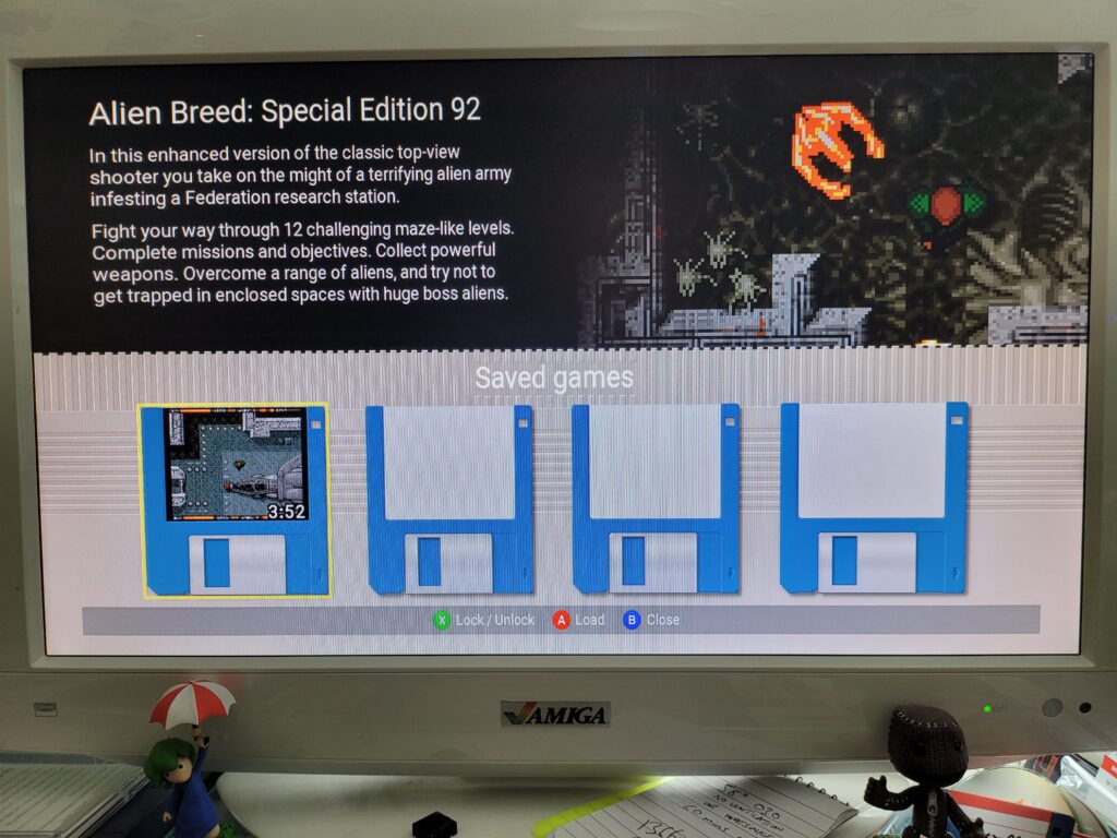
There are plenty of quality of life features too. For example each game supports up to 4 ‘save states’ allowing you to instantly save your progress at any point in any game. It even includes a ‘disk label’ incorporating a screen capture of exactly what you were doing at the moment you created the save state to help you recognise it in future! I think these are a great feature and who knows – in 30 years time someone might be using using a PS5 mini console and using save-states to brute force through a boss encounter in Elden Ring…


The A500 Mini

Alien Breed Save State with thumbnail ‘disk label’.


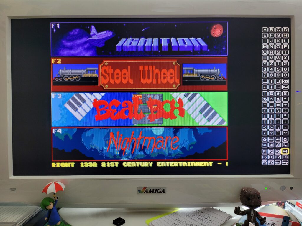
Some of the included games need rudimentary keyboard support in order to work. Pinball Dreams is a good example, requiring the use of the function keys to select which level you want to play. The handy virtual keyboard (invoked by tapping the menu button) worked like a charm here. However for games that require frequent keyboard inputs or text adventures like The Pawn you would definitely need to use a USB keyboard.


The A500 Mini

Selecting a level in Pinball Dreams using the virtual keyboard.


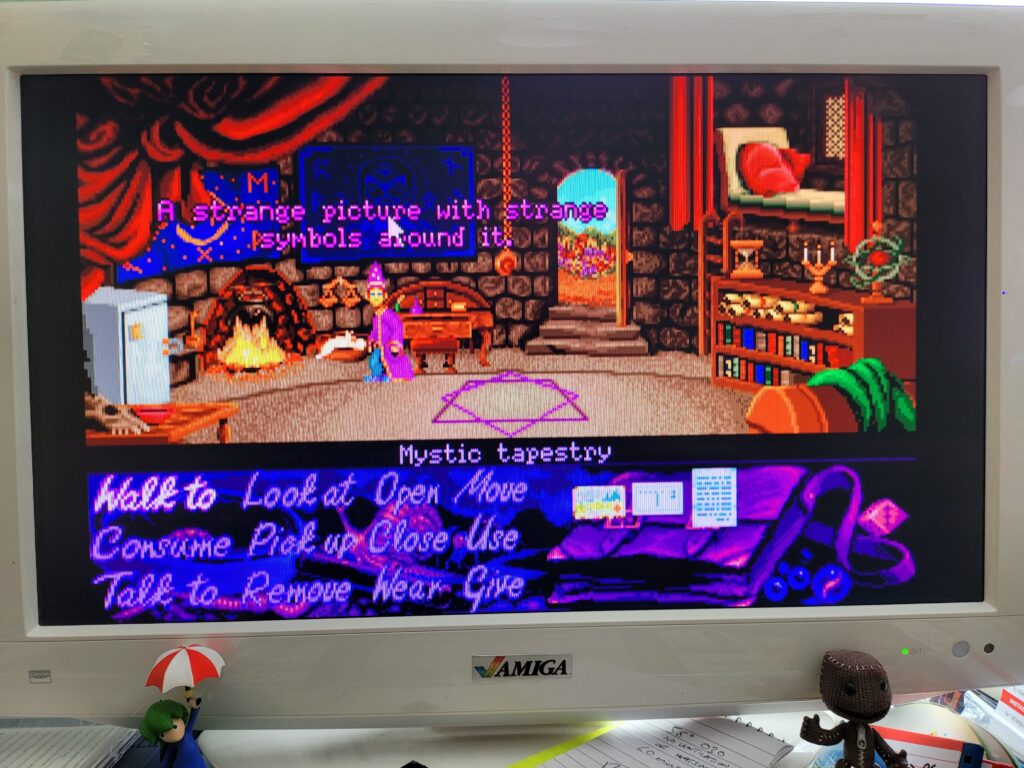
Happily the tank mouse is a pleasure to use in the games that support it, in Simon the Sorcerer for example. I should point out that the main UI doesn’t support it at all though – you must use the controller to navigate around that.

Unlike the original A500 mouse this new one incorporates a modern optical sensor under the hood and is all the better for it. I’m not really nostalgic about the old ball mice – they were a pain and required constant cleaning. Even when new they were not as accurate in use as a cheap optical mouse is now. I’ve been using optical mice with all my Amiga machines for years which should speak volumes.


Simon the Sorcerer

Using the mouse in Simon the Sorcerer.


Tweaking the settings

So the included games all work like a charm – but there’s still room for improvement. There’s a bunch of options you can mess around with to alter each game to your personal preference. The settings screens all feature a Workbench 1.3 Window effect which is a nice nod to the past and another example of the thought that has gone into this product.


The A500 Mini

Display Options.


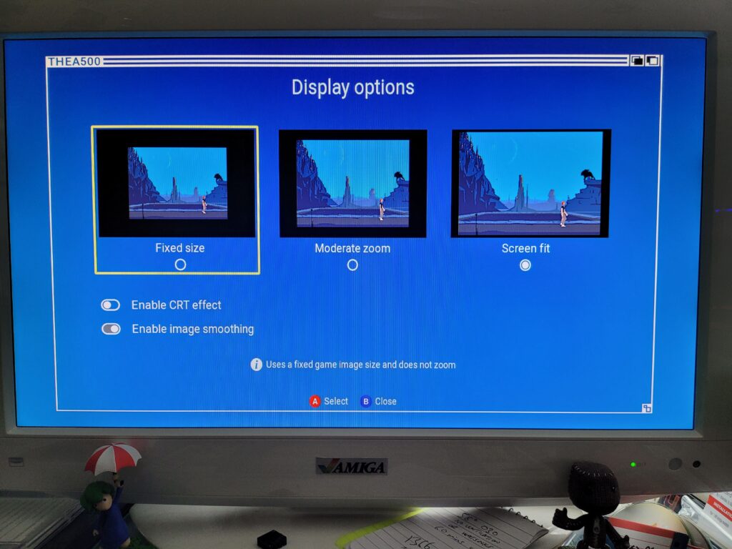
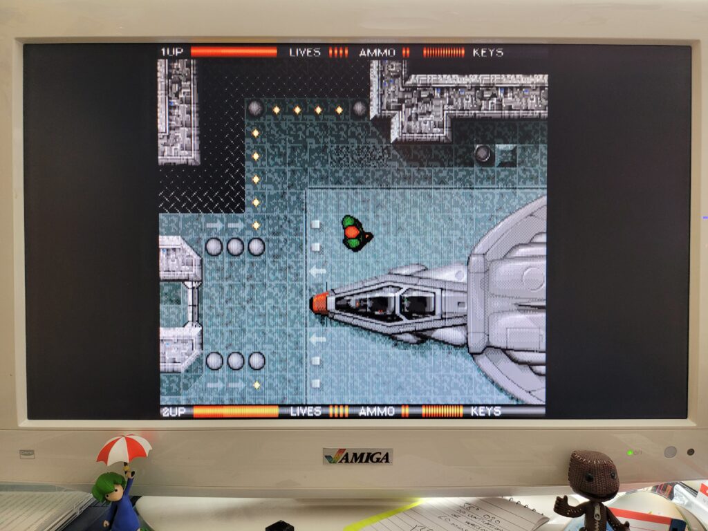
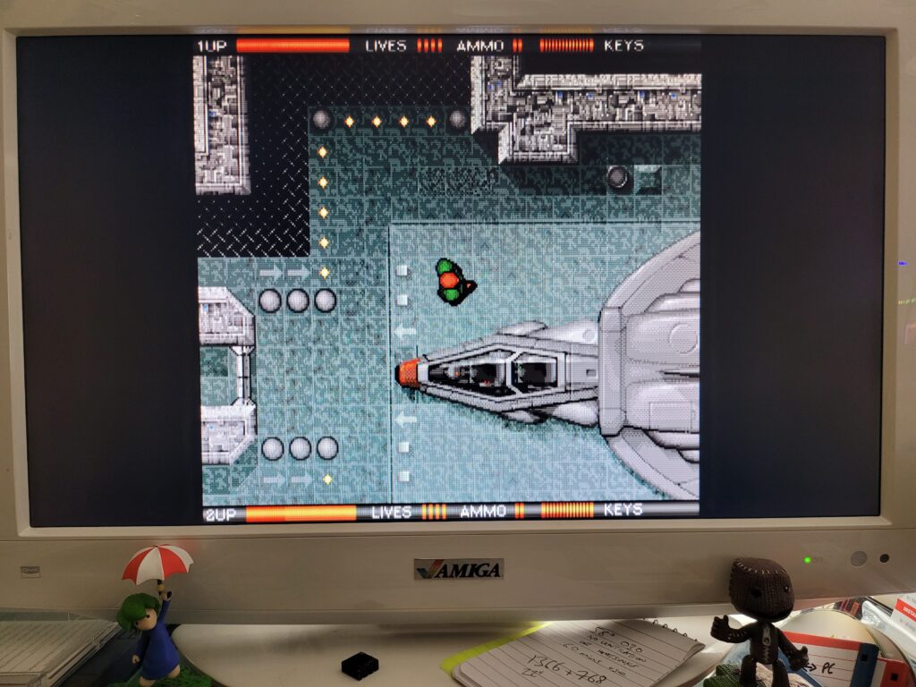
The Display Options screen allows you to select the zoom size of the screen. Some games are displayed as small 4:3 windows so you can use these settings to make the screen fit your display better. There’s also a CRT effect filter that adds scanlines to the image to make it appear as if its displayed on an old CRT monitor.


Alien Breed

WITHOUT CRT Effect.


The effect is subtle but quite effective which you can hopefully see on the two screenshots. Above is a screenshot taken without the CRT filter and below with it turned on.


Alien Breed

WITH CRT Effect.


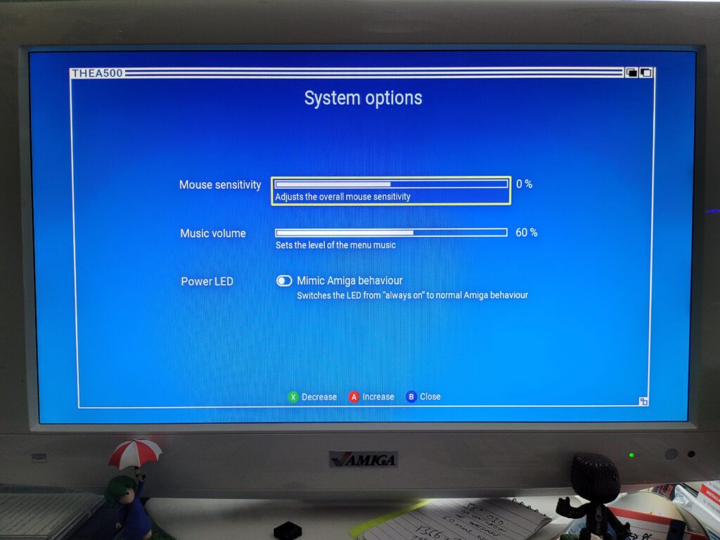
The System Options screen allows you to adjust the mouse sensitivity, music volume and Power LED behaviour. The ‘mimic Amiga behaviour’ option just made the LED act weird when loading WHDLoad games (it would keep turning off) so I left this option disabled.


The A500 Mini

System Options Screen.


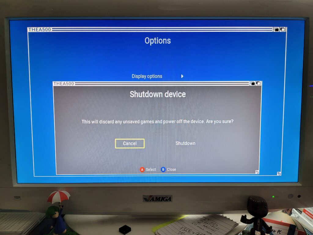
The Shutdown Device option allows a safe way to shutdown the A500 Mini and will probably be my go-to method for powering it off. If I invest a lot of time into a game and save my progress I don’t want to come back and find it’s been corrupted due to me pulling out the plug!


The A500 Mini

Safe Shutdown.


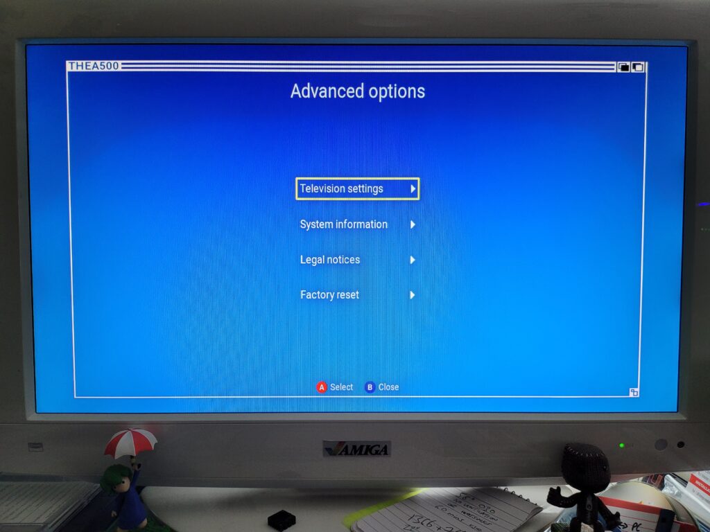
There’s also an ‘Advanced Options’ screen which is home to some less frequently needed settings. Here you can re-visit the 50/60Hz mode options, tweak whether a game should utilise the ‘border’ section of the screen, access System info, creator credits and also perform a factory reset.


The A500 Mini

Advanced Options Screen.


Loading Your Own Games

One of the advertised features of the console is being able to play your own selection of games on the device. However this isn’t explained at all in the Quick Guide, for this info you need to head online to their website: THEA500 Mini support (retrogames.biz)

In a nutshell these are the requirements for getting your own games onto The A500 Mini.

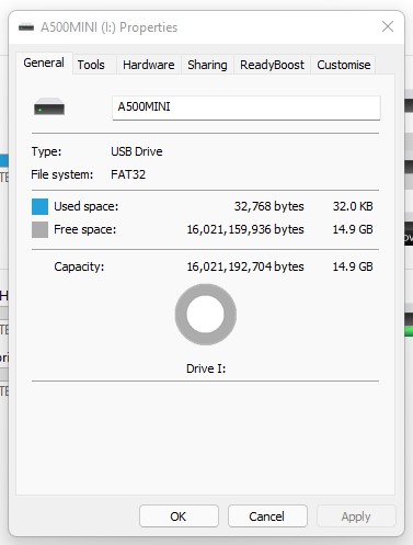
  • A USB stick formatted using FAT32.
  • The USB stick must have ‘THEA500 WHDLoad Package’ installed on it.
  • The WHDLoad programs all have to be LHA files.
  • The WHDLoad programs must be a complete archive of the program and
    not just the program’s WHDLoad installer.


My FAT32 Formatted 16GB USB Stick.


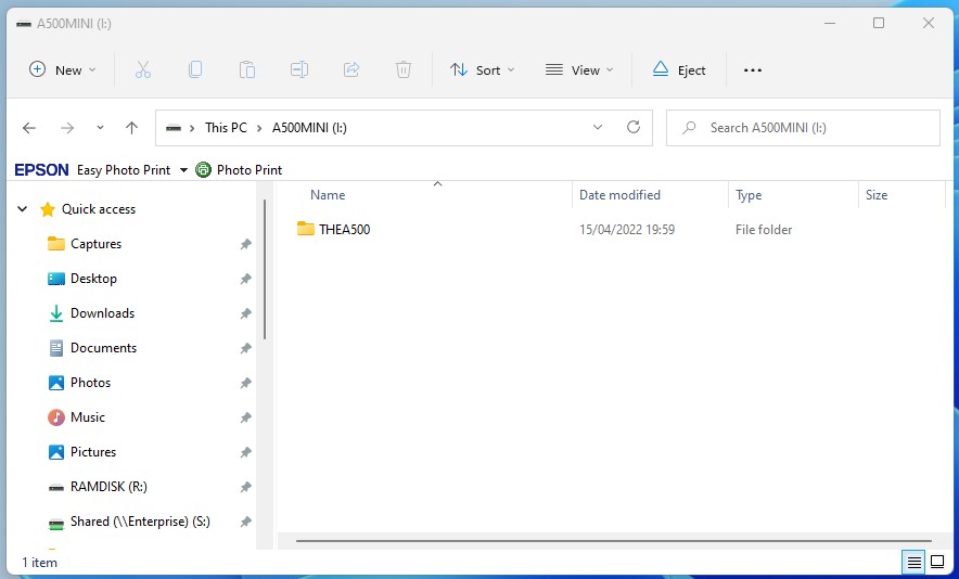
Once you’ve downloaded the ‘THEA500 WHDLoad Package v1.0.1 ‘ you simply unzip it to the ROOT of your USB stick. It should look like the screenshot below if you’ve done it correctly.


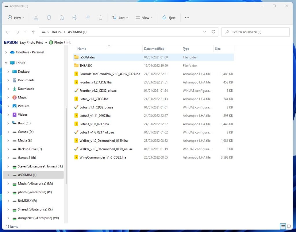
Games are simply copied into the root of the USB stick as well, or if you have a lot then you can also organise them into directories too. All the games must be in LHA format. I put a handful of games on my stick and it looked like the screenshot below. Note the ‘states’ directory and the various .uae files. These were all created by the A500 Mini itself and contain the save states and configuration options for my custom games. Don’t delete these files!
 

My USB Stick with a bunch of games ‘installed’.


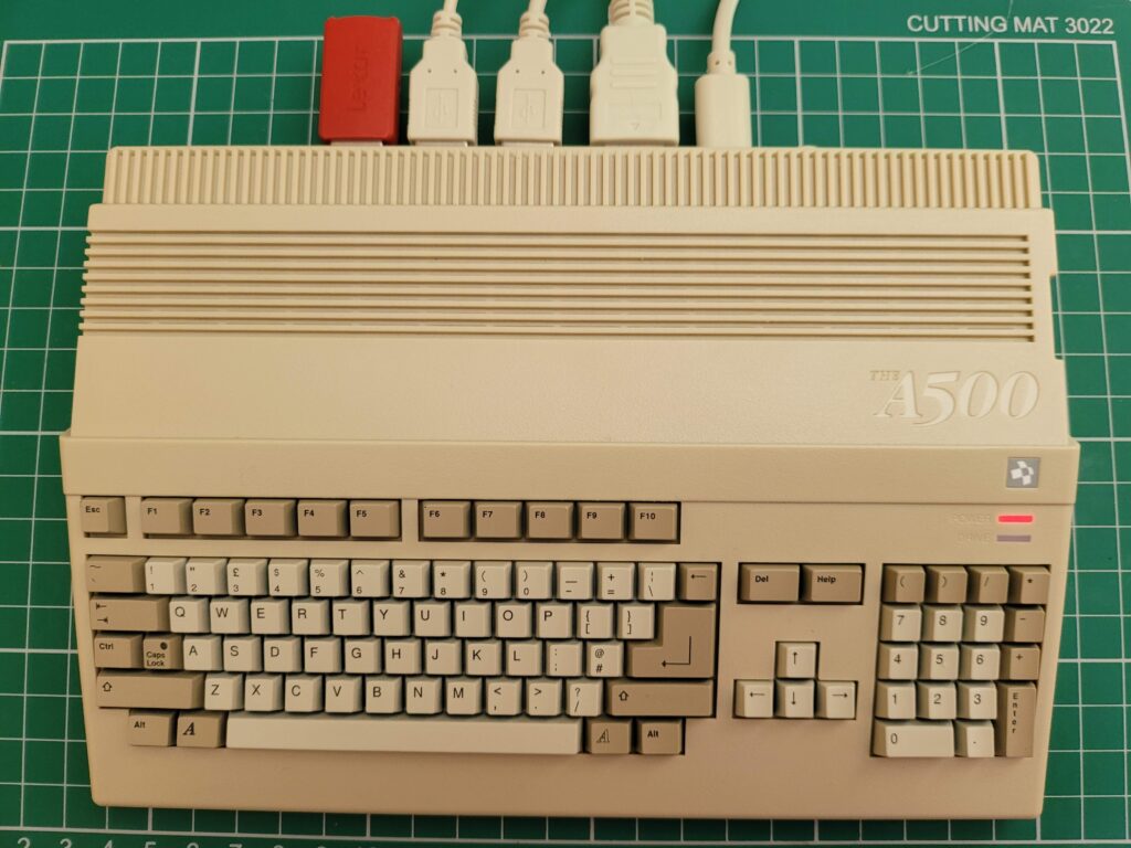
The USB stick plugs into the spare USB port at the rear of the A500 Mini – assuming you aren’t using a USB keyboard of course.


The A500 Mini

A500 Mini with USB Stick plugged in.


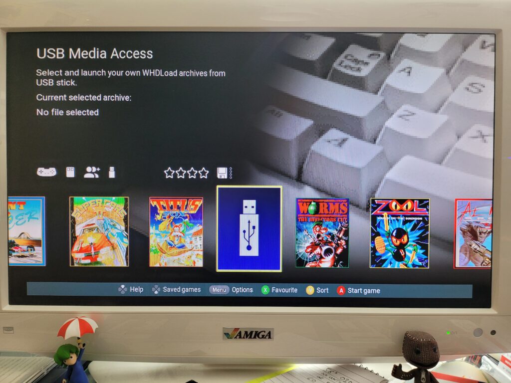
If it has been setup correctly then a USB Stick icon should appear on the carousel as shown in the photo below.
 

The A500 Mini

USB Stick icon on the carousel.


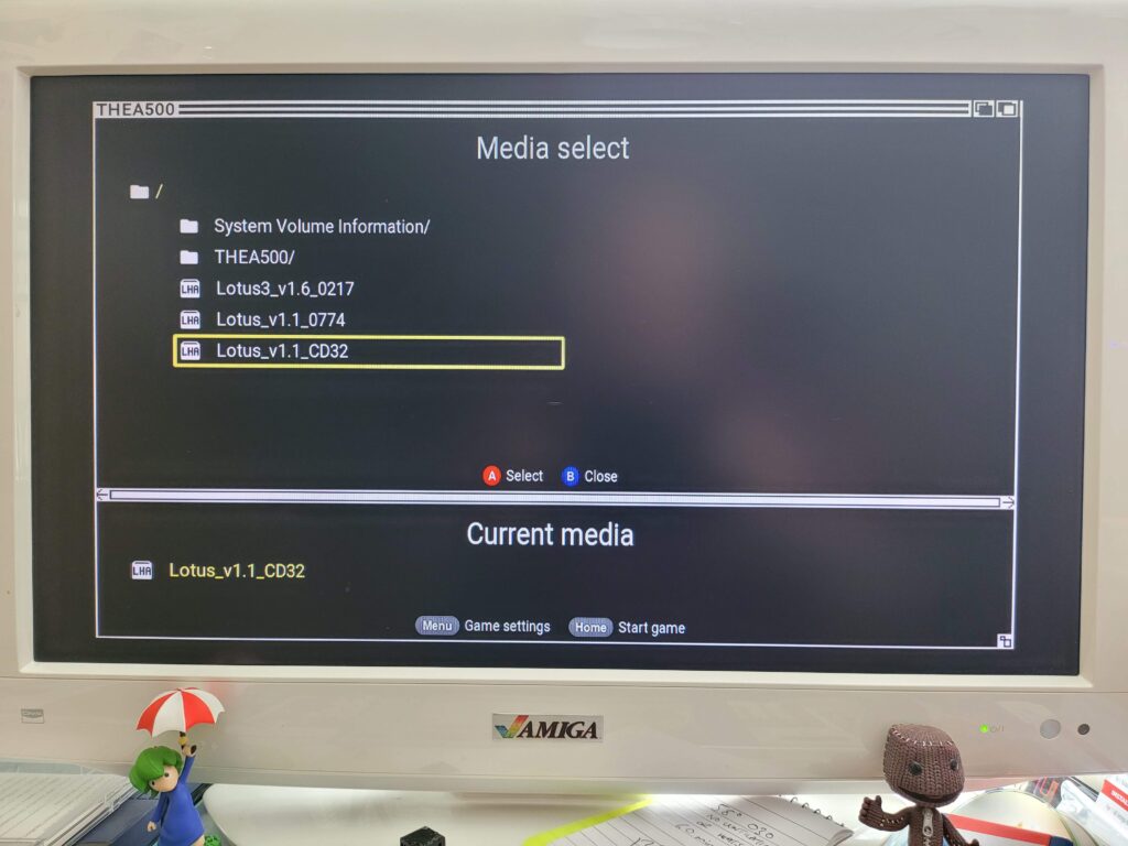
Clicking ‘Start Game’ will then bring up the contents of the stick. In my example below I had put a few Lotus games on my USB stick to experiment with.


The A500 Mini

Selecting a custom game.


When loading the games the drive activity LED finally sprang into life!


The A500 Mini

The A500 Mini Drive activity light.


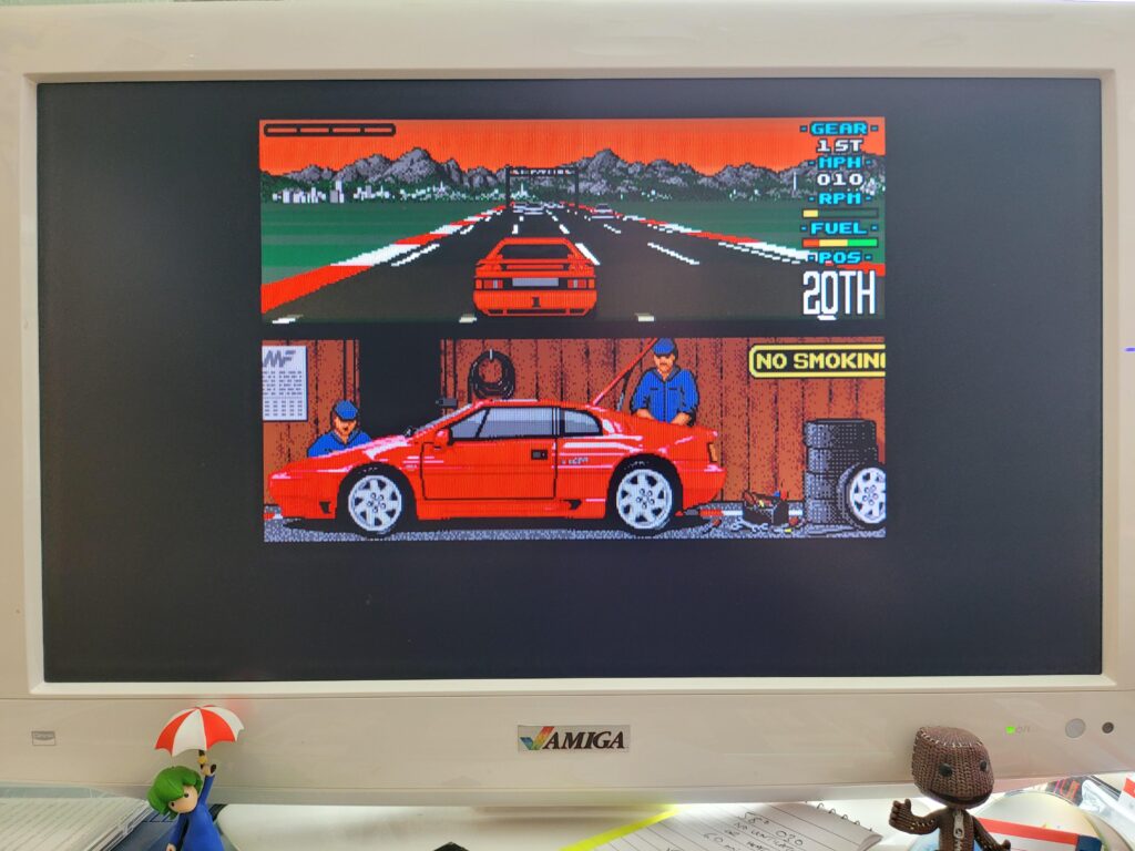
Lotus 1 loaded up and played just fine, but it was only using a fraction of the available screen space…


Lotus Turbo Esprit Challenge.


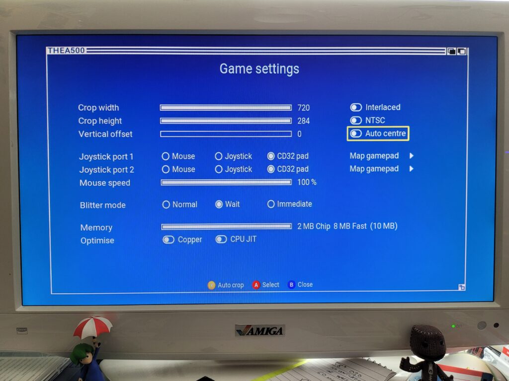
The Game Settings screen offers numerous tools to tweak how the game runs, including how it appears on screen.


The A500 Mini

Game settings screen.


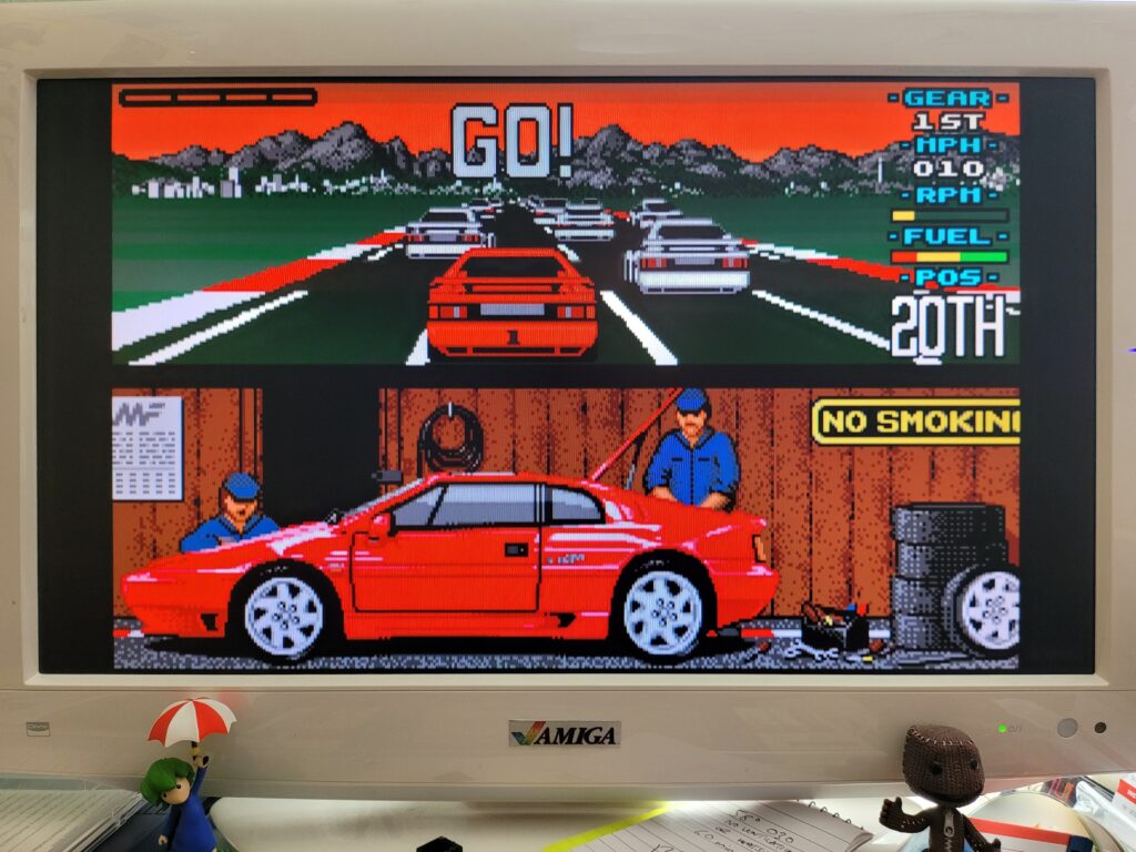
By using a combination of auto-centre and auto-crop I was able to achieve the result in the next photo which was infinitely better. These settings are remembered for each custom game too which means once you’ve only got to configure things the way you like then the one time.


Lotus Esprit Turbo Challenge looking much better now that it’s using most of the available screen.


Mouse support is disabled by default which I discovered when I loaded up Walker for a quick blast. This was easily solved by going into the Game Settings screen and enabling the Mouse on Joystick Port 1. I also had to adjust the sensitivity as it seemed way over-sensitive to me. Once I’d sorted those two things it played perfectly.


Walker.


I’m not sure exactly how powerful the A500 mini is but it’s definitely much faster than a stock Amiga 500 that’s for sure. Here’s a video of it running the intro from Frontier Elite 2. Anyone who has seen this running on a stock A500 will know that it really struggles to keep up the framerate during most of this 3D animated sequence. The A500 Mini on the other hand makes it seem effortless.


Wing Commander also ran super smooth too which I remember being another game that really needed a decent CPU to shine. It actually runs better on the A500 Mini than it does on my TerribleFire 330 equipped CD32 which has a 50Mhz 68030 CPU.


ADF Support

You may have noticed that I’ve made no mention of loading ADF disk images so far and that’s because they are simply not supported. I have to say that this is a huge disappointment for me personally as I’ve purchased a lot of modern day Amiga games and many of them only came in ADF format. I’ve also converted many of my old original physical game disks into ADF images and I’m unable to use any of them. Furthermore I have no idea how to create WHDLoad versions of any of my games so I am faced with either not being able to play these games on the A500 Mini or having to search around to see if anyone else has created WHDLoad versions of them. I really hope Retro Games Ltd. add this feature in a firmware update soon as it really limits the devices appeal at the moment for me personally.

Verdict

The A500 Mini is a beautifully designed and executed piece of kit and it seems evident to me that the guys who created it are passionate Amiga fans. The UI is beautiful and I love the slick implementation of save-states and simple to configure options to tweak my gameplay experience. The mouse and controller both look the part and work really well. Most importantly of all, the games appear to run great on the device and at an improved frame-rate too, for games that support it. The lack of a decent printed manual is a bit disappointing but hardly a deal-breaker. The lack of ADF support on the other hand is a bit more troubling and quite a let-down for me personally. If using ADF images is important to you too then maybe hold off until Retro Games Ltd. announce they’re going to add support for them. For anyone else thinking of taking the plunge though, just get one – you won’t regret it.

Amiga 1200 ‘Triple LED’ Adapter Kit

Amiga 1200 Triple LED Kit

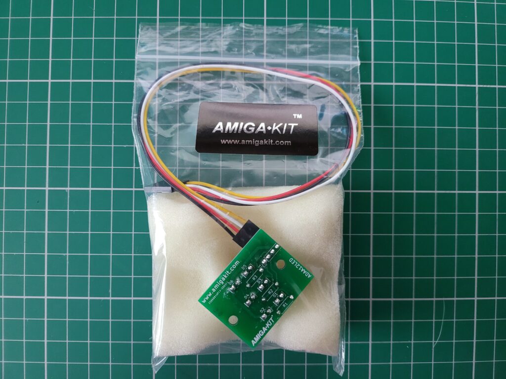
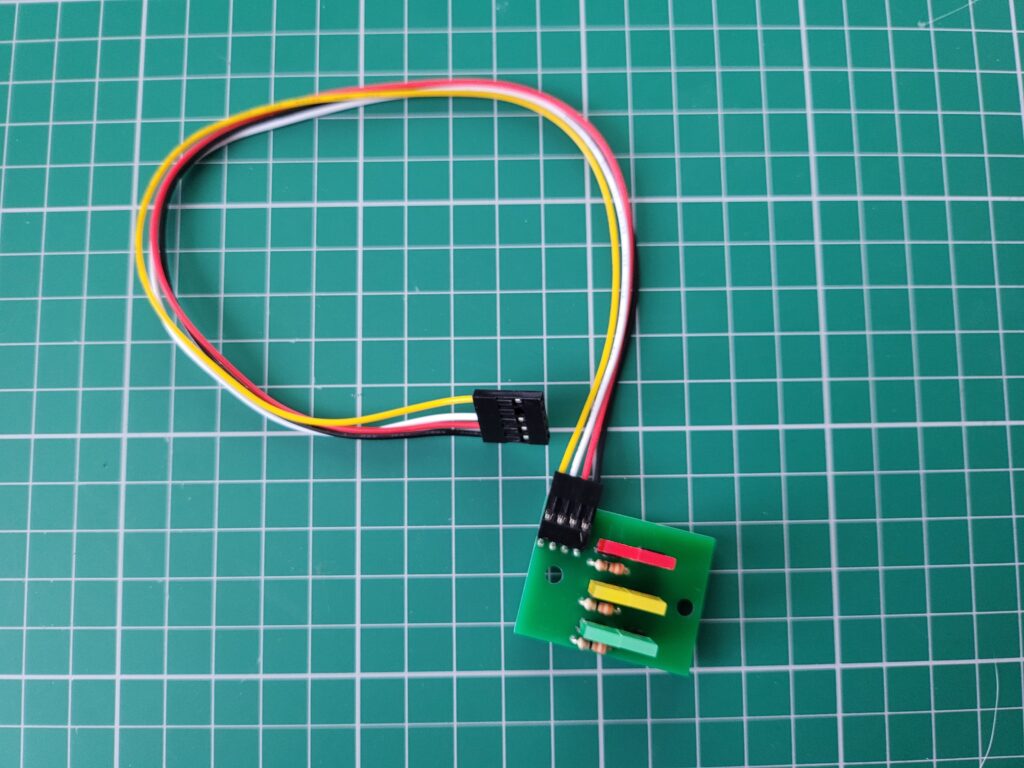
I recently spotted a neat little bit of hardware over on the AmigaKit website (they call it an ‘A1200 Triple LED Adapter’) that allows the user to change the colours of the Amiga 1200’s activity LED’s. A quick impulse purchase and a few weeks later the kit arrived, well packaged and protected in a zip-lock bag with a wad of foam to stop the LED’s from being damaged.


A1200 Triple LED Adapter

A1200 Triple LED Kit Packaging.


A Closer Look at the A1200 Triple LED Adapter

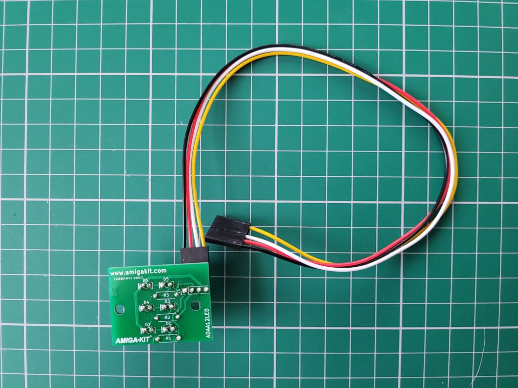
The adapter actually offers a number of small improvements over the Amiga 1200’s stock LED’s.  For a start the connector cable now incorporates a 4-pin plug that can easily be removed from the LED circuit board. This will be a real boon when opening up my A1200 in the future allowing the case lid to be removed easily without straining the soldered wire connections.


A1200 Triple LED Adapter

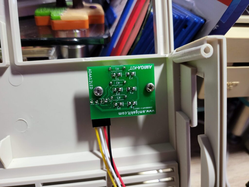
Back view of the A1200 Triple LED Kit.


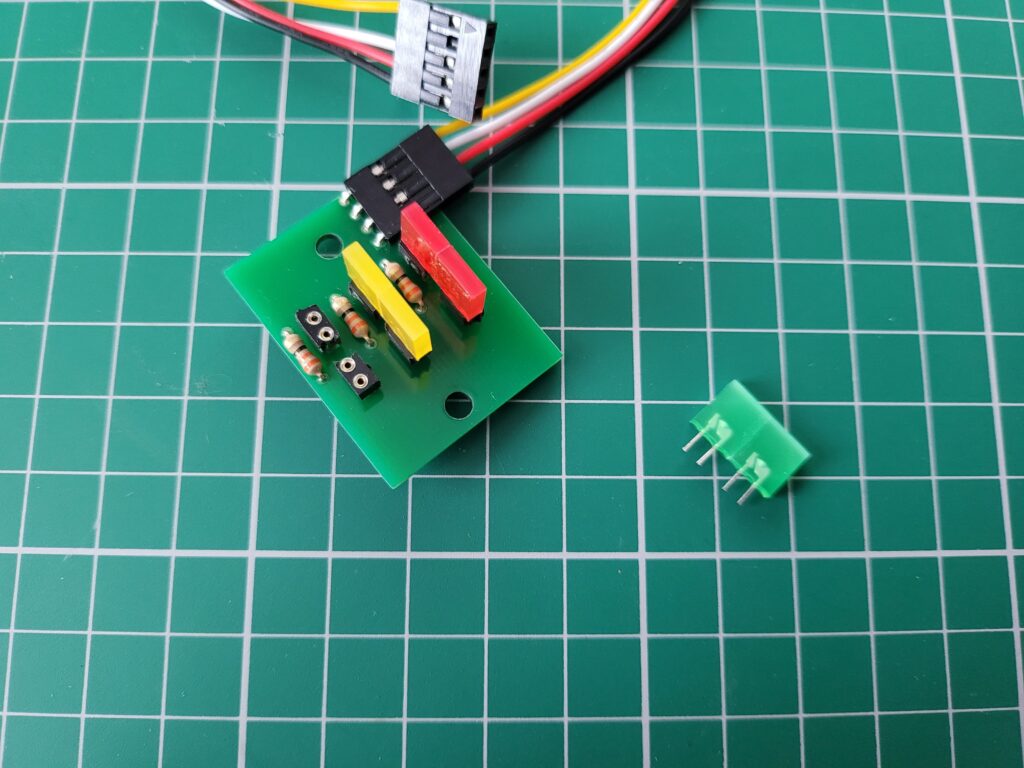
The biggest benefit though is that the LED’s are now removable and completely interchangeable. When selecting the kit on AmigaKit’s website you can pick what colour you want each LED to be. I chose Red, Amber and Green to represent HDD, FDD and Power activity respectively. They sell spare LED’s too in case you should need them in future which is good to know.


A1200 Triple LED Adapter

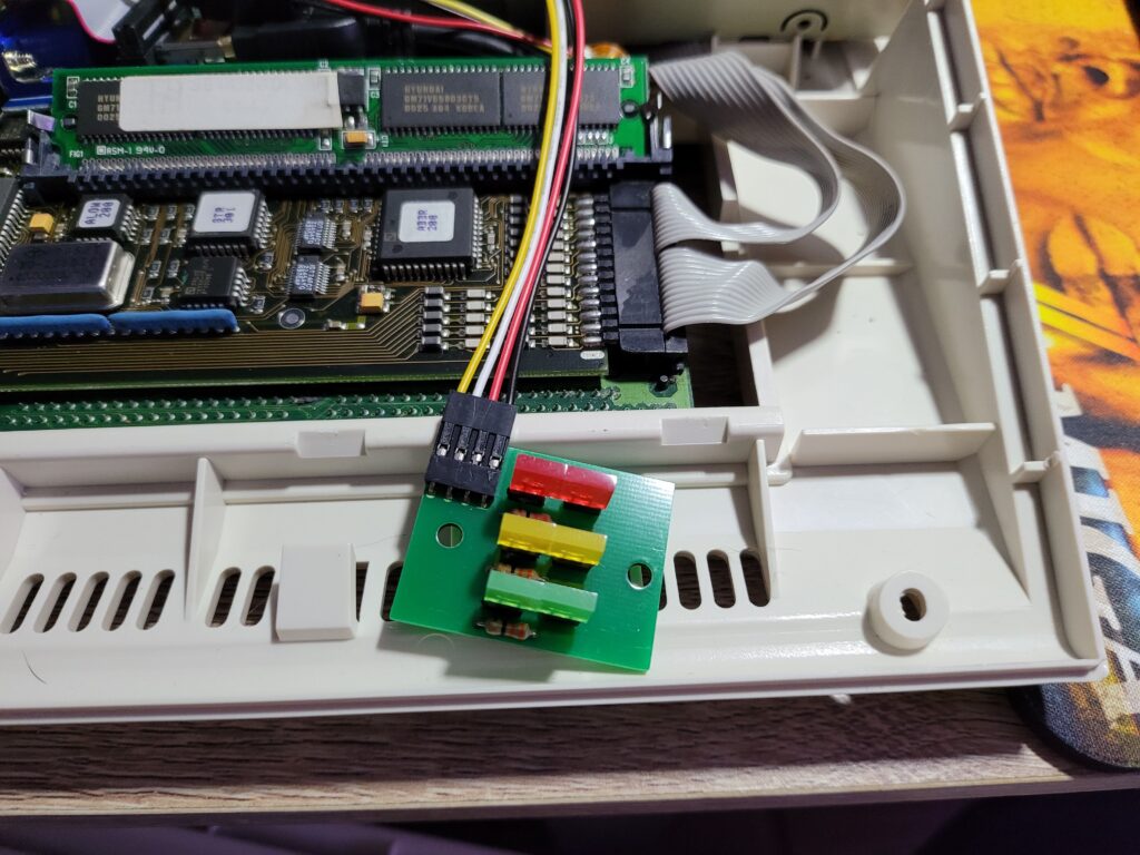
Here you can clearly see the 3 coloured LED’s.


The LED’s are all socketed and they can be removed by simply pulling on them gently so if you change your mind and want a yellow power LED – no problem!


A1200 Triple LED Adapter

A1200 Triple LED Kit with one of the LED’s removed revealing empty socket.


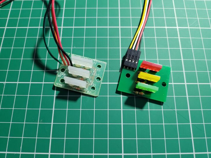
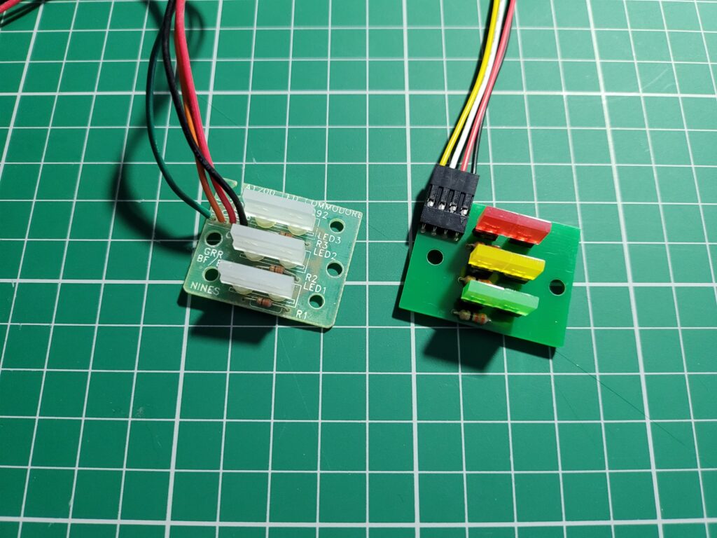
In the photo below you can clearly see the difference in the LED’s. The original A1200 board features transparent LED’s that light up pale yellow/orange/green colours when powered. By contrast the new board has coloured LED’s that I think provide deeper and more pleasing colours when illuminated.


A1200 Triple LED Adapter

Original LED board on the left, new one on the right.


Fitting the Kit

Fitting the new LED’s couldn’t be any simpler really. Start by removing the two phillips screws holding the old board to the case. Keep them safe as they will be needed to fix the new board in place shortly.


A1200 LED board

Original LED board attached to case with two Philips screws.


Unplug the power LED from the A1200’s mainboard. In the photo below it’s the lower (black) connector. The white connector is for the floppy drive. The old board can now be completely removed and stored away safely in case you ever want to put it back.


Amiga 1200 mainboard

Amiga 1200 original LED power connector on mainboard (the lower of the two).


Fitting the new board is basically the same procedure in reverse. Start by connecting the power cable to the board. The colouring is slightly different with the new wiring but just make sure the black cable goes on the left (below photo).


Amiga 1200 mainboard

Amiga 1200 new LED power connector on mainboard (the lower of the two).


Before fitting the board to the case make sure you orient it correctly; the power cable connects to the top of the board. Don’t forget to thread the cable through the square hole in the metal keyboard frame too!


A1200 Triple LED Adapter

New triple LED adapter connected and ready to be attached.


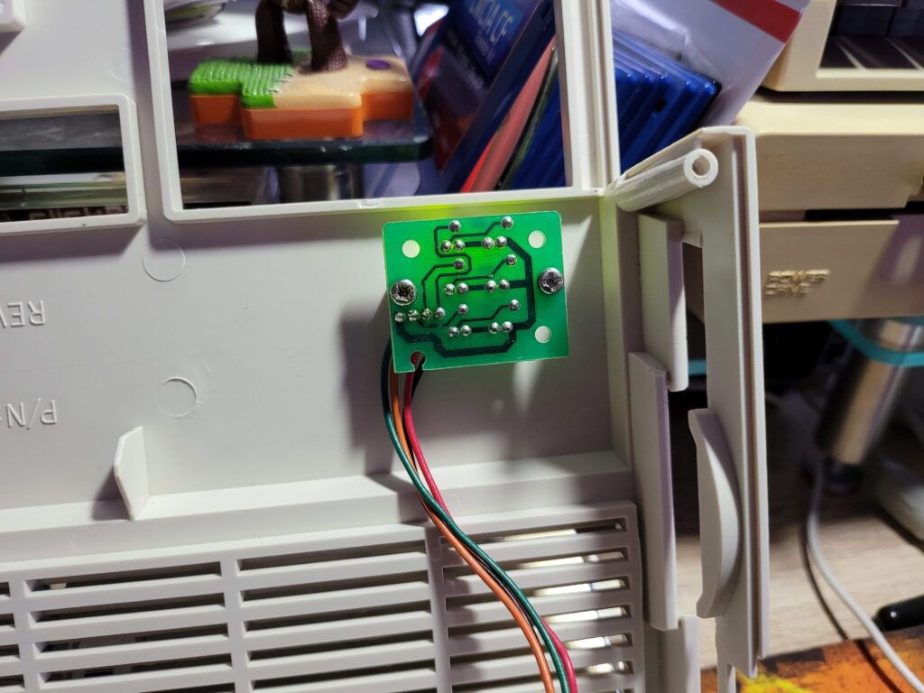
Attach the board using the two phillips screws that you removed earlier. The correct board orientation can be seen in the photo below.


A1200 Triple LED Adapter

New A1200 Triple LED adapter attached to A1200 case lid.


At this stage it might be worth a quick power up to check that the LED’s are working. Assuming all is good, carefully reassemble the case and the upgrade is complete. If not, check the connector is pushed all the way down onto the pins and that it’s oriented correctly.


Finished Result

I found the new LED’s to be ever so slightly narrower than the original ones so there’s a tiny gap left on either side of them. However it’s hardly noticeable, especially once they’re actually illuminated.


A1200 Triple LED Adapter

LED kit fully fitted.


I recorded a quick video to demonstrate what the drive activity LED’s look like in use. I’m very happy with the results and would definitely recommend this kit to anyone that wants to spruce up their A1200 a bit.


A1200 PCMCIA Reset Bug – Hardware Fix

PCMCIA Reset Fix

The A1200 PCMCIA reset bug is an annoying glitch in the implementation of the card slot on the A1200 that was never fixed by Commodore. In a nutshell the Amiga 1200’s Gayle chip fails to reset PCMCIA cards during system resets such as when you press ‘CTRL A A’. Whether this is an issue for the user largely depends on the card being used but my network card is definitely one of those that is affected by the bug. Without either a software or hardware fix it requires a full power cycle to restore card functionality every time the bug manifests.

I’ve written about this issue before where I described fixing it using two command line programs called CardPatch & CardReset on Aminet. That software solution served me pretty well up until recently when I ran into the issue again after doing a clean AmigaOS3.2 install. After scratching my head wondering why Roadshow wasn’t working I decided it was time for a permanent hardware fix so that I would never encounter the issue again.

My Hardware Fix

A quick browse around my favourite Amiga suppliers revealed that AmigaKit made one such device and they had it in stock. Fast forward a couple of weeks and I had one sitting on my desk.

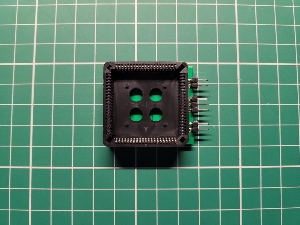
The adapter consists of a PLCC socket attached to a small circuit board that contains the electronics for the fix.


A1200 PCMCIA Reset Bug

AMIGAKIT A1200 PCMCIA Reset Bug-fix Adapter (PLCC socket side).


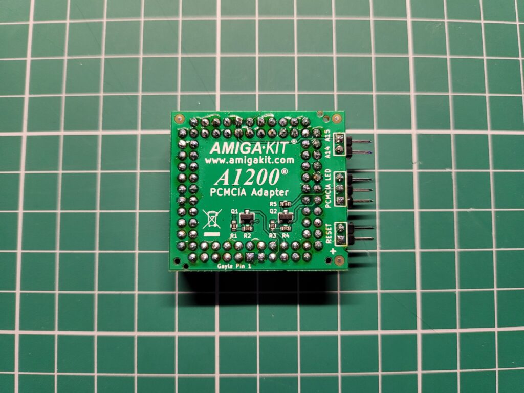
Besides the reset bug fix the device also includes pin headers for attaching a reset switch, a PCMCIA activity LED and also A14 and A15 signals for other devices such as clockport expanders. It’s a well made, neat little device.


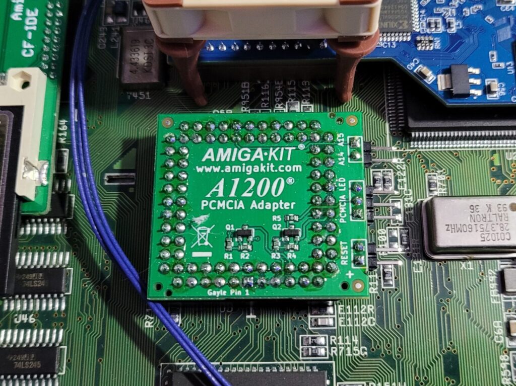
A1200 PCMCIA Reset Bug

AMIGAKIT A1200 PCMCIA Reset Bug-fix Adapter (circuit board side).


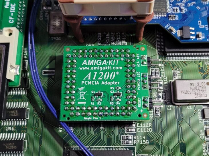
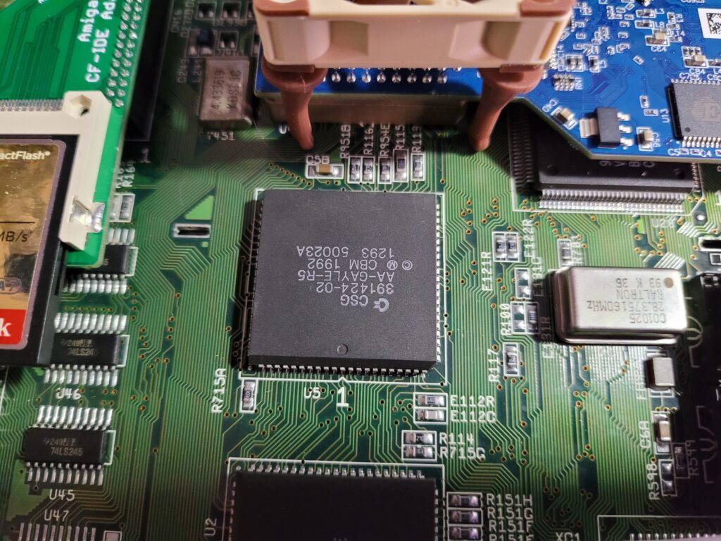
The device is designed to sit on top of the A1200’s ‘GAYLE’ chip which is where the fault stems from.


Amiga 1200 GAYLE chip (centre of the photo).


Installing the Adapter

To install the hardware fix you simply place the PLCC socket over the top of the GAYLE chip. However before doing this you must make sure that the device is oriented correctly otherwise it won’t work and may even damage your Amiga.

The adapter circuit board has ‘Gayle Pin 1’ written along the bottom edge and if you look closely on the A1200 mainboard below the Gayle chip you will see a ‘1’ marked beneath it (when viewing from the front). Make sure that these two are on the same side. Another, probably easier, way to tell is that the writing on the board should be the right way up once installed (viewing from the front). The pin headers should point towards the right hand side of the machine where the floppy drive is and away from the PCMCIA port too.

It takes a some force to get it to seat properly and the top of the board is not particularly finger friendly so be careful. It should click into place securely and not wobble around at all.


PCMCIA Reset Fix

AmigaKit PCMCIA Reset Fix installed on the Gayle chip. Note how ‘Gayle Pin 1’ on the adapter lines up with the ‘1’ on the mainboard.


There’s nothing else to connect and no software to install. Once the device has been installed you can close up the A1200’s case and switch it on.


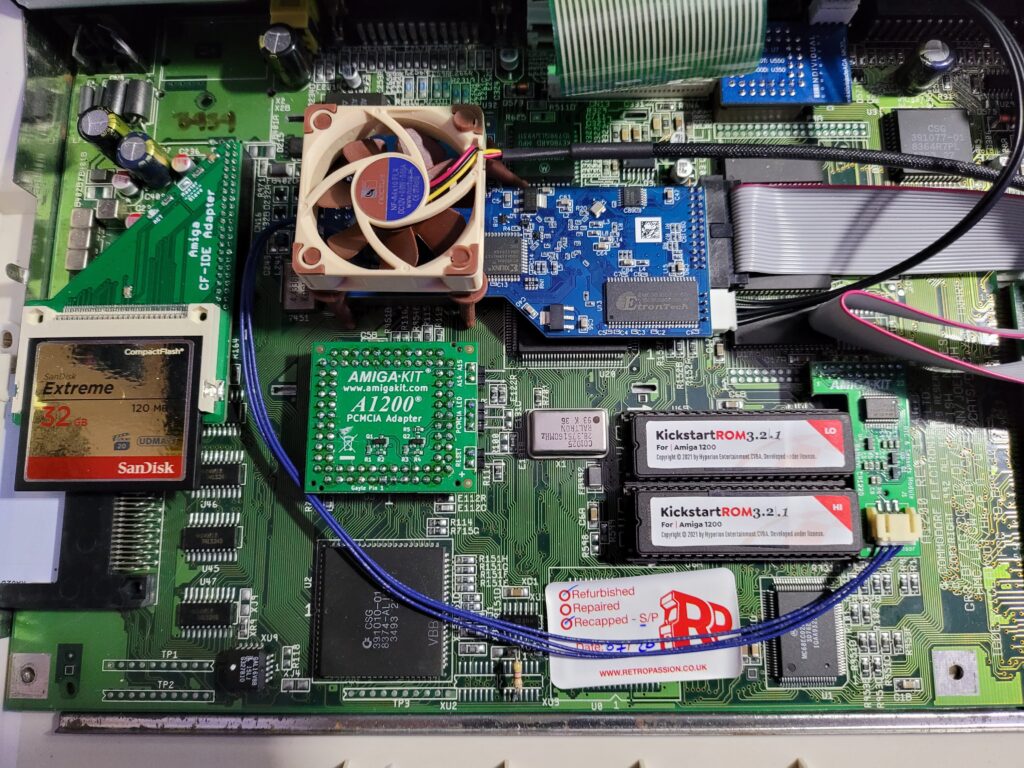
A1200 PCMCIA Reset Bug

My Amiga 1200 mainboard sporting a number of extra expansions.


If everything has gone to plan the Amiga will boot up normally with no visible signs that anything has changed… except that PCMCIA cards will just work as intended now. No more unresponsive network cards after a reset from now on then!

I’ve had the device fitted for a week now and experienced no issues with my cards since. It does exactly what it says on the tin.

The expansion pin headers on the board are an interesting addition. I’ll probably add a reset switch to it in the near future as that would definitely come in handy. Not sure about the PCMCIA LED as I don’t use my CF adapter that often.

Anyway, if  you are coming up against the A1200 PCMCIA reset bug and want a ‘fit and forget’ solution I highly recommend this; it’s cheap, easy to fit and does the job.

Upgrading to AmigaOS 3.2.1

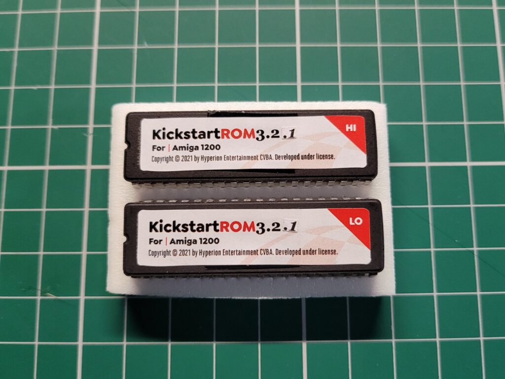
Kickstart 3.2.1 ROMS

I’ve not even had my Kickstart 3.2 ROMS installed in my Amiga 1200 for a month and I’m already replacing them! Why? Because AmigaOS 3.2.1 was released by Hyperion in December 2021. This incremental update fixes a number of issues and also adds a few new features so naturally I wanted to get my hands on it. Strictly speaking the physical ROMS are not required as you can map copies of them into RAM. However I wanted the real deal so ordered a set from AmigaStore.eu as this was were I bought AmigaOS 3.2 from. They arrived quickly and well packaged (along with an SDBox I ordered at the same time).


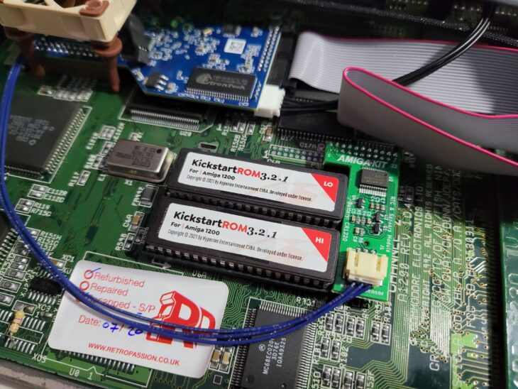
AmigaOS 3.2.1

AmigaOS 3.2.1 Kickstart ROMS for the A1200


Installing the ROMS

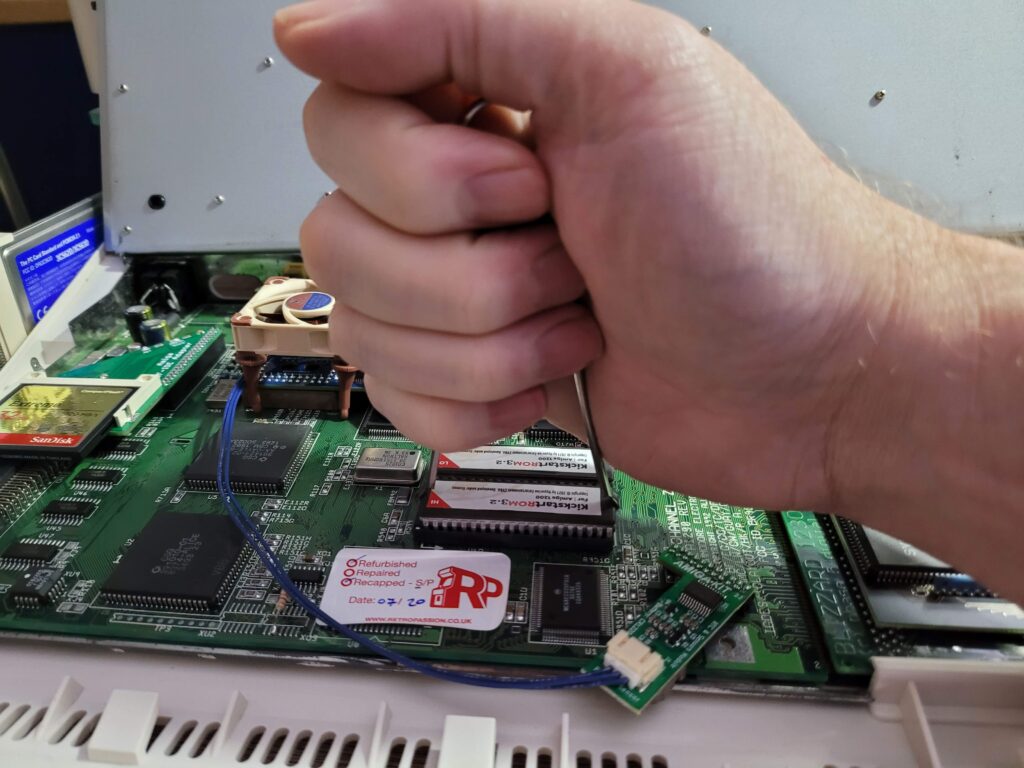
Naturally the first thing I did was to open up my A1200 and fit the two new ROM chips. If you are looking for more comprehensive instructions on how to do this you can follow my guide here. The important things are to get the ‘HI’ and ‘LO’ chips in the correct sockets, that you orient them correctly (notched end of chip goes next to notched socket) and finally that you leave the last pair of pins in each socket empty as the sockets have 42 pins whereas the ROMS only have 40.


Removing the ROMS with a chip puller.


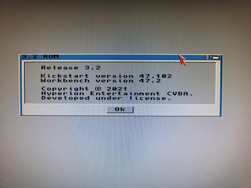
Before going any further I booted up my Amiga to make sure everything was working and that the new Kickstart ROMS were the correct version. Sure enough Workbench reported a Kickstart Version of 47.102 which is the 3.2.1 edition. Happy days.


Kickstart 3.2.1 version

Kickstart 3.2.1 (version 47.102).


Next I needed to obtain the 3.2.1 Workbench update. This is a free download from Hyperion but does require you to register your copy of AmigaOS 3.2 before it will allow you access. This requires the little code that was stuck onto the cellophane wrapper of the AmigaOS 3.2 box. The update comes in the form of a 15MB LHA archive that includes Kickstart ROMS should you need them.


Installing AmigaOS 3.2.1

AmigaOS 3.2 introduced native support for ADF image files so I thought I’d make use of this feature to update Workbench.


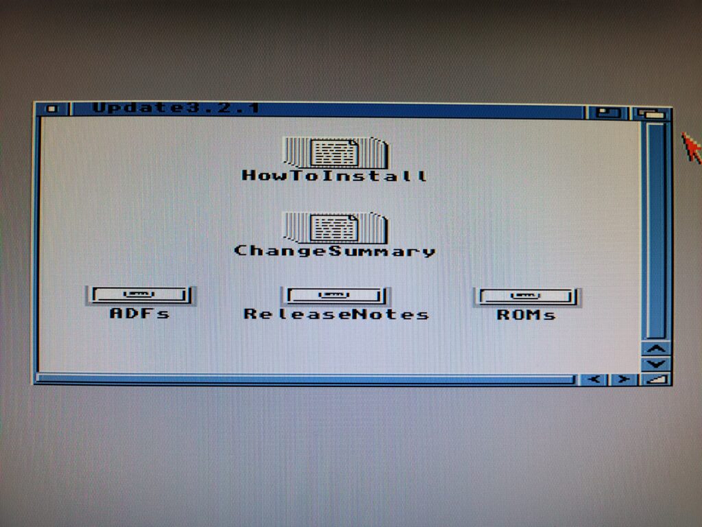
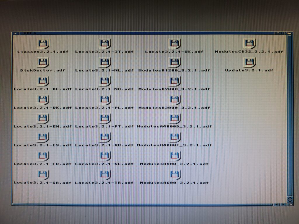
Contents of the Update3.2.1 LHA Archive

Contents of the Update3.2.1 LHA Archive


The LHA archive unpacks into a single Update3.2.1 folder that includes everything necessary to get things up and running. Opening up the ADF folder reveals 26 ADF’s and it’s these we need to do the upgrade.


Contents of the ADF Folder.


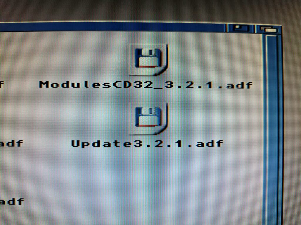
The ADF we need to get the ball rolling is called ‘Update3.2.1’. Simply double-clicking it opend that ‘disk’.


The Update3.2.1 ADF Image


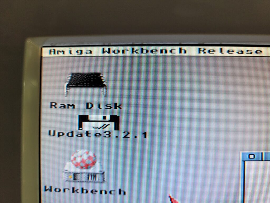
It will then appear on the desktop just as if you’d inserted it into a physical drive yourself.


It all Starts with the Update3.2.1 disk.


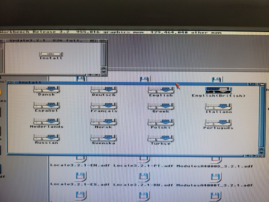
Opening that disk, and then the Install folder within it, reveals a bunch of different country-specific installers. I went for the English(British) option as I’m in the UK.


Contents of the Install Folder,


Go!

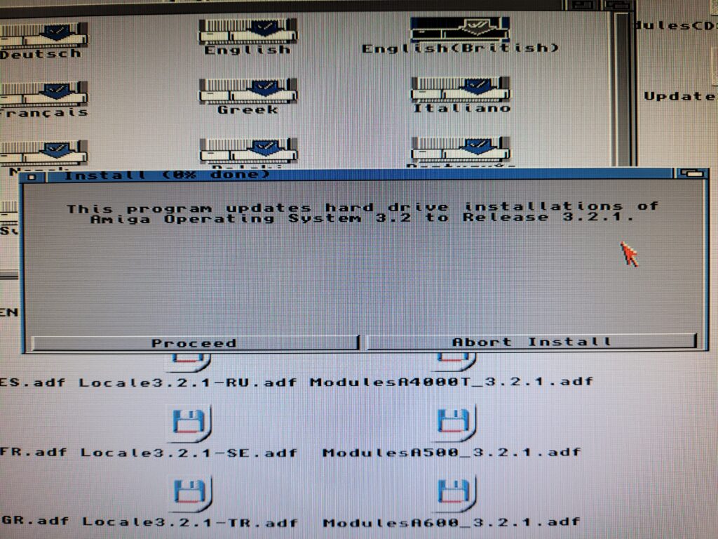
The install process is now underway and we just need to click ‘Proceed’ to begin.


AmigaOS 3.2.1 Upgrade

AmigaOS 3.2.1 Update Begins


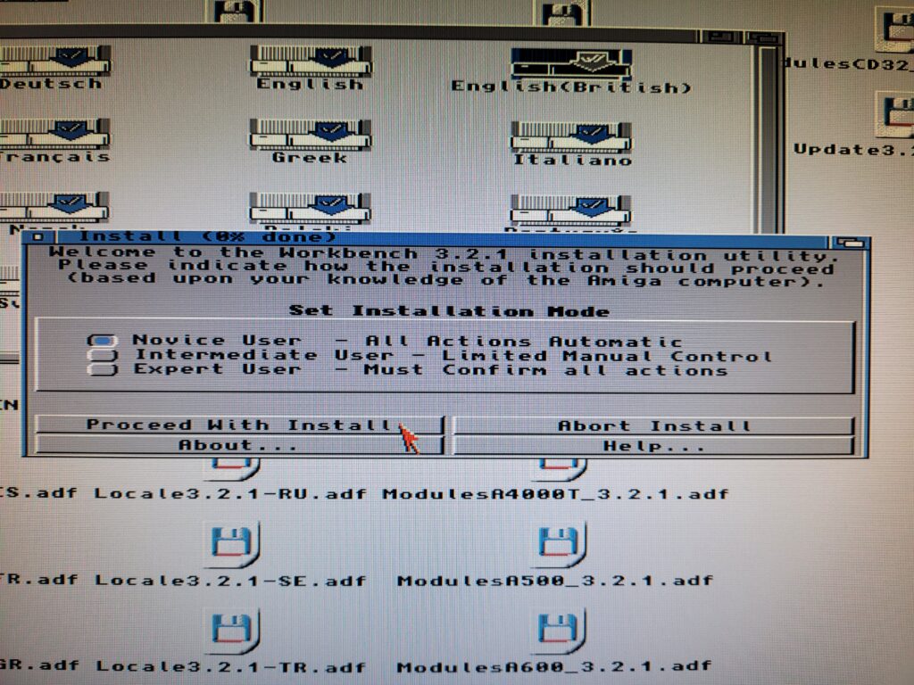
The first choice to make was picking an installation mode. I left it on the default ‘Novice User’ option as I’ve not done much customisation to my A1200 since doing a clean install of 3.2 a few weeks ago.


Installation Mode

Selecting the Installation Mode.


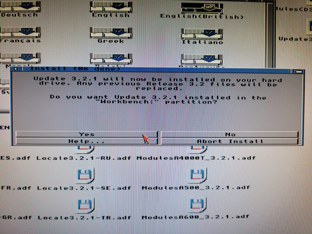
A warning pops just to confirm you are happy to proceed with the update which will obviously replace a bunch of your 3.2 files in the process. I clicked ‘Yes’ to proceed.


Installer

Confirming the start of the upgrade.


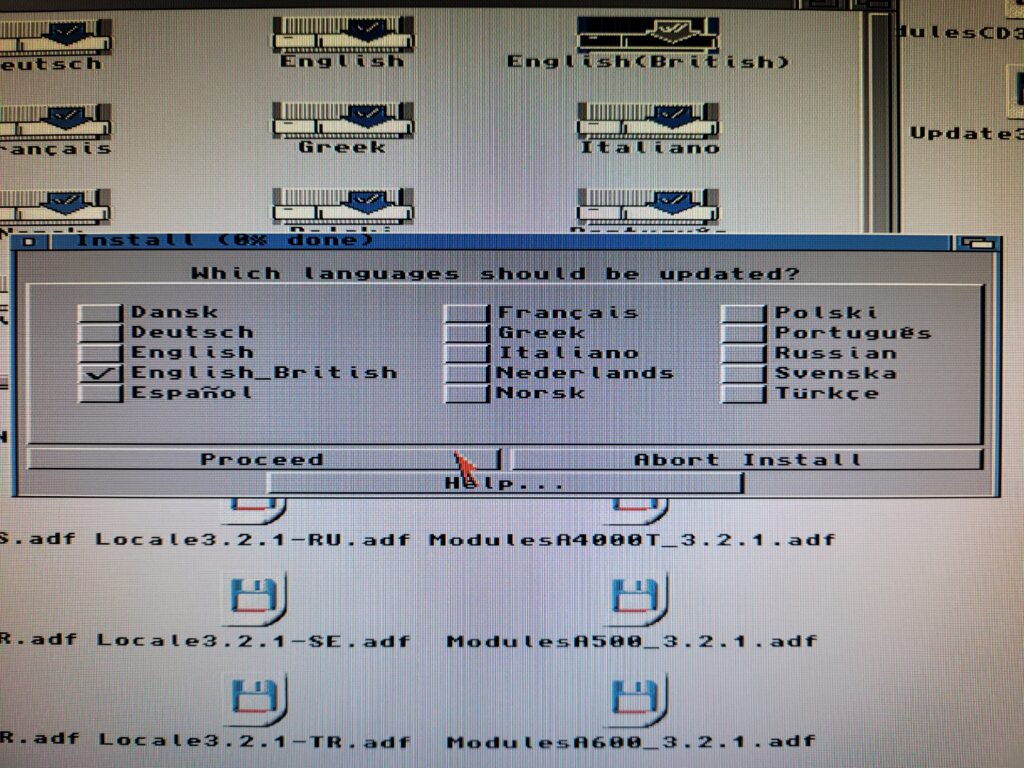
Next up you get to choose which language(s) you want. Check the boxes next to the one(s) you would like and then click ‘Proceed’.


Installer

Language selection.


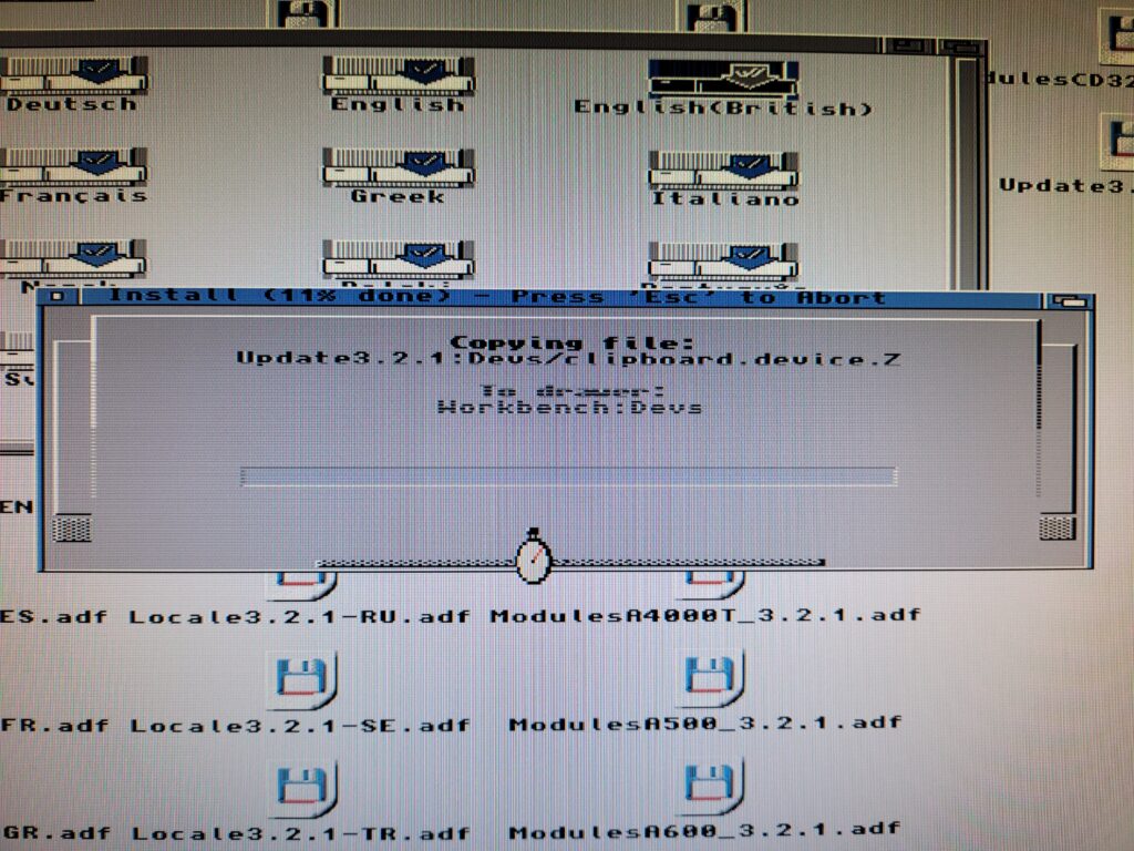
It’s at this point that the installation really starts and files get copied across.


Amiga Installer

Files copying across.


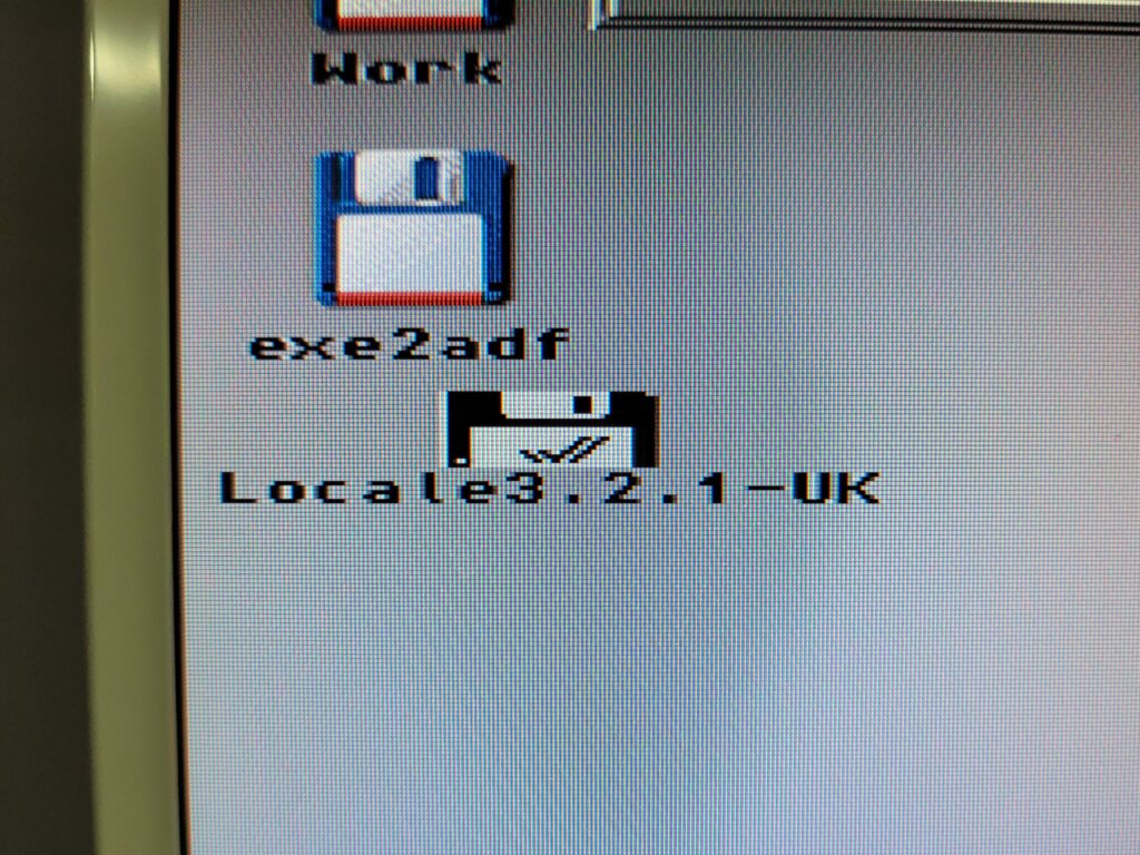
Now I thought I was going to need to select each ADF as and when the installer requested a new disk. However that wasn’t the case at all. Something pretty cool happens during the install – it mounts and unmounts each ADF image as it needs them – automatically. During the install you see a bunch of disks appear and then disappear on the Workbench like magic. Impressive stuff indeed.


Mounted ADF image file

ADF images are switched on the fly.


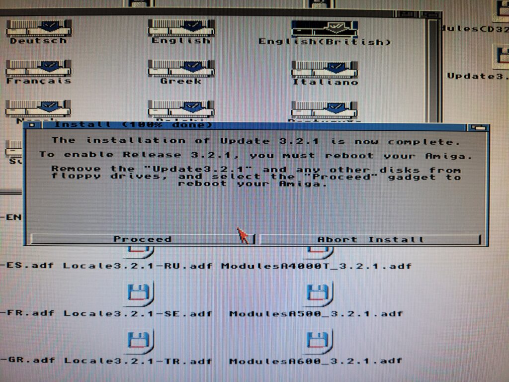
Thanks to the auto-switching virtual disks the update only takes about a minute to complete. Once finished it asks you to click ‘Proceed’ to reboot your Amiga. It was at this point that I got my second pleasant surprise – my Amiga automatically rebooted itself! Many installers have the same message at the end but I don’t recall any that actually rebooted the machine before.


Installer complete

Upgrade complete.


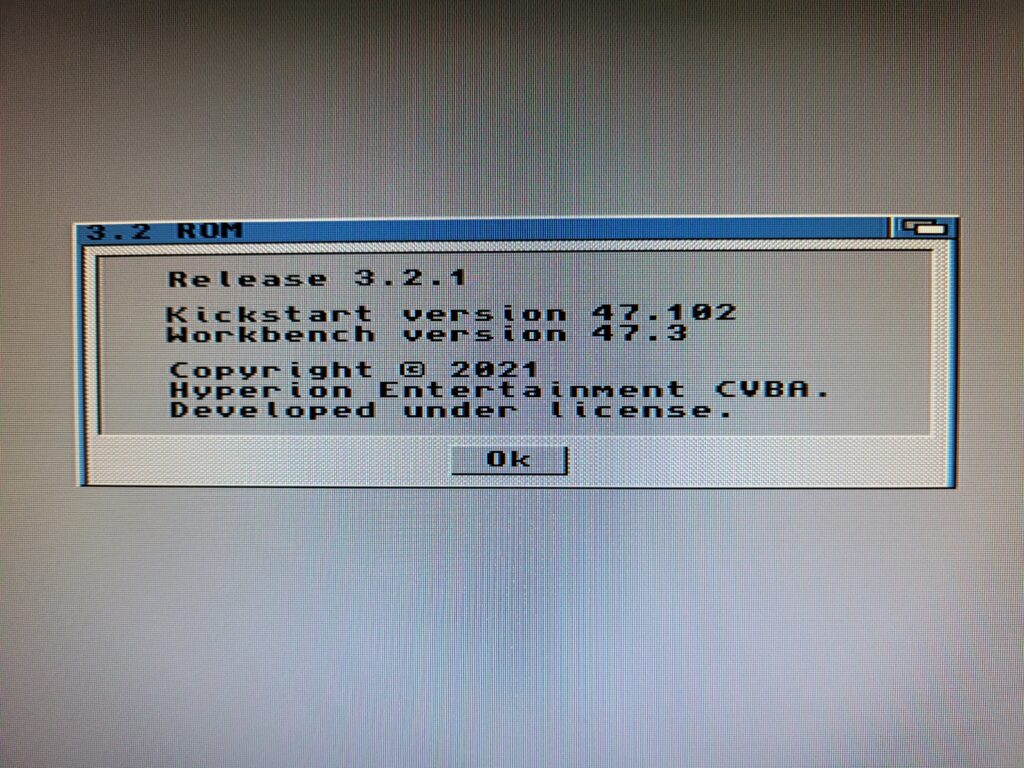
Once Workbench had loaded back up I did another quick check of the version numbers. Reassuringly Workbench was reporting being 47.3. Combined with Kickstart being 47.102 this confirmed that my upgrade to AmigaOS 3.2.1 was complete.


AmigaOS 3.2.1

Both Workbench and Kickstart displaying correct versions.


New Feature – Eject

This release includes a lot of bug fixes and a number of new features too. Out of all of them though, the one I was most excited to see was also probably the most trivial. The Amiga now has an ‘Eject disk’ option under the Icon menu! Not unsurprisingly this lets you eject any disks that supports this feature. It was probably mainly intended for un-mounting ADF images but it also works with physical drives. I tried it out on my SCSI CD drive and it worked like a charm it also worked well with my Iomega Zip drive. Sure this was possible before via 3rd party programs but to have this feature natively available in Workbench is a first and worth upgrading for alone in my book.


SDBox Review

SDBox

If there was one take-away from my recent clean install of AmigaOS3.2 it was that transferring files across to a stock Amiga system is a real pain in the arse. Sure you can use CrossDOS, but that is limited to 720K files. If you have a CD drive then you can burn stuff to a CD which raises the limit considerably to 650mb. However this is pretty time consuming and my drive refuses to read CDRW discs so means I have to use CDR’s which is downright wasteful.

Enter the SDBox – a little expansion for any Amiga system that enables it to read and write data to MicroSD Cards. A few years ago I wrote a post about adding an SD Card to an A500, however that relied on having a Vampire accelerator card. This device just requires a parallel port to operate, something which all Amiga’s have.

What’s Included

The SDBox is actually a public domain Amiga community project that you can construct yourself (see here). However due to the inclusion of some surface mount components I chose to buy one ready made from Amigastore.eu. I can normally solder stuff OK but dealing with tiny surface mount components is beyond my skill level.


SDBox

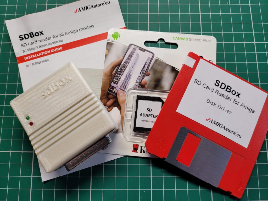
SDBox – package contents.


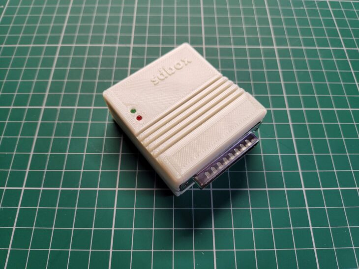
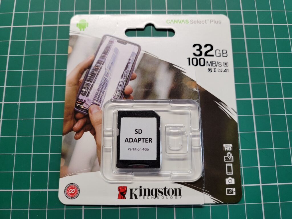
Included in the package was the SDBox device in a nice 3D Printed case, a 4GB MicroSD Card with adapter*, instruction booklet and a 3.5″ floppy containing the software to make it all work. A mini USB cable was an option too but I’ve accumulated dozens of them over the years so didn’t see the point in getting another one.


Connecting the SDBox

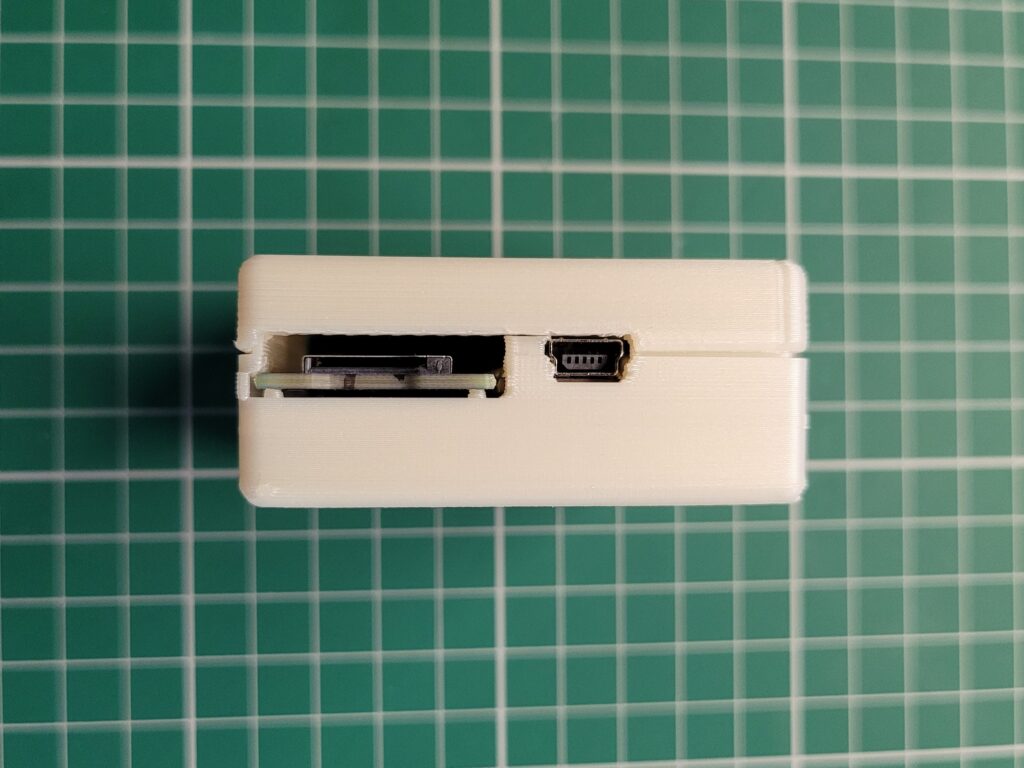
With the Amiga turned off the SDBox simply plugs into the parallel port socket round the back. It also requires 5V of power to function which can be provided via a mini USB cable.


SDBox

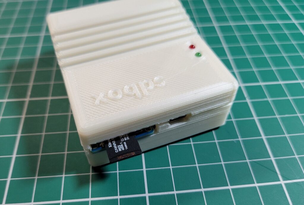
The Micro SD card slot and Mini USB power socket on the back of the SDBox.


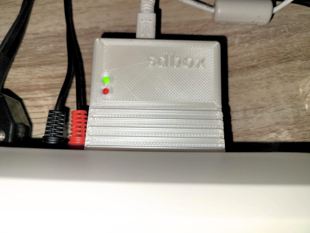
I found there was just enough clearance at the side for it to not interfere with my RCA audio plugs but this might not be the case if you have thicker plugs.


SDBox

The SDBox plugged into the parallel port.


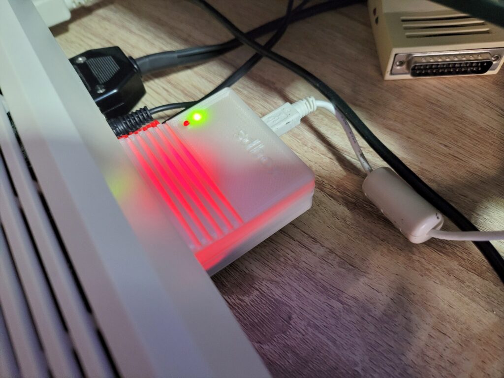
When powered on the box glows red from inside – presumably this illumination comes from an LED on the Arduino Nano. It’s not quite as noticeable as the photo below would have you believe and it’s not a big deal.


SDBox

Red glow from the Arduino Nano inside.


Installing the Drivers

With the hardware powered on and connected the next task is to pop in the floppy and run the installer to install the driver software.


SDBox

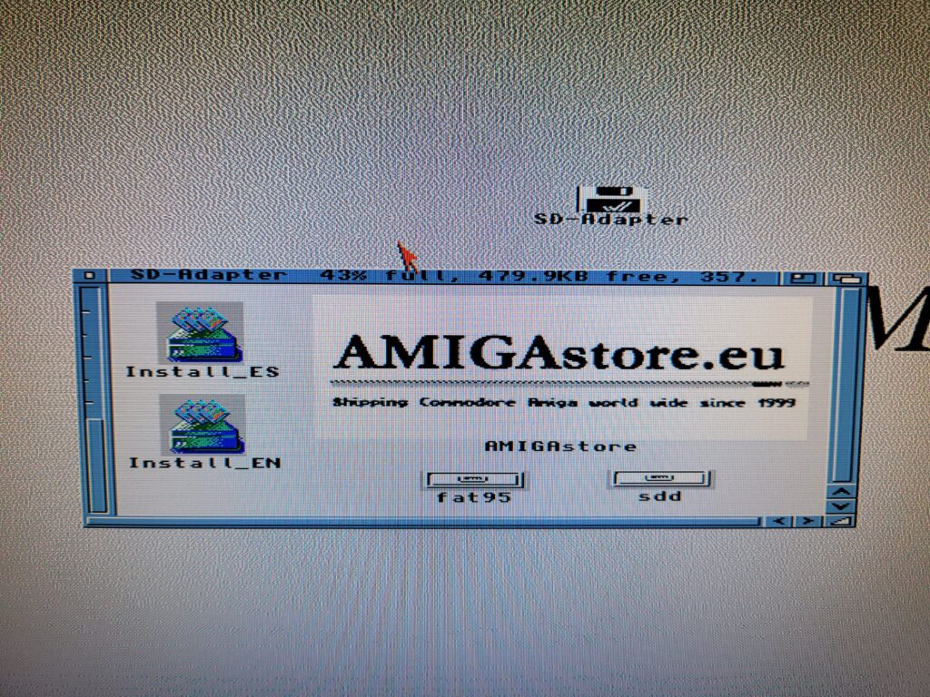
Contents of the floppy disk.


The floppy comes with a handy installer (in both English and Spanish) to copy over and configure everything necessary to use the SDBox.


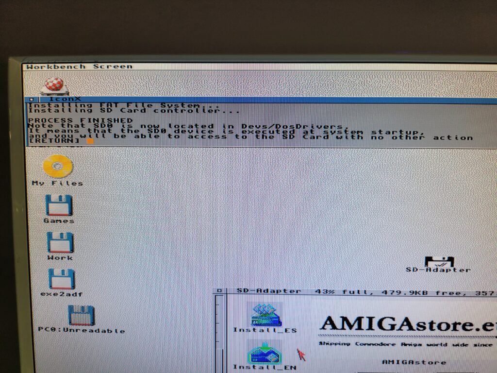
SDBox

SDBox Installer now finished.


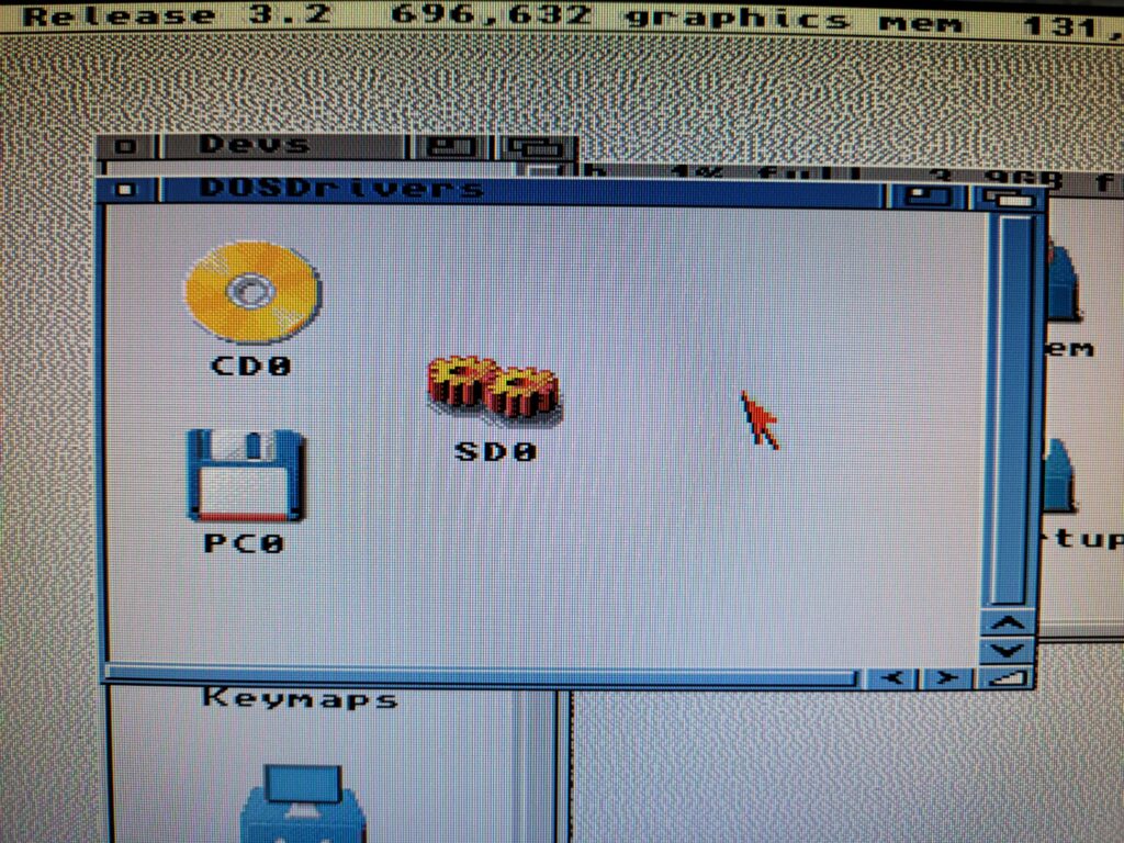
A few moments later a message appears on the screen to inform you that the install is complete and where it has put the SD0 device.


SD0 DOSDriver

This is the SD Device it installs in DEVS/DOSDrivers.


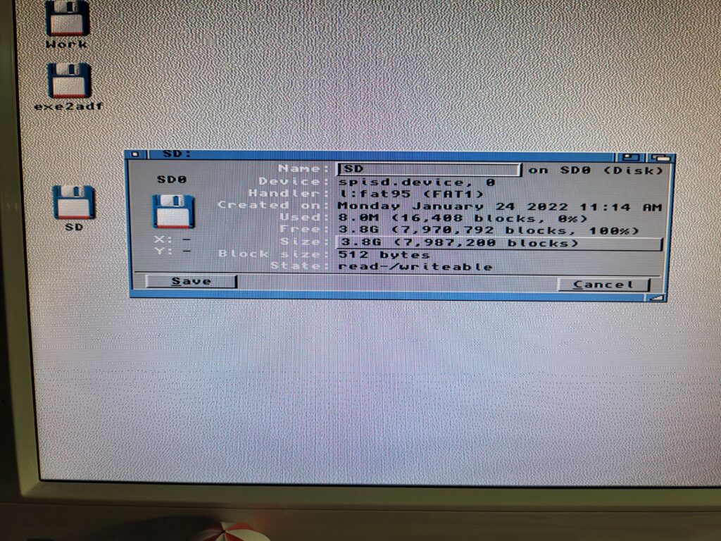
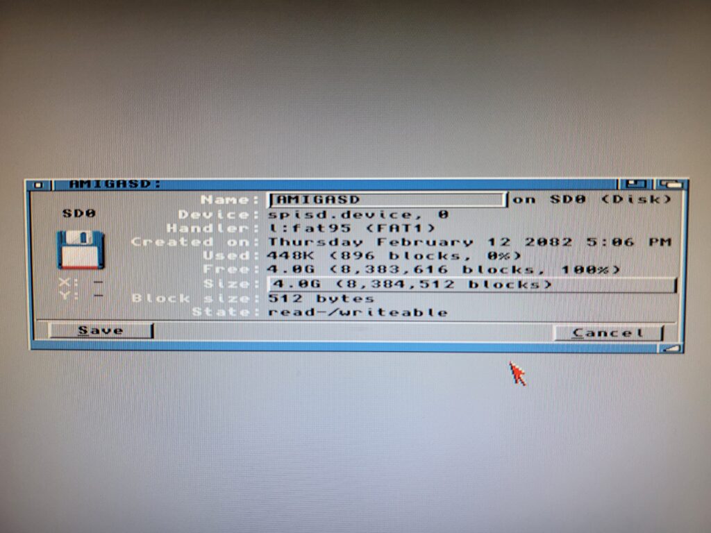
A quick reboot and my SD card was showing up on my Workbench screen, just like any other drive would. I brought up the drive info window for SD0 to confirm it was reading the card properly.


SD0 Information

Icon Information for the SD card.


SD Cards

I chose to get an SD Card with my SDBox but you can use any MicroSD card you may have lying around. The one caveat is the device is only capable of accessing 4GB partitions so if you have a bigger card you must create a 4GB (or smaller)  partition on it for it to work. There’s some info at the end of this post describing how to partition a MicroSD card in Windows if you need it.


SDBox

If you look carefully you can see the packaging has been opened already…


*Clearly AmigaStore.eu were unable to source a 4GB card for me as they actually sent me a 32GB MicroSD card that had been manually partitioned to 4GB.


Using the SDBox

In use the SDBox performed well and exactly as described. It’s not going to set any speed records but given it’s hooked up to a parallel port that’s to be expected. To give an idea of transfer times I copied an 880K ADF file from my RAM Disk to both my internal CompactFlash card and the SDBox. It took about 1 second to transfer to the CF card and 6 seconds to the SDBox. Next I tried a bigger file;  AmiSSL 4.12 which was 5.7MB. It took 6.5 seconds to transfer to my CF card and 39 seconds to complete the transfer via the SDBox. Approximately six times slower but still perfectly acceptable.


SDBox

MicroSD card being inserted in the card slot.


The SDbox doesn’t support swapping thecard whilst the Amiga is running so don’t expect it to update the contents if you do – it’ll just result in an error. It requires a full reboot to refresh the contents of the card but again this is not a great inconvenience.


Fly in the Ointment – Conflict with Indivision AGA Mk3 Flicker Fixer

On a slightly more sour note I did encounter one issue with my unit. Whenever the SDBox was accessed, whether that be reading or writing data, my screen flickered/wobbled around. You can see exactly what I’m on about in the little video clip I recorded below. After testing all sorts of things I narrowed it down to an issue with using interlaced HIGHGFX screenmodes on my Indivision AGA Mk3 flicker-fixer. Normal Amiga screenmodes, including interlaced ones, worked just fine as did non-interlaced HIGHGFX modes (all of these still going through my flicker-fixer).

Naturally Sod’s law meant that my screen was utilising ‘HIGHGFX Super-High Res Laced’ which is why I witnessed the issue from the start. It’s certainly not a deal-breaker – it’s more of an irritation than anything else (especially if you are a bit of a perfectionist). It doesn’t affect the operation of the SDBox and I can certainly live with it – just something to bear in mind for anyone with a similar setup.


I tried many things to get rid of the issue and also contacted the manufacturer of the Indivision card but so far I do not have a solution. If I ever get to the bottom of the issue I’ll update this post.


How to make a 4Gb partition on a larger SD Card.

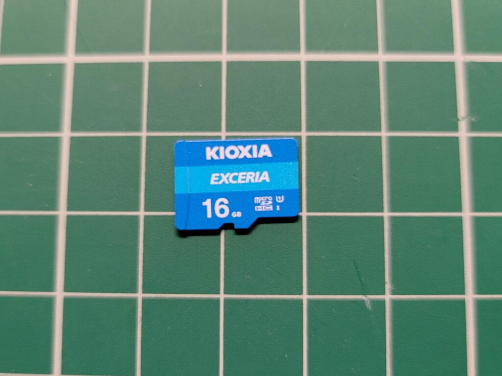
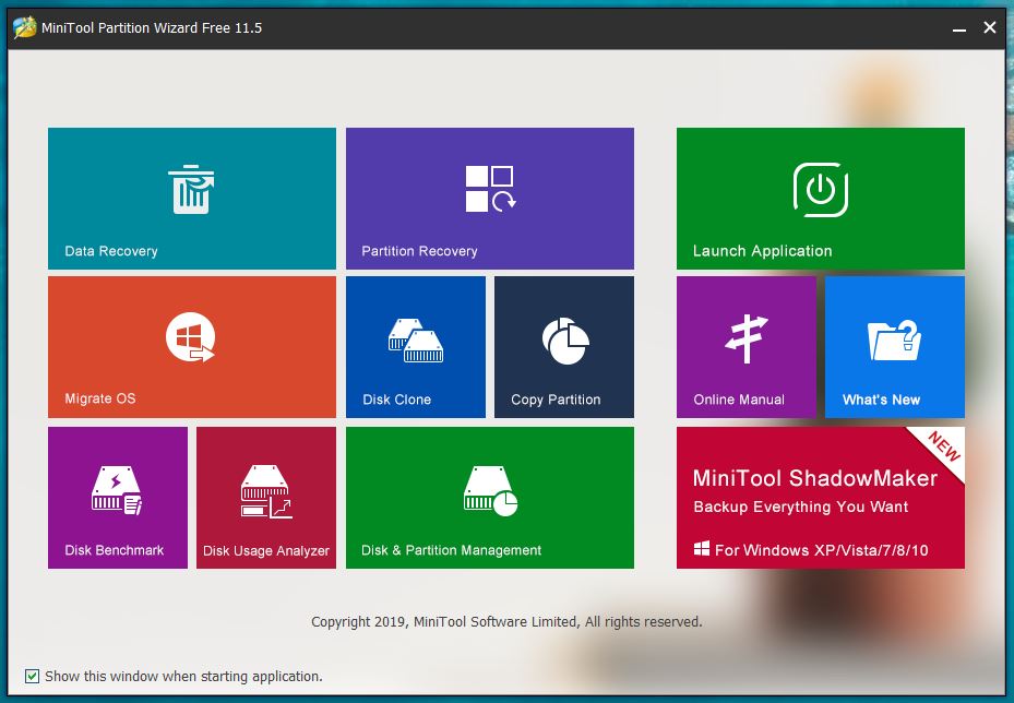
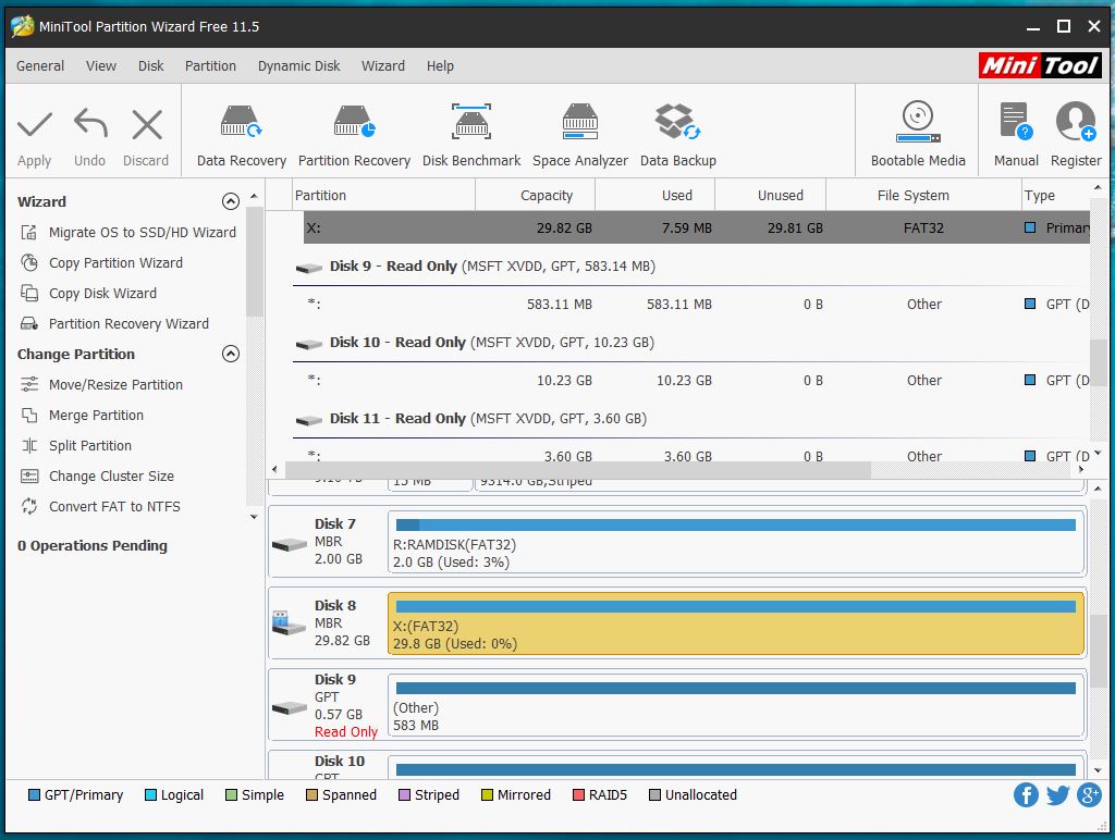
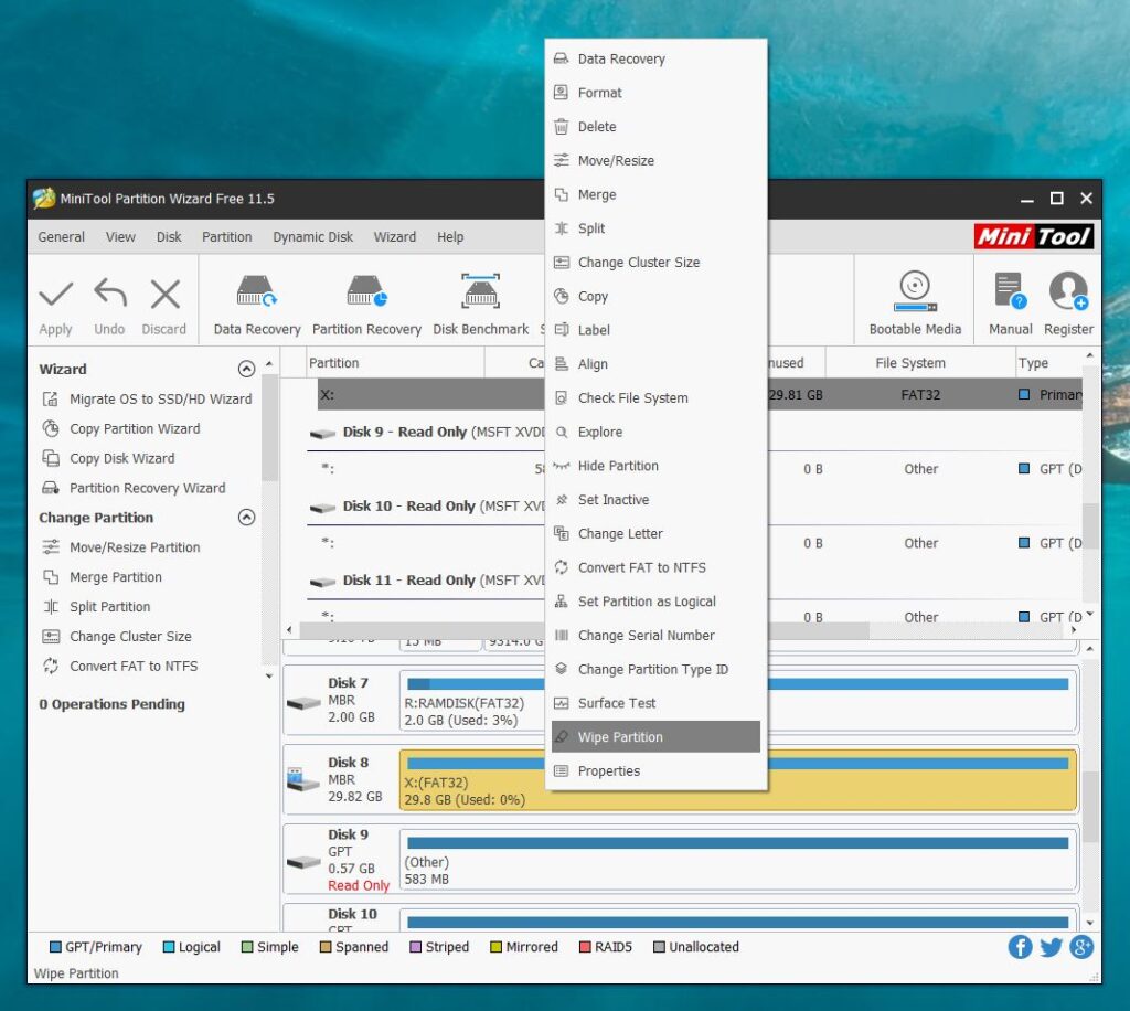
This is a pretty straightforward task to accomplish in Windows. I used a nice bit of free software called ‘MiniTool Partition Wizard‘ to do the job along with a spare 16GB MicroSD card that I had lying around.


MicroSD Card

A generic 16GB MicroSD card I used for testing.


Basically what you need to do is load up the software and then find your card in the list of drives. They normally show up slightly smaller than the stated capacity. For instance I popped in a 16GB card and it showed as 14.43GB under the list of available drives.

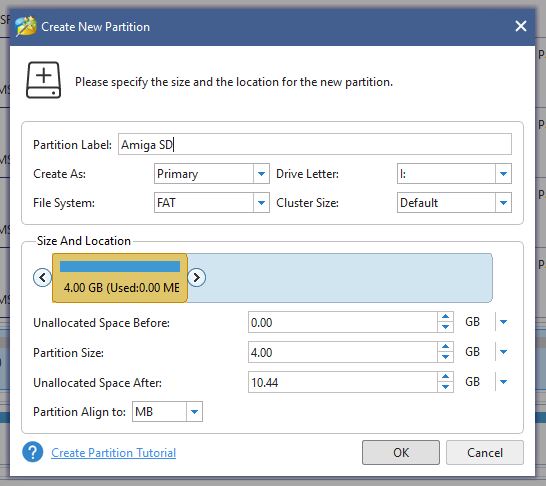
Once you’ve located it simply right-click it and select ‘Delete Volume’ then do the same again but select ‘Create’ to make a new, smaller partition. On the ‘Create New Partition’ screen select ‘FAT’ as the file system (see screenshot below) and it will shrink the size of the partition down to 4GB automatically. Give it a name (this will appear on your Amiga workbench) and then click ‘OK’ and then ‘Apply’ to make all these changes happen.


Partition Wizard

Partition Wizard – New Partition Settings


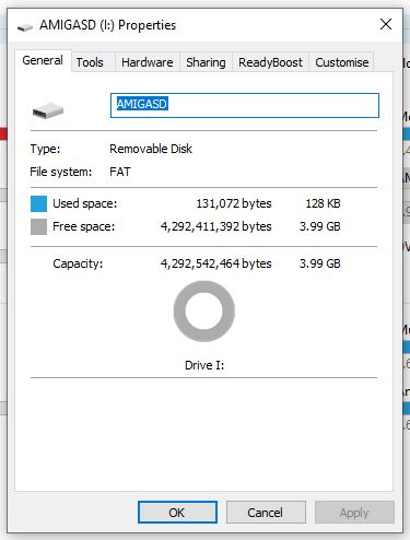
Now if you right-click the SD card and select ‘Properties’ in Windows you should get the screen below showing that the card is now recognised as being 4GB and formatted with the FAT file system.


Windows 10 Drive properties

Checking the size/format of the card in Windows.


Back over to the Amiga – pop the card into the SDBox and boot up your Amiga. You should now see the card appear on Workbench with the name you gave it in Windows. You can go to ‘Icon’ > ‘Information’ to bring up a similar properties screen to check it’s all setup correctly.


SDBox

SD Card properties displayed on Workbench


And that’s all there is to re-partitioning an SD card to work with the SDBox. Enjoy!


Installing AmigaOS3.2

Seems like it was only yesterday that AmigaOS3.1.4 was released and yet here I am with AmigaOS3.2! I actually bought this in June last year but I’ve only just got around to having a play around with it. For the time being this release is only available physically on CD which is fine by me. Hyperion say there will be a digital download version of it at some point in the future.

I will preface this post by saying that things didn’t go smoothly during my first install attempt. Hopefully someone can benefit from the issues I experienced and how I overcame them.


A closer look at the what you get…

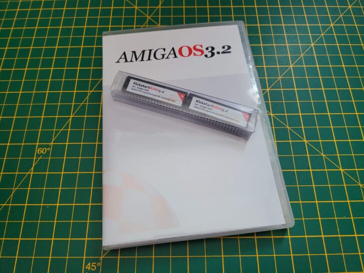
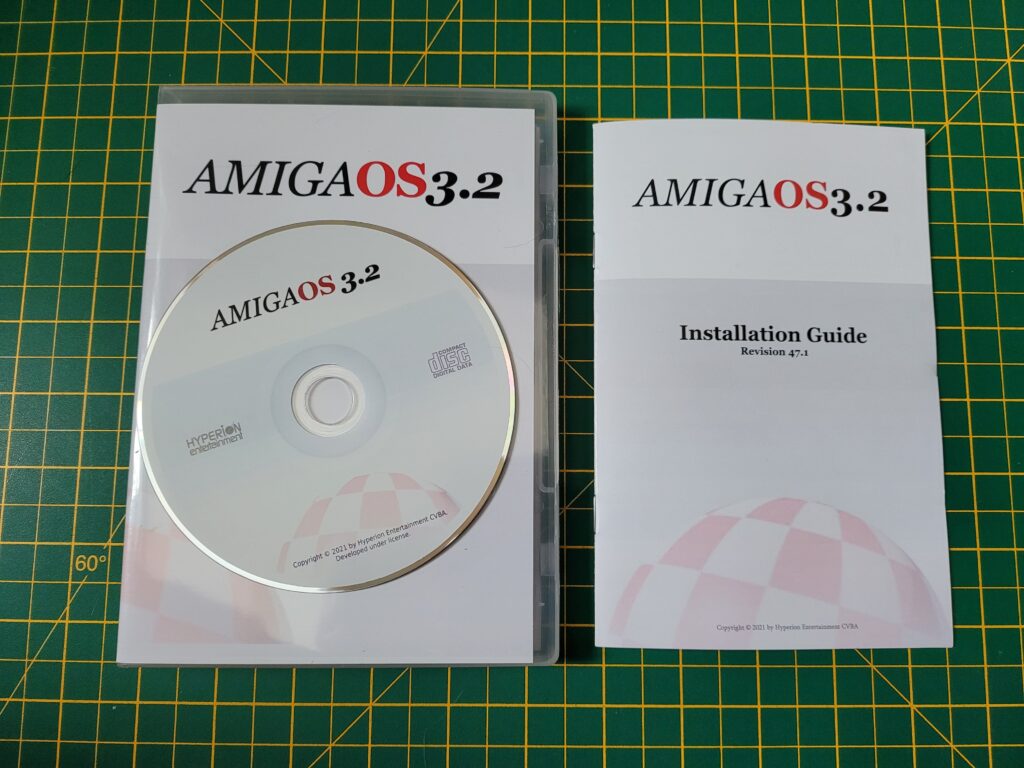
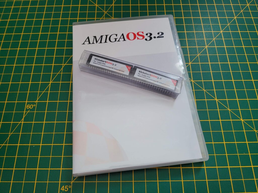
Anyway I ordered the CD along with the Kickstart ROMs for my A1200 from Amigastore.eu. I have to award top marks for presentation as the CD came in a very attractive DVD style case along with professionally printed jacket. Inside there is a 14 page manual and the silk-screen printed CD itself. Finally but by no means least there were 2 new Kickstart ROMs to replace the existing chips.


AmigaOS3.2

The AmigaOS3.2 case, CD and manual.


The serial number is on a little sticker affixed to the cellophane wrapping on the outside of the box – don’t make the mistake I did of throwing it in the bin. Luckily I realised before the bin was emptied! The code is needed to register your purchase on the Hyperion site in order to be eligible for future updates.


AmigaOS3.2

AmigaOS3.2 ROMS.


Workbench 3.2 actually spans a grand total of 35 floppy disks now which is why the decision was made to supply it on CD. Although half of those disks are either country or machine specific but it’s still a lot. The CD contains ADF images of all the discs should you wish to create your own physical versions. Likewise it contains the new ROM images so you can use them with a Vampire, map the ROMs to RAM or just use them with an emulator.


Fitting the 3.2 Kickstart ROMS


AmigaOS3.2 ROMS

Kickstart 3.2 ROMS Installed.


Naturally the first thing I did was to open up my A1200 and fit the two new ROM chips. If you are looking for detailed instructions on how to do this you can follow my detailed guide here. The important things are to get the ‘HI’ and ‘LO’ chips in the correct sockets (see photo above), that you orient them correctly (notched end of chip goes next to notched socket) and finally that you leave the last pair of pins in each socket empty as the sockets have 42 pins whereas the ROMS only have 40!


Compact Flash Card

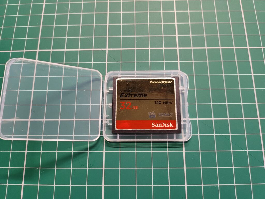
My new A1200 hard drive – a 32GB SanDisk Extreme Compact Flash card.


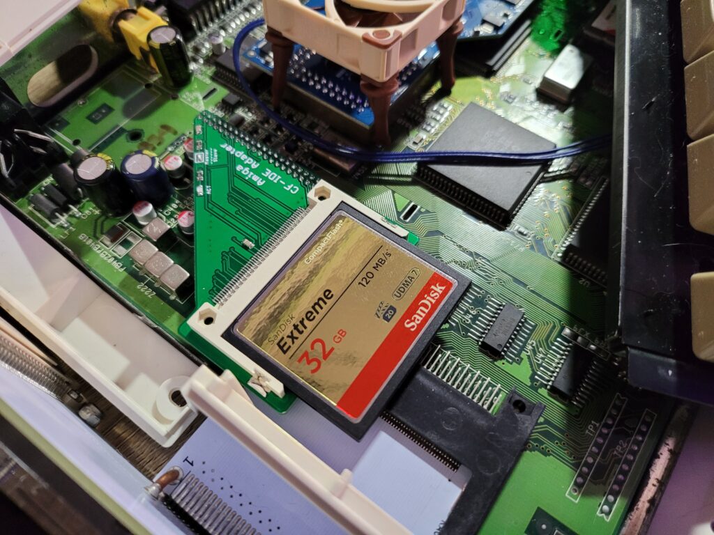
Whilst I had the case open I thought it would be a good time to install the new Compact Flash card I’d bought for the occasion. I opted to go with a nice big 32GB card this time around as it’s surprising how quickly you fill these things up without even trying. The card I bought was a SanDisk Extreme 32GB Compact Flash. I wanted something that would prove reliable and SanDisk is a brand I trust.


Compact Flash Card

32GB Card installed.


With the ROMS and new Compact Flash card installed it was time to power up my A1200 and make sure everything was working.


AmigaOS3.2

The new 3.2 ROM boot screen.


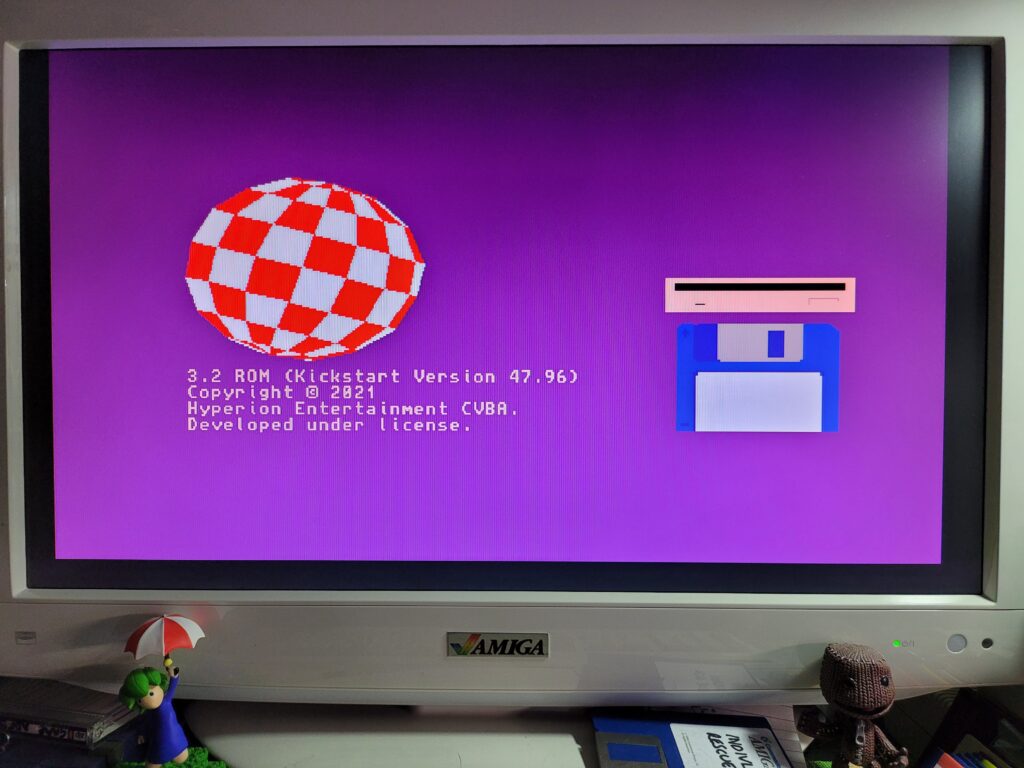
Just a few moments after turning the power back on I was greeted with a brand new boot screen. Gone was the multi-colour tick that has been there for the last thirty years – replaced by the Amiga ‘boing’ ball. Commodore’s name has also been removed and replaced with Hyperion’s. Anyway, mixed feelings aside, so far so good! Now it was time to get cracking with the Workbench install.


Prepping the disks

(The Discovery of problem no. 1)

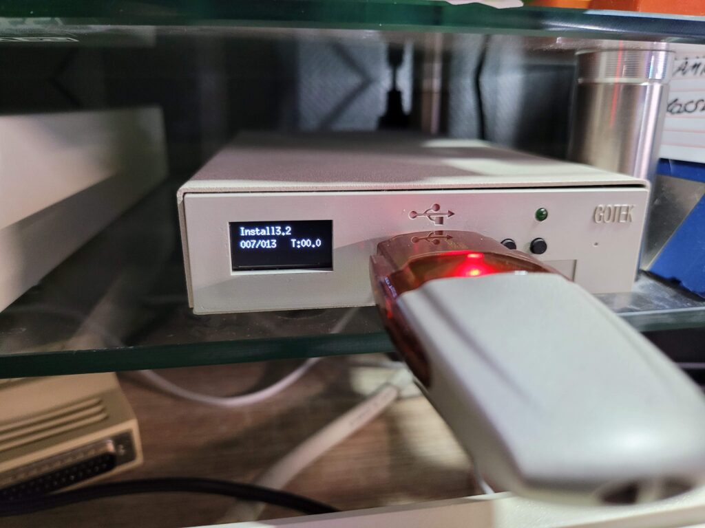
As I mentioned previously there are a whopping 35 disks in total for this install. Even after I weeded out all the language specific variations it still left 11 disks to install. Thankfully the CD contains all the disks as ADF images and if you have a Gotek drive available it’s a simple matter of copying them across to a USB flash drive and using that. This time around there are no snazzy pre-printed disk labels included either so that was another reason not to bother making physical copies of the ADF images. There are a bunch of PNG images included on the CD for you to print your own labels should you wish to though.


External Gotek Drive

The Install3.2 ADF selected ready to boot on my Gotek drive.


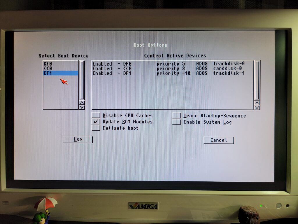
The journey starts with the ‘Install3.2’ disk so I selected that on my external Gotek and then selected DF1 as the boot device from the A1200’s Boot options screen. (Accessible by holding down both mouse buttons on bootup until the power LED flashes). If you have a Gotek configured as DF0 then you won’t need to do this.


Amiga 1200 Boot Options Screen

Amiga 1200 Boot Options Screen


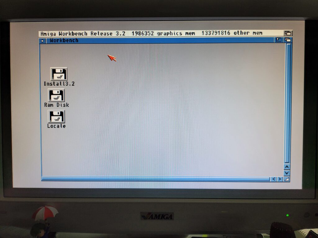
A short while later I was greeted with a basic Workbench screen and I thought I was on my way. Well you know what thought did… Everything looked OK but the mouse pointer was completely frozen – likewise the keyboard wouldn’t respond either. I tried to boot a few more times with no success. I unplugged all my peripherals, PCMICA card, audio cables, SCSI devices until all that was left was power, video and my external Gotek. Still it wouldn’t work. Maybe it didn’t like my Gotek, or the fact it was hooked up as DF1? So I created a physical Install3.2 floppy disk, disconnected my external Gotek and tried again with a real floppy in DF0. Another fail. So it wasn’t that either.


AmigaOS3.2

AmigaOS3.2 Workbench Screen (with frozen mouse).


I tried all sorts of things like re-formatting my USB flash drive and copying across the ADF’s again. I even tried a different flash drive and removing my Indivision Mk3 flicker fixer, all to no avail.

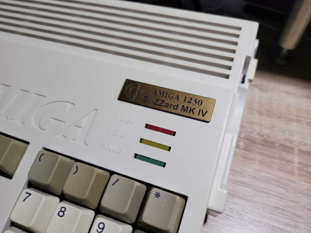
Eventually I was left with one thing I hadn’t tried – removing my Blizzard 1230 MkIV card. Luckily I remembered that the card could be disabled by holding down the ‘2’ key on boot so I gave it a try. Just like magic after doing this Workbench loaded fine and I could use my mouse and keyboard without any issues. Clearly something was up with my accelerator card.


Blizzard 1230 MKIV

Blizzard 1230 MkIV – MAPROM feature disabled with jumper removed.


More head scratching and investigations ensued until I finally discovered the source of the issue. I had the MAPROM feature enabled on my card which is supposed to speed the Amiga up by copying Kickstart into FASTRAM. However for whatever reason OS3.2 didn’t like that because from the moment I disabled it by removing the jumper (see photo above) the problem simply vanished. Happy days!


Prepping the Compact Flash Card

(The beginning of problem no. 2)


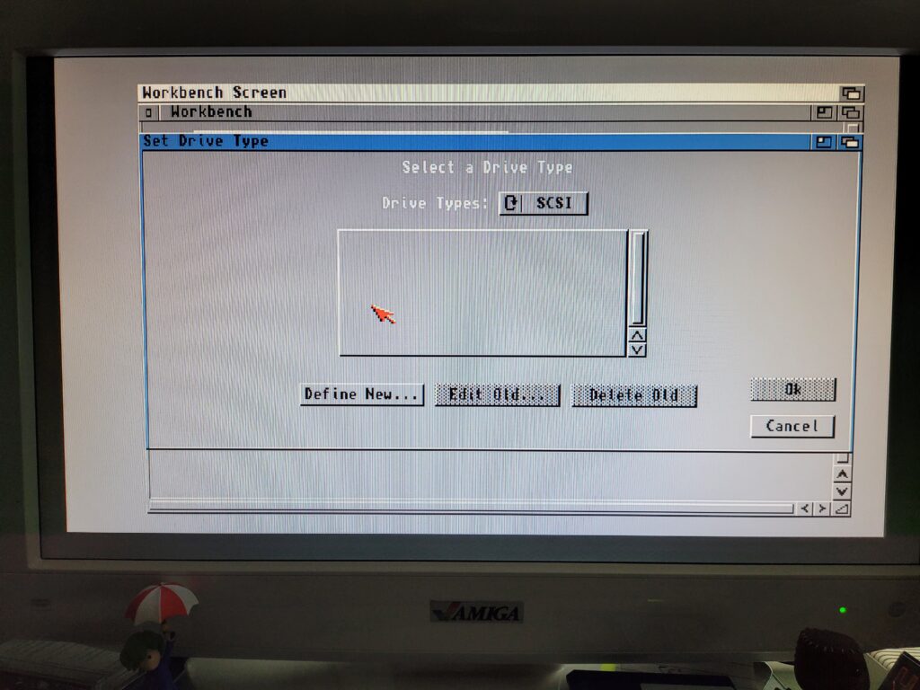
Now I had a working 3.2 Workbench it was time to Partition that nice shiny new Compact Flash card. I loaded up HDToolBox from the disk and clicked ‘Change Drive Type’.


Amiga HDToolBox

Amiga HDToolBox – Defining a New Drive


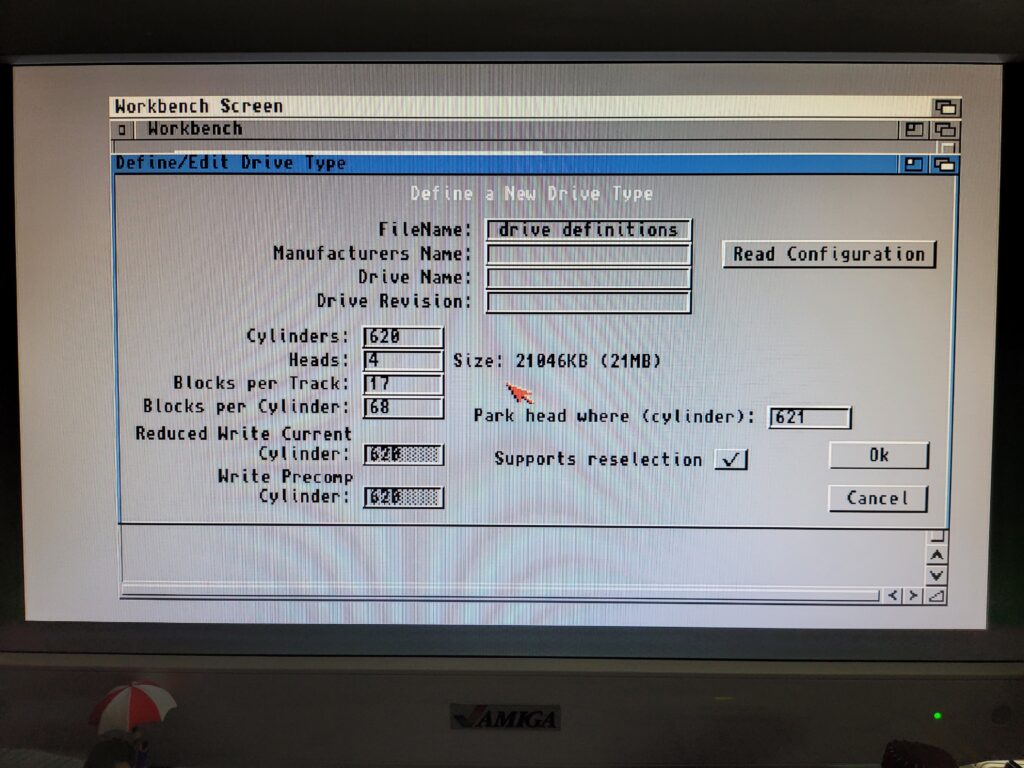
Next I clicked ‘Define New…’  which brought up the Define/Edit Drive Type window shown below.
 

Amiga HDToolBox

Drive parameters screen.


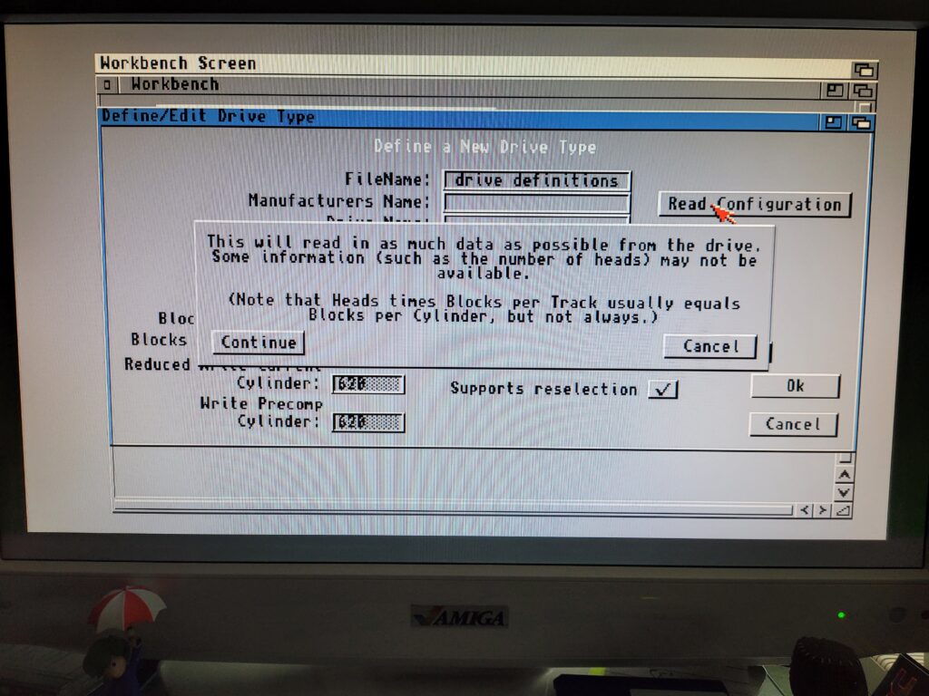
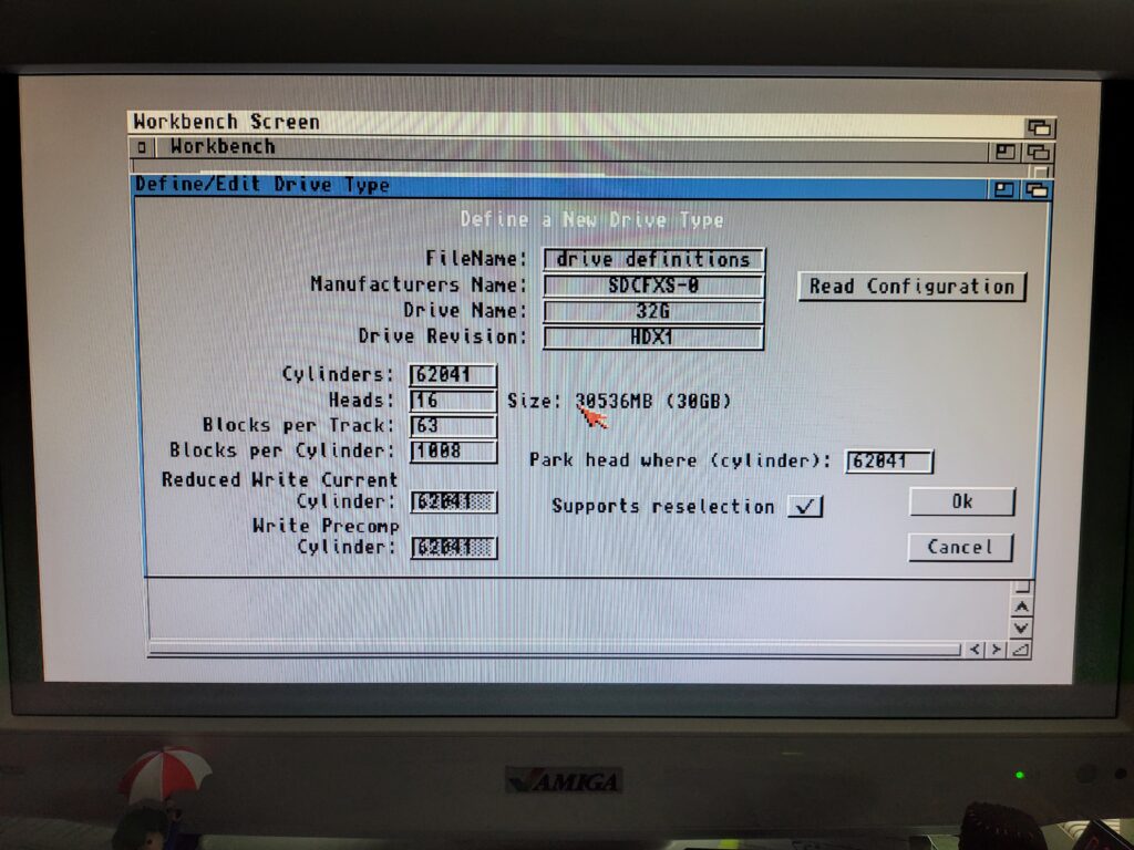
The Amiga is perfectly capable of doing all the heavy lifting here – I just needed to click on ‘Read Configuration’ to get it to extract all the necessary parameters from the card. A little info window popped up and I clicked ‘Continue’.


Amiga HDToolBox

Info Message


A second or so later and all the parameters had been pulled from the card and filled out on the screen.


Amiga HDToolBox – Defining a New Drive

All drive parameters configured.


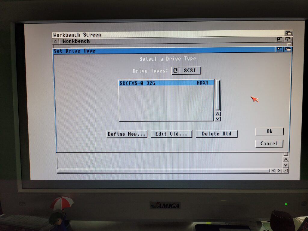
Clicking ‘OK’ brought me back to the ‘Set Drive Type’ window where I could see my newly created drive listed as ‘SDCFXS-0 32G’.


HDToolBox

Newly configured drive now listed.


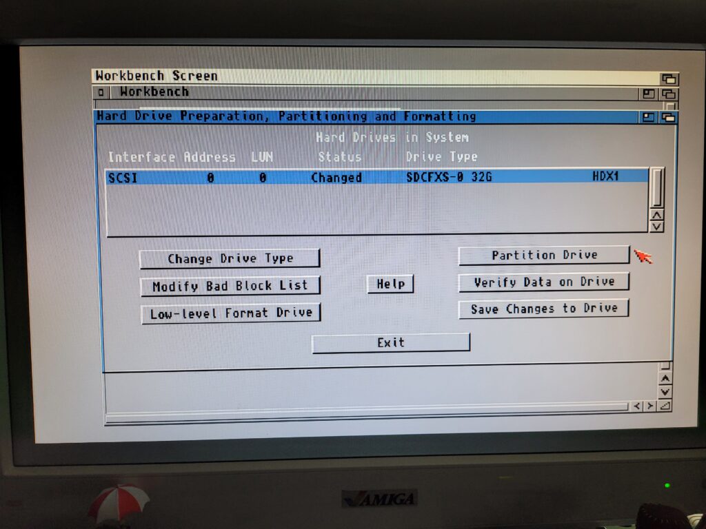
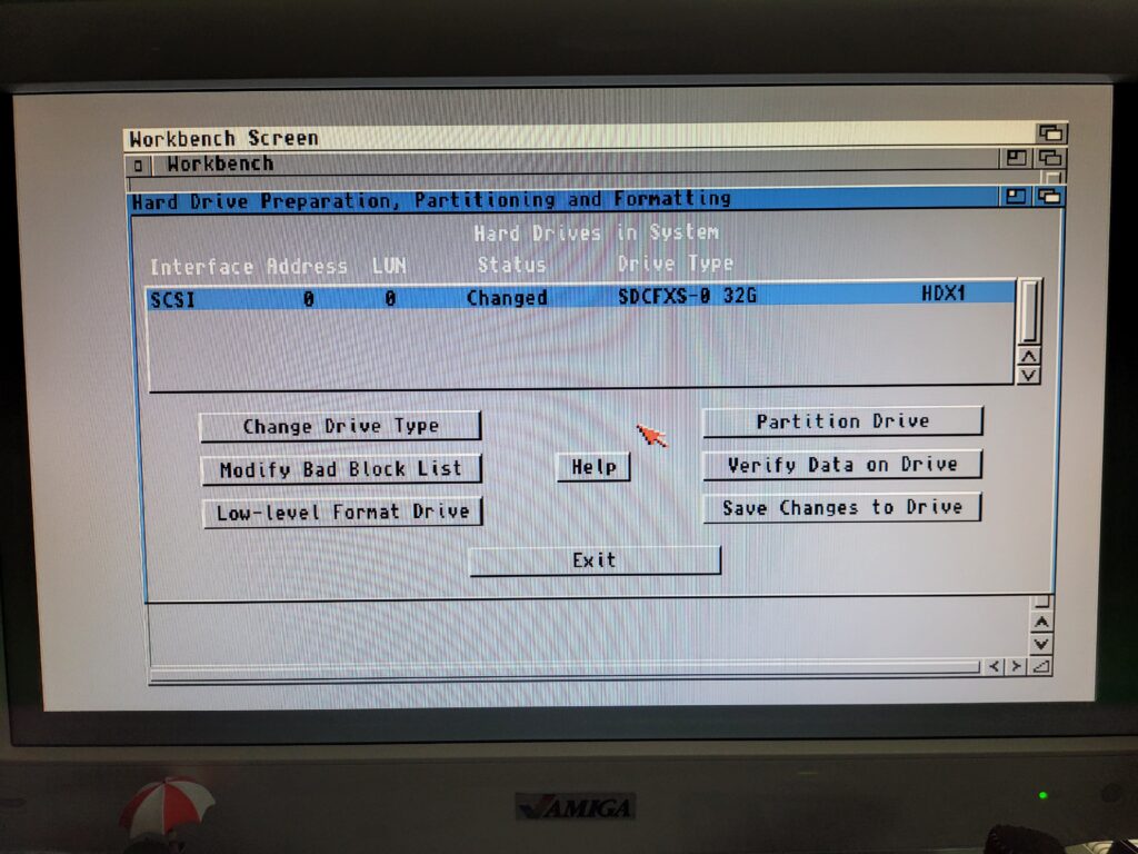
Clicking ‘OK’ again brought me back to the main HDToolBox screen, shown below.
 

Amiga HDToolBox

Don’t click SAVE just yet…


Partitioning the Card

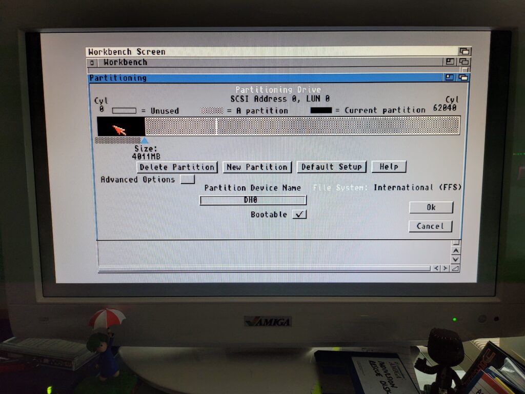
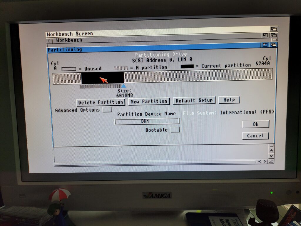
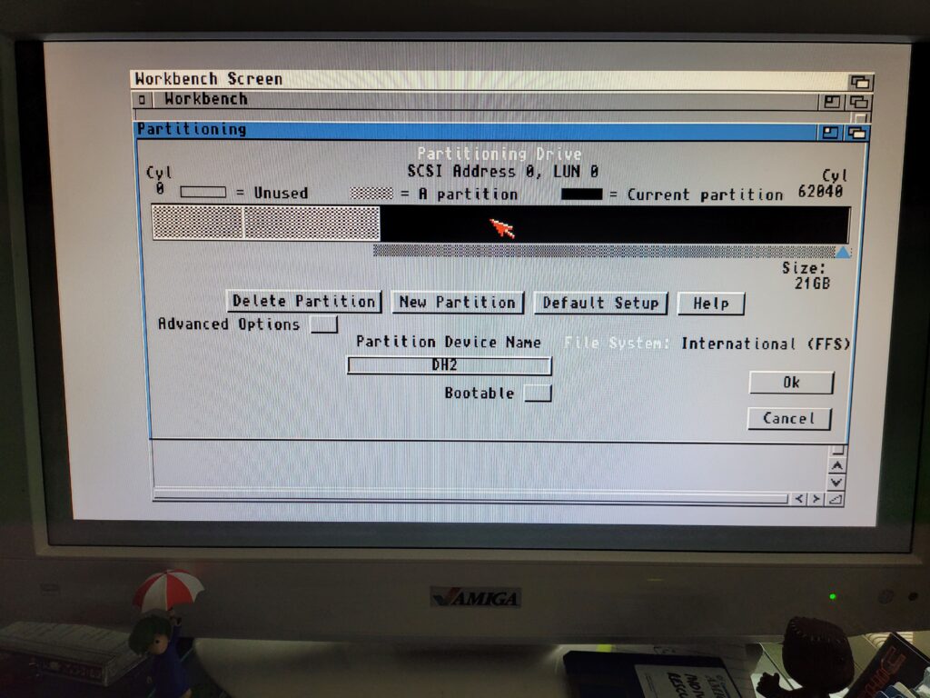
Now it was time to partition the drive by clicking on the appropriately named ‘Partition Drive’ button.


Amiga HDToolBox

Configuring my DH0 partition.


I chose to make my first partition 4GB, this would be my System/Workbench drive. To select the size I simply dragged the little triangle pointer and slid it along the bar. Annoyingly it’s still impossible to size a partition exactly so I just got it as close as I could which was 4011MB.

I called the first partition ‘DH0’ as this is the time honoured name for the Amiga’s boot drive and what most software expects to see by default. I also ticked the box to make it bootable as this is the first partition and the one the Amiga boots off.


Amiga HDToolBox

Configuring my DH1 partition.


I made the second partition 6GB (6018MB) and called it DH1. To do this I clicked ‘New partition’ and then clicked on an unused portion of the card in the visual representation on the screen.


Amiga HDToolBox

Configuring my last partition; DH2.


Finally I used all the remaining space to make one big 21GB partition and called it DH2. This will be were I install games, whether they be WHLoad or otherwise.

Once I was happy that all my partitions were sized and named exactly the way I wanted them I hit ‘OK’. (You can click each of the partitions in the bar to check their details before committing). This took me back to the main HDToolbox window shown below.
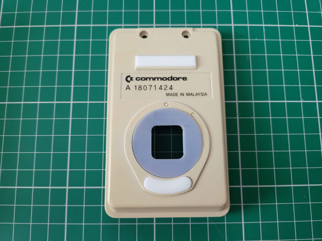
 

Amiga HDToolBox

Drive with changes waiting to be saved back to it.


To save all that configuration info and partition detail I clicked ‘Save Changes to Drive’ which flagged up a message (shown below) that a reboot was required. I then clicked continue to finish the process and write all the settings to the compact flash card.


Amiga HDToolBox

‘Reboot Required’ message.


Next I rebooted my Amiga off the Install3.2 ADF disk so I could begin formatting them. Unfortunately this was were I encountered problem number 2…


Missing DH0 partition

Spot the missing drive 🙁


There should have been three additional icons on the desktop, one for each of the partitions I had created. However for some reason DH0: was not being displayed. I tried going back through the HDToolbox configuration and making DH0 smaller and even making it the only partition on the card. Nothing worked.


Fixing the Problem

It turns out that for whatever reason, some cards are created with all the sectors on them filled with ‘1’s’ instead of ‘0’s’ and the Amiga doesn’t like that one bit.  So I had to remove the Compact Flash card from my A1200 and hook it up to my PC via a USB card reader.

I loaded up a piece of drive management software on my PC called ‘MiniTool Partition Wizard‘ (available as a free download). I then clicked on ‘Disk and Partition management’ which is the large green button near the bottom of the menu screen in the image below.
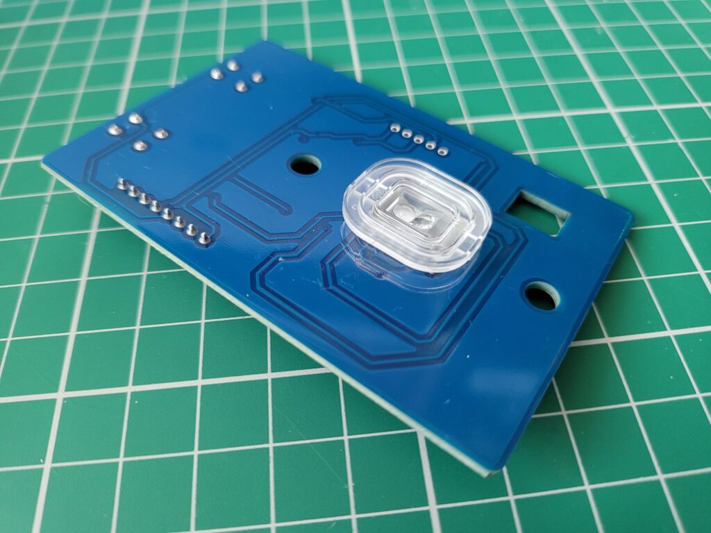
 

Mini Tool Partition Wizard

Main Menu Screen.


Next I needed to select my CF card from the list of available drives as can be seen in the image below. I knew my card was 32GB so it was pretty easy to spot – it appeared as a 29.82GB drive. It’s imperative to select the correct drive here – the consequences of picking the wrong one don’t bear thinking about!
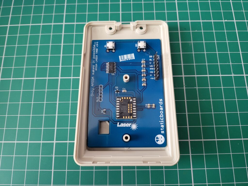
 

Mini Tool Partition Wizard

Selecting my Compact Flash card from the list of drives.


With my CF card highlighted I right clicked on it to bring up the menu and selected ‘Wipe Partition’.


Mini Tool Partition Wizard

Selecting the ‘Wipe Partition’ option.


This brought up another window along with a warning that doing this is irreversible so once again I made absolutely sure I had the correct drive selected. Definitely better to be safe than sorry when messing with partitioning software! Anyway the option to fill all sectors with zeros was already selected by default so I simply clicked ‘OK’ here.


Mini Tool Partition Wizard

Choosing how to wipe the drive.


This took me back to the main screen. Up until this point no changes had actually been made to the drive. To actually wipe the drive I needed to click ‘Apply’ in the top left hand corner. A warning then popped up about not running any other applications whilst applying the changes and then I clicked ‘Yes’.


Mini Tool Partition Wizard

Applying the pending changes to the card.


Finally the ‘Apply pending operations’ window popped up and a progress bar slowly made its way across the bottom as my card was being fill with zeros.


Mini Tool Partition Wizard

Operation Progress Window.
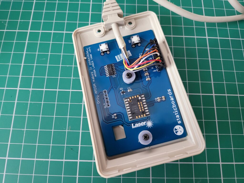
 

The whole operation took around 5 minutes or so to complete successfully at which point I was able to close down the program and remove the card.
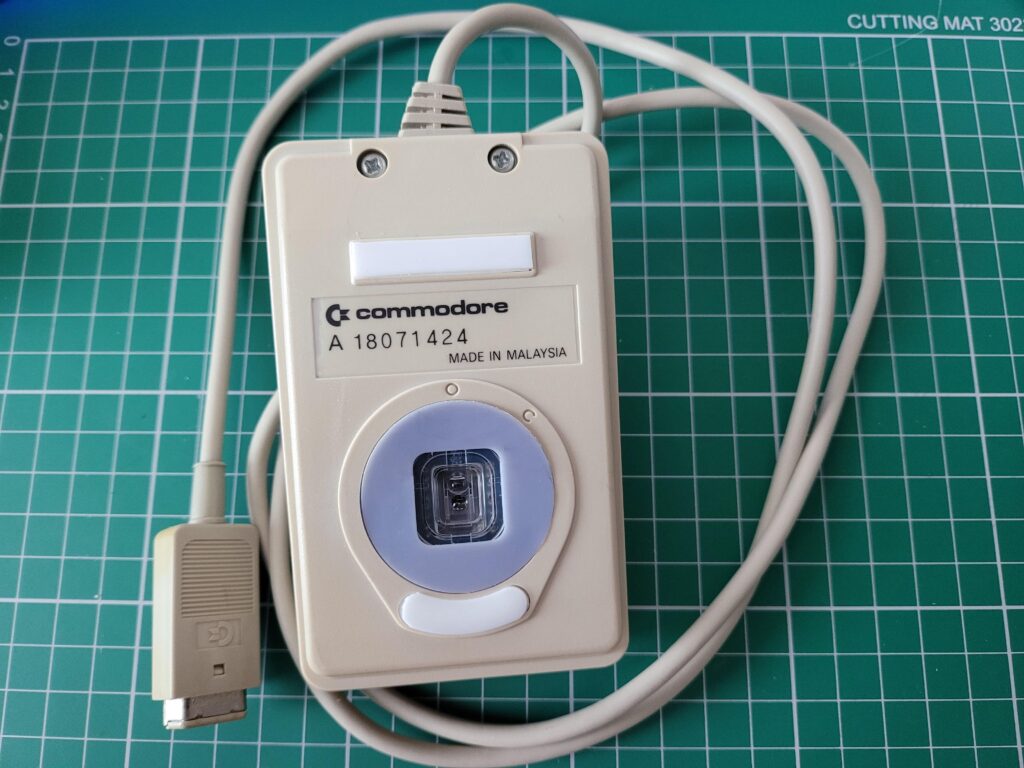
 

Mini Tool Partition Wizard

Mission Accomplished.


Back on Track.

Now that I finally had a correctly prepared Compact Flash card, I re-installed it into my A1200 and begin the entire Partitioning process again, choosing exactly the same options as before. When I rebooted at the the end of it this time I was greeted with the Workbench screen I’d been looking for. One with all 3 drive icons showing on the screen waiting to be formatted as shown below.


AmigaOS 3.2

Unformatted drive icons.


To format each drive I selected the relevant icon and then selected ‘Format disk…’ from the Icons menu.


AmigaOS 3.2

Amiga format disk window.


I named DH0 ‘Workbench’, DH1 ‘Work’ and DH2 ‘Games’. I also made sure that long file name support was ticked along with the Trashcan and Fast File System.


Amiga format disk request

Obligatory data loss warning.


I used the ‘Quick Format’ option otherwise I’d be waiting all day for the format to finish! It’s totally unnecessary for large drives anyway – the only time I ever do a full format is on floppy disks.

A couple of warning messages popped up reminding me that all data would be lost. I simply clicked ‘Format’ on both of them to get the job done.


Amiga format disk request

Last chance to bail if you’ve selected the wrong drive by mistake!


The format was almost instantaneous and once I’d done all three drives I ended up with a screen looking like the image below.


Amiga Workbench

All partitions successfully formatted.


Installing Workbench 3.2

Finally it was time to install Workbench for real. I opened the Install3.2 disk and ran the English(British) installer from within the Install folder.


AmigaOS3.2

AmigaOS3.2 English(British) Installer.


This invoked the first of many disk swaps. Thankfully I had all the ADF images on my USB flash drive so it was simply a matter of flicking through to the correct ‘disk’ and then letting the install continue.


AmigaOS3.2

Beginning the 3.2 install.


I clicked ‘Proceed’ on the first menu to appear as the other options are concerned with amendments/additions to an existing install.


AmigaOS3.2

Selecting the 3.2 Install option.


As I was doing a straightforward ‘clean install’ I left the Installation Mode set to ‘Novice User’ and then clicked ‘Proceed With Install’.


AmigaOS3.2

Selecting the Installation mode.


The next screen asked where I wanted to install OS3.2. I selected my ‘Workbench:’ partition and then clicked on Proceed.


AmigaOS3.2

Selecting where to install AmigaOS3.2.


The installer asked me which language(s) to install so being in the UK I naturally chose ‘English-British’ before hitting ‘Proceed’.


AmigaOS3.2

AmigaOS3.2 Language Selection Screen.


The next choice to present itself was whether I wanted to install GlowIcons or not. I most definitely did so I clicked on ‘Yes’.


AmigaOS3.2

GlowIcons option.


I spent the next several minutes swapping ADF disks as the installer plucked files from everywhere based on the choices I’d selected.


AmigaOS3.2

CPU Library warning.


Eventually the installation reached 100% and then popped up a message telling me I would need to install some CPU specific library files to support my 68030 CPU.


AmigaOS3.2

Installation complete.


Hitting ‘Proceed’ on that screen and then on the next concluded the first part of the install.


Booting Workbench for the First Time

A reboot was required to test out the new install so I reset my A1200 and hoped for the best…


AmigaOS3.2

Missing CPU library nag screen.


Soon I was greeted with yet another reminder that I had an 030 CPU but no library for it. I hit ‘Return’ to continue booting and a few moments later I reached the AmigaOS3.2 Workbench screen complete with backdrop and snazzy GlowIcons.


AmigaOS3.2

AmigaOS3.2 Workbench Screen.


Content with the knowledge that Workbench was working nicely it was time to fix that CPU library issue.


Installing CPU Support Libraries

Back when I installed AmigaOS3.1.4 I remember having to source the necessary MMULIBS files from Aminet. Thankfully that’s now a thing of the past as 3.2 can install the required files itself. In order to do so I needed to re-run the installer and this time select ‘Install CPU Support Libraries’ from that initial menu.


AmigaOS3.2

Installing CPU Support Libraries.


A confirmation window popped up and I simply responded with ‘Yes’ to proceed.


AmigaOS3.2

Confirming the location of my Workbench install.


The following dialogue wanted to know which model of accelerator card I had installed. As I have a Blizzard 1230 MkIV I chose ‘Phase 5’ from the list and then clicked ‘Proceed’.


AmigaOS3.2

Selecting my accelerator manufacturer.


A few moments later and the installation was complete – all I needed to do now was reboot my A1200 and make sure all the warning messages had all cleared. (They had).


AmigaOS3.2

CPU Library Installation Complete.


Configuring CD Access

There was one other quick configuration change I could make to round off my install and that was to get my CD drive working. OS3.2 includes a CD filesystem so I didn’t need to install anything extra.

The first thing to do was drag the CD0 device from STORAGE/DEVS/DOSDrivers to DEVS/DOSDrivers and bring up the Icon Information window to edit the Tooltypes. The Information window has changed a little bit under 3.2 so the Tooltypes now reside under a Tab called ‘Icon’.


AmigaOS3.2

Setting the CD ToolTypes.


There were two tooltypes I needed to alter; ‘DEVICE’ and ‘UNIT’. As I have a Blizzard SCSI card I needed to set ‘DEVICE=1230scsi.device’ as that is what my SCSI device is called. My CD drive has a SCSI ID of 3 so I set ‘UNIT=3’ and then saved my changes. As no CD device had been mounted up to this point I simply double-clicked the CD0 icon to test if the new settings worked and popped in my 3.2 CD. Happily a few moments later I could see a fancy little AmigaOS3.2 CD icon on my Workbench. Another job done.


AmigaOS3.2

Workbench 3.2 Installed and CD access working too.


With Workbench 3.2 successfully installed it was now time to get busy sorting out internet access and installing all my apps and games once more…

I’ve covered all that stuff before with 3.1.4 but if anything crops up that poses an unexpected issue I’ll add to this post.

Zzap! Amiga Micro Action – Brand new UK Amiga magazine!

2021 was a great year for Amiga magazines. Back in January there was the launch of Amiga Addict, then towards the end of the year, another brand new magazine appeared; Zzap! Amiga – Micro Action from the same guys who resurrected Zzap! 64 – Fusion Retro Books.

Zzap! Amiga

Zzap! Amiga Front Cover

The cover design adopts the familiar Zzap appearance and represents, perhaps, what we might have seen back in the late 80’s had Zzap fully transitioned over to the Amiga.

The magazine itself is A5 sized and is printed in full colour on thick glossy glossy paper, stapled at the centre. There’s a grand total of 58 pages sandwiched between the covers comprising mostly articles with a small smattering of adverts. From what I can gather Zzap! Amiga will be published 4 times a year (quarterly).

A Look Inside Issue 1

Zzap! Amiga

Zzap! Amiga Contents Page

There’s a clear emphasis on gaming here, which is to be expected considering Zzap’s heritage. This is probably why it’s only coming out quarterly too, allowing time for enough new games and news to surface. Some Zzap! regulars make an appearance including Zzap! Rrap (letters page) and The White Wizard (adventure gaming). RetroRecipes’ Chris Simpson (Perifractic) has his own section of the mag too whilst elsewhere there’s a 6 page article reminiscing about the CD32 console launch. There’s some cool featured Amiga art and a look at the success Bullfrog had with the Amiga. Of course there’s plenty of news from the Amiga gaming scene included too.

Zzap! Amiga

AMOS

AMOS Coding

Finally I have to mention I was really pleasantly surprised to see that there was an AMOS coding section near the back of the magazine. It even included a type-in listing to enter! The article also contained information on how you can legally get a free copy of AMOS to experiment with. As a big Amiga tinkerer this was definitely right up my street. I have a boxed original copy of AMOS so this is just the excuse I need to dust it off and put it to good use! I sincerely hope to see more of this sort of stuff in the future.

This slideshow requires JavaScript.

All in all this was a great read, especially if you are an Amiga gamer. It was entertaining and informative without being dry and serious. I personally would have liked to see more game reviews – hopefully issue 2 will improve things in this respect.

At £3.99 plus postage it’s a no-brainer for me and a worthy addition to my retro magazine collection. Don’t forget you can get 15% off with code ‘LYONSDENBLOG’ at the checkout!

Head on over to Fusion Retro Books to pick up your own copy. At the time of writing issue 2 is about to be published too which I’ll definitely be getting.

Cooling my A1200 – Part 2 – Adding a Fan

In Part 1 I tried some simple passive cooling techniques to increase airflow with the aim of cooling my A1200. This time around I’m going to add a hardware device to my A1200 that will monitor the internal temperatures and also add a cooling fan. Spoiler alert – this time there will be some decent results!

To be honest I probably would have stuck with the modest improvements made from the passive cooling mods had it not been for the extra heat generated by fitting my Indivision AGA Mk3 Flicker-Fixer. When I began to see artefacts on the screen caused by the Lisa chip working overtime and heating up I knew it was time to step up my game.

AmigaKit Real Time Clock and Sensors Module

I discovered this Sensors Module quite by accident whilst browsing the AmigaKit website. It’s a little battery-backed clock module that incorporates an ambient temp sensor on the board and can be expanded to include a second temperature sensor probe by means of a small 3-pin connector.


AmigaKit Real Time Clock and Sensors Module

AmigaKit Real Time Clock and Sensors Module with £1 coin for scale.

In addition to monitoring temperatures and providing a clock function this module also incorporates a 5V sensor that can monitor the stability of the A1200’s 5v power rail.


Top of AmigaKit Real Time Clock and Sensors Module showing the remote sensor connector.


Handily it is also able to monitor the power level of its own battery for the clock module.


Remote sensor probe.


The temperature probe is sold separately and is available here. It simply attaches to the 3-pin socket on the sensor module and allows for monitoring a second location within the Amiga or specific chip depending on where you place the end of the probe.


AmigaKit Real Time Clock and Sensors Module with the optional probe fitted to clock port and probe placed over the Lisa chip/Indivision.

The sensor module attaches to the clock port next to the Kickstart ROMs’ and the probe can be placed anywhere inside the case. As I was interested in the temperature of the Lisa chip and the Indivision I placed the end of the probe there.

Software

Now having the hardware is all well and good, but how do you actually get the readings from it? Well AmigaKit supply a custom program for the Amiga that you install to take care of this. It actually comes as two separate programs, the first of which is called ‘AK_Sensors and is installed into the WBStartup folder. This program runs as a commodity and polls the sensors every 30 seconds and stores the values as environment variables in ENV. The polling interval is infinitely adjustable from between 1 second and 24 hours by means of a tooltype setting.


AmigaKit Real Time Clock and Sensors Module

AmigaKit Real Time Clock and Sensors Module Software.


The second program, AK_Sensors_Display is what actually displays the readings on the Amiga’s workbench. This can be installed anywhere you like but if you want it to be displayed all the time then place it in WBStartup.

With the hardware and software installed it was time to get some readings. To do this I left my A1200 running for a couple of hours and then checked the readings.


Amigakit sensor

Sensor readings after 2 hours.


After 2 hours the internal temperature of my A1200’s case measured 50.9C whilst the probe placed on the Indivision/Lisa chip was reading 54.2C.

Now I had accurate and easily accessible readings it was time to do something to improve them!


Active Cooling Time

After doing some research into quiet fans I settled on this one: a ‘Noctua NF-A4x10 FLX, Premium Quiet Fan, 3-Pin (40x10mm).  


Amiga Active Cooling Fan

Just a fan, ma’am.


It got many glowing reviews online and I was especially encouraged by seeing comments like ‘whisper quiet’ and ‘near silent’.


Amiga Active Cooling Fan

I’ve never seen such elaborate packaging for a simple fan before!


As small cooling fans go this was probably quite expensive but my Amiga is definitely worth it so I ordered one from Amazon. I was very impressed when I received it as it’s in a really cool presentation box complete with a plethora of cables and accessory doodads.


Amiga Active Cooling Fan

Plenty of extras come supplied in the box.


As the fan is 12V I intended to power it from the Amiga’s 12V floppy drive supply so I also ordered a floppy drive Y-splitter power cable from AmigaKit to take care of this.


Amiga Active Cooling Fan

AmigaKit floppy power splitter Y cable.


This will allow me to tap into the 12V supply neatly and safely and as it replaces the original floppy cable rather than modifying it, is completely reversible too.


Amiga Active Cooling Fan

AmigaKit floppy power splitter closer look.


Fitting the Fan

The fan came with a whole host of different mounting options but I chose to use the silicone anti-vibration mounts. I fitted them through the 4 mounting holes in the fan and then cut the excess lengths off flush with the fan.


Amiga Active Cooling Fan

Silicone anti-vibration mounts fitted and trimmed to size.


These mounts appeared to be sized perfectly to mount the fan above the Indivision board and by positioning them around it would also keep the fan anchored in place.


Amiga Active Cooling Fan

Fan fitted neatly over the Indivision. The back 2 legs are splayed slightly which actually helps to keep it held in place.


With the method of fitting the fan sorted I then turned my attention to wiring it up. I snipped off the power connector on one side of the Y splitter cable so I was left with 4 wire strands. Then I snipped off one of the black (ground) wires and the red (5V) wire from the same side. This left me with the Yellow (12V) and remaining black (ground) to power the fan. I then replaced the floppy power cable with the modified Y splitter version.


Amiga Active Cooling Fan

Tapped into the 12V and Ground wires using skotchlock connectors.


Next I used the ‘OmniJoin’ cable (supplied) together with a couple of Skotchlock connectors (also supplied) to attach the fan to the two wires from the floppy drive Y connector.


Amiga Active Cooling Fan

Wiring tucked away neatly.


The black wire of the floppy cable connected to the corresponding black wire of the OmniJoin cable. However the yellow wire from the floppy cable needed connecting to the red wire of the OmniJoin cable. The fan does actually have a yellow cable of its own but this for sensing the fan speed and not required for our Amiga project.


Amiga Active Cooling Fan

Everything fitted ready to put it all back together.


I also made sure that the red/black wires of the OmniJoin cable correctly lined up with that of the fan when it was plugged in. You can just make out the colours of the fan wires going into the fan plug in the image below.


Amiga Active Cooling Fan

Making sure that the red and black wires match up on the two connectors.


With everything in place I gave it a quick power-on to ensure the fan was working. It whirred into life immediately so I re-fitted the keyboard to check the clearance and was happy to find there was just enough to not cause any issues. If there had been I could have just trimmed a little off the mounts to shorten them.


Amiga cooling fan

Just enough clearance between the keyboard and the top of the fan.


Finally I replaced the lid and carefully inserted the screws from underneath. If I flipped it over like I normally would then the fan would become dislodged as it’s not actually fastened down.


Will you Start the Fans Please

With everything back together and the cooling fan installed in my Amiga I powered it back on to assess the fan noise. I was pleasantly surprised to discover that it was very quiet indeed, just as advertised. It’s not silent and I can hear it but it’s just a soft whirring sound and not at all distracting even in a quiet room.

Of course being quiet is one thing but was it actually going to cool my Amiga down? I left my A1200 powered on for a few hours just like I’d done previously without a fan installed to find out. Two hours later I checked the readings and you can see them in the image below.


AmigaKit Sensor

Sensor readings after 2 hours with fan installed.


As a reminder, without the fan, after two hours the internal Case temperature was reading 50.9C and the Indivision was at 54.2C.

With the fan installed and after running for the same length of time the internal case temperature was now 6C cooler at 44.9C whilst the Indivision had dropped an impressive 11.3C to 42.9C.  The case also felt noticeably cooler with no prominent ‘hotspots’ like before.

Needless to say I am delighted with this modification. The whole thing was non-destructive and completely reversible and it only cost around £20 all-in. As the 12V floppy power feed is for the drive motor it’s an ideal power source as most of the time it’s idle anyway. Even so I’ve used floppies pretty extensively since fitting the fan and have had no issues at all even then. Of course your mileage may vary and if you have a borderline PSU then this might just tip the balance.


Just one more thing…

Throughout this whole project one thing had been bugging me – the Compact Flash IDE adaptor and its ‘flappy’ ribbon cable. When it wasn’t getting in the way of the fan it was stopping the top of the case from fitting back on properly. It had to go!


90 Degree CF-IDE Adapter.


I had a look around and discovered a nifty looking right-angled 90 degree CF-IDE adapter on eBay so I bought one immediately.


90 Degree CF-IDE Adapter.


Fitting it was a breeze and the card now sits neatly just above the PCMCIA socket and everything looks neat and tidy once more, just how I like it.


Neat and tidy again.

Indivision AGA Mk3 Flicker-Fixer

I’ve wanted an Indivision AGA Mk3 flicker-fixer for quite some time but have been stymied by a combination of Brexit and Covid-19. Individual Computers actually halted all shipments to the UK in December 2020 as a direct result of this situation. Undeterred, I kept checking the situation periodically to see if it had changed. Sure enough, towards the end of April I saw the news I’d been waiting for. Shipments to the UK were back on! I quickly ordered myself one and waited patiently for it to arrive.

Happily I didn’t need to wait for long as it arrived within a week and with no extra fees to pay too! Needless to say it was taken straight into my man cave to open it up!


Unboxing


Indivision AGA Mk3

This is the box it comes supplied in.


Inside the attractive cardboard box was the flicker-fixer, a single mounting screw and an instruction sheet.


Indivision AGA Mk3

Contents of the box.


The included instruction sheet wasn’t brilliant if I’m honest as the print quality was very poor. Thankfully there’s a much better version online on the icomp.de Wiki here.


Indivision AGA Mk3

The Indivision AGA Mk3 in all its glory.


The Indivision AGA Mk3 consists of three main components. The largest circuit board is the actual flicker-fixer whilst a smaller board handles keyboard signals. Finally there is a VGA/HDMI connector attached by means of a ribbon cable to the main board.


Indivision AGA Mk3

The main flicker-fixer board.


The main flicker-fixer board (above) features a large socket which allows it to connect to the Amiga 1200’s Lisa graphics chip and perform it’s scan-doubling and flicker-fixing duties.


Indivision AGA Mk3

The U7 CIA chip interface.


The smallest board has a socket that connects to the U7 CIA chip. This allows it to check for a specific combination of key presses to bring up the ‘Live Edit mode’.


Indivision AGA Mk3

The double sided video connector board.


The Indivision AGA Mk3 supports both VGA and HDMI monitors by means of a board that incorporates both types of connectors on it.


Indivision AGA Mk3

VGA Connection.


You simply install the board with your preferred connection method facing outwards. It’s intended to fit in the A1200’s expansion port and a single screw is supplied to securely attach it to the bottom of the case.


Indivision AGA Mk3

HDMI Connection.


Preparation

The very first job was to remove the A1200’s metal RF shield which was blocking access to the areas of the mainboard I needed to get to. This necessitated removing the floppy drive, a couple of screws along the front edge of the board and bending up several little tabs all around the shield. Once I’d done this I was able to lift away the shield with only a little bit of leverage from a screwdriver required along the back edge. This resistance was most likely the result of the small amount of corrosion present on my RF shield.


Amiga 1200 RF Shield

RF Shield On.


With the RF shield removed I now had unrestricted access to the entire A1200 motherboard. I don’t think I will be putting it back on any time soon as it would need modifying to fit around the Indivision. Besides, with it permanently off I have easy access to the board for future projects.


Amiga 1200 motherboard.

RF Shield off. Motherboard revision information viewable. (Rev. 1.D.4)


Board Revision

Interestingly, with the shield off I could now see the information printed on my A1200’s motherboard. It was identified as being a Revision 1D4 board. These boards are also recognisable by the fact that the mouse port isn’t actually part of the board itself but rather connected to it via a ribbon cable. Earlier revisions had the mouse port on the board itself whilst the later R2 motherboard had the mouse port on a separate little board. My 1D board also has a half-width clock port header whereas earlier boards had full length ones.


Indivision AGA Mk3

The chips outlined in yellow show where the Indivision AGA Mk3 connects to the A1200 motherboard. The larger chip is Lisa and the smaller one the U7 CIA.


Installation

Fitting the main Indivision AGA Mk3 board was fairly straightforward as no tools or clips are required. The board employs an empty socket to latch onto the Lisa chip and grip it tightly. I made absolutely sure that it was aligned correctly and then carefully pressed it into place. The instructions make it very clear that it must ‘click’ into place to be properly installed and this does require quite a scary amount of pressure to be applied. After a few moments of applying steadily increasing force to the board it did eventually snap into place with a very satisfying ‘click’. I then made a visual check all around the Lisa chip to ensure it was seated completely flat.


Indivision AGA Mk3

The Indivision AGA Mk3 successfully mated to the Lisa chip…


The next stage was to fit the U7 CIA chip connector.  I had to consult the wiki to check the location and orientation of this as the instruction sheet was so murky I couldn’t make it out. It’s quite a tight fit next to the keyboard connector but at least it didn’t require as much pressure this time.


Indivision AGA Mk3

…and the U7 CIA chip.


The final installation step was to find a home for the HDMI/VGA sockets. In an ideal world the connectors would fit into the expansion bay beneath the floppy drive but that space is already occupied by my Blizzard SCSI port. My A1200 has had the RF Modulator removed and I had hoped it would fit there but unfortunately there was insufficient width to accommodate it so this location was out  too.


Indivision AGA Mk3

My placement of the HDMI/VGA connector between the trapdoor expansion slot and the floppy disk drive.


After trying a few places I settled for a position between the floppy drive and the trapdoor expansion bay. It fits there nicely and allowed me to run the HDMI cable under the case and up through the trapdoor. I applied several strips of insulating tape to the base of the HDMI/VGA board to prevent any possible short-circuits. It’s not the perfect solution as I’m unable to unplug it without removing the case but it’s an acceptable compromise. I made sure to use a nice thin, flexible HDMI cable which made routing it through the trapdoor and underneath very straightforward.


Indivision AGA Mk3

This is the screen overlay that provides info about the current screen mode.


It was finally time for the moment of truth – the big switch on. After powering on my A1200 I waited patiently and after a few tense moments an Individual Computers overlay appeared in the corner of the screen. Having seen proof of life – it was now time to see what it could do!


Configuring a 16:9 Workbench Screen

I downloaded the HighGFX screenmodes off Aminet and also the Indivision config tool off the icomp.de website and set to work creating the perfect Workbench screen…


Indivision AGA Mk3

Adjusting the screen settings.


There are two sides to this – the Amiga screenmode and the Indivision mode. The way it works is the Indivision detects the screenmode the Amiga is using and then maps it to one of it’s built-in preset (monitor friendly) output modes. With the Indivision Config tool you are able to create your own modes too and there’s a plethora of settings to tweak if you have the patience. Thankfully the preset modes cover most of the common Amiga screenmodes so most people will probably be fine with what’s supplied ‘out of the box’.

Back to my perfect Workbench screen… I spent the next few hours fiddling about trying to get a proper 16:9 mode working on my HDTV with a native resolution of 1366×768. I was trying to get the HD720 HighGFX mode working which should have given a perfect 1:1 pixel aspect whilst also utilising the entire screen width. However I just couldn’t get any combination of Amiga screen mode and Indivision settings to display correctly, even after painstakingly tweaking the 1280×720 preset to perfectly fill my monitor screen.


Indivision AGA Mk3

My widescreen Amiga display using just the output of the Lisa chip, no RTG required!


In the end I settled on the HighGFX Super High Res Laced 1024 x 768 mode which worked perfectly as the Indivision matched it to an existing VESA 1024×768 mode. The image fills my entire screen and is super crisp and vibrant thanks to the all-digital nature of the HDMI output. The only slight niggle is the image is very slightly stretched horizontally. This is because although the Amiga screenmode has a 1:1 pixel ratio – it’s intended to be used on a 4:3 monitor screen, not 16:9. However it’s by no means a deal-breaker and having such a massive (by stock Amiga standards) screen makes Workbench even more pleasurable to use.


Amiga screenmode preferences

Screenmode preferences showing HighGFX screen mode selected.


One day I will have another go at creating a perfect 1:1 16:9 Workbench screen but for the time being I’m satisfied with what I have now.


Indivision AGA Mk3

Indivision overlay showing both the detected Amiga screenmode and the preset mode being used to display it.


Configuration Tool

The card has its own dedicated configuration tool that you install to your Preferences folder. It allows you to create, test and tweak an almost limitless array of screenmodes, whether they be for productivity apps or PAL/NTSC games. Hidden away in the advanced section there is also an option to route audio through the HDMI cable too if you have a TV/Monitor that has speakers. I have my sound routed through a Bose Soundlink Mini as my TV speakers are pretty wimpy but this would be a great option otherwise.


Indivision AGA Mk3

Indivision AGA Mk3 Configuration Tool.


Glitch in the Matrix

I did notice an issue after using the Indivision card for a few hours – I was seeing some random flickering pixels on my screen. It got worse as time went on, and my Amiga was getting very warm too, much warmer than it would normally do. Naturally I immediately thought there was a fault with the card but after I RTFM again I discovered that this is actually quite a common issue and isn’t a fault at all. I was able to eradicate it completely by using the config tool and enabling ‘CCKLine Capacitance’ from the advanced options. I’m not going to pretend I understand what this does but it definitely fixed the issue for me. There are other settings that can fix other glitches too but thankfully this is the only issue I came across. I am still not entirely happy about the extra heat it generates but I intend to sort that with a few upgrades very soon.


Indivision AGA Mk3

My Indivision card stopped being recognised!


Reports of my death have been greatly exaggerated

The Indivision card also tried to fake its own death at one point. I’m not entirely sure what happened but I had been messing around with the ‘live edit’ feature and the next thing I knew the Indi was no longer being detected. To make matters worse when I rebooted my Amiga it was using a screen mode that my monitor could not display so I couldn’t even see the screen. I tried removing the card and re-seating it but it still refused to work.

Now by this point I honestly thought it was dead and I’d have to return it. Then I remembered about the Rescue Disk recommendation I’d seen on the website. Amazingly I had read this and actually bothered to create one! I popped it in the drive, rebooted and after what felt like an eternity my Amiga booted up again and the card came back to life. I’ve never been so glad that I bothered to follow a set of instructions for once! I’m guessing I corrupted it’s firmware somehow and the repair disk re-flashed it but the main thing was my card wasn’t broken.

Live Edit Mode

Speaking of the ‘Live Edit Mode’ this is a utility that can be displayed at any time (even during a game) by holding down Left Shift, CTRL and Tilde. The fact this can be invoked at any time is thanks to that connection with the U7 CIA chip which allows it to detect the key-presses.


Indivision AGA Mk3

Indivision AGA Mk3 Live Edit Mode.


Whilst this mode is active you can move the on-screen image around your monitor with the mouse. You can also resize it whilst holding down the left mouse button in both the vertical and horizontal directions. This is a really useful feature and allows you to deal with any screenmodes that don’t have presets in the Indivision’s configuration. Once you’re happy with the screen layout simply press Tilde to exit Live Edit mode and ‘keep’ your adjustments. Whilst these ‘Live’ changes are not permanent by default (they are lost when power-cycling) there is an option to store them later in the config tools should you wish to.


This slideshow requires JavaScript.


In the example above I used the Live Edit mode to force Cannon Fodder to fill the screen of my 16:9 TV and remove all the black borders.


Do Adjust your TV Set

Many interesting settings are hidden away in the ‘Test/Adjust’ section, not least of which is the ‘Darken’ option. This basically emulates the scanlines of a CRT monitor on your modern flat screen monitor. Settings range from 6% to 75% depending on how strong you want the effect. It only works on Double-scan modes and defaults to being switched off. There are also several settings for the On-Screen Display so you can tweak the size, length of time it is displayed and also which corner it appears in. Of course you can also adjust the size and position of each Indivision display mode from here too.


Indivision AGA Mk3

Close-up of the Adjustments tool.


Summing Up

This is a terrific device for anyone who enjoys using the Amiga 1200 as a hobby machine and wants to get the best possible image from it. The Indivision AGA Mk3 definitely allows one to maximise the power of the AGA chipset by allowing it to display resolutions that would never have been possible before. It also allows hassle free connection to modern LCD monitors and TV’s via both HDMI and VGA which is another huge benefit.

Of course that’s not to say it isn’t great for gaming as well because it is. However if all you want to do is play games then I’d consider this to be overkill and there are much cheaper options available. It also requires a certain degree of… experimentation which the average gamer may find off-putting.

Short of getting an actual RTG card for the Amiga this is as good as it gets and when utilising HDMI the picture quality is simply stunning. Considering this is still using the A1200’s native AGA chipset to deliver the image it’s a really impressive sight to behold.

In short; if you have the funds, want to push your A1200 graphics to the limit and enjoy tinkering then I highly recommend this device.

Cooling my A1200 – Part 1 – Passive Cooling

I’ve been using my A1200 a lot recently and noticed that it was getting pretty warm after a few hours of use. This was especially noticeable at weekends when I’ve had it running for 12-16 hours straight. The area above the trapdoor (around the cursor keys) was getting vary warm indeed and I could actually feel the heat through the underside of the desk too. I’ve been running it with the trapdoor removed to help keep the Blizzard cool but this has had a limited effect due to the small gap under the A1200.


Cooling Amiga 1200

The feet, well some of them anyway – forgot to take the photo before I started…


Putting my best foot forward

To try and improve the situation I tracked down some new silicone rubber feet that would raise my A1200 up and improve the air circulation under it. I found these on Amazon which looked ideal and I liked the fact that they were transparent so would blend in well.


Cooling Amiga 1200

Placing the new foot alongside the old one.


The pack came with 18 feet so there were plenty of spares. I’ve already used another 4 on my printer to help stop it sliding around. They’d probably also be great for a 3D printer to dampen any vibrations as they are quite pliable.


Cool A1200

That trapdoor slot is packed with heat generating chips.


Anyway I stuck one foot in each corner next to the originals which I left in situ in case I ever want to go back to a stock machine.


Cooling Amiga 1200

The new foot dwarfs the old one.


The existing feet are actually recessed so the new ones are significantly taller . This can be clearly seen in the photographs above and below.


Cool A1200

Another side-on view of the foot showing the difference in height.


In the following photo you can see there’s now a significant amount of space under the case. Probably 4 times as much as before looking at the height differential of the old and new feet. Combined with running without a trapdoor fitted hoped there would be more opportunity for air to flow under the machine to help carry the heat away.


Cooling Amiga 1200

Plenty of air clearance under the A1200 case now.


I made sure not to forget the PCMCIA adapter I have on the side of the A1200. For this I took one of the feet and sliced it in half vertically as the adapter is quite narrow. Additionally I also lopped a few millimetres off the bottom of each to ensure it sat at the correct height.


Cool A1200

One foot sliced in half and trimmed to the correct height for the PCMCIA adapter.


The increased clearance also allowed me to fit a heatsink to the CPU. There still wasn’t a massive amount of clearance so I couldn’t go mad here but I found a nice 35mm x 35mm x 5mm anodised aluminium heatsink on Amazon that looked like it would do nicely. It was a perfect match for the dimensions of the ‘030 chip and came with a strong self-adhesive thermal pad which would be essential given it would be fitted upside down.


68030 CPU with heatsink fitted.


Now I’m fully aware that heat rises and given this was to be fitted upside down there wouldn’t be much scope for heat to convect away from the CPU. However heat also travels by conduction and radiation and I hoped that combined with the increased surface area of the heatsink and the potential increased airflow under the Amiga that it would help cool the processor down.


The heatsink protrudes beyond the bottom of the case but there’s still plenty of clearance.

Once finished I could barely tell the difference visually. My A1200 certainly doesn’t look like it’s on stilts or anything like that. In fact unless I get get my eyes level with the desk surface I can’t even tell it’s raised up.


Did it actually help to cool my A1200?

Before making any changes at all and with the trapdoor fitted I left the computer on for an hour and then recorded the CPU temperature. The highest temp I recorded off the surface of the CPU was 59 degrees Celsius. I believe the maximum operating temperature of the ‘030 is 70C so this is well within acceptable levels.

After raising the case and fitting the heatsink I did the same test again and recorded a maximum of temperature reading of… 57C. So not the massive drop I was hoping for. I shouldn’t really have expected much given that it’s quite a small heatsink fitted upside down with no active airflow…

There was one positive outcome though… the top of the case directly above the CPU was noticeably cooler now. So although the changes weren’t sufficient to cool the CPU by a significant amount it did seem to be helping reduce the build-up of heat inside the case. Unfortunately I never thought to measure the surface temperature before I made the changes so I have no readings to back this up other than my own senses.


The Takeaway

So not the resounding success I’d hoped for, but not a complete waste of time either. The parts cost less than £15 all-in and I have a bunch of spare feet and heatsinks left over for several other projects now too.

It’s pretty clear that the only way to significantly cool the processor down is to add a fan. The heatsink needs a decent flow of air over it to permit it to do its job. Whether it would need to be directly attached to the heatsink or just blowing air under the case across the heatsink I’m not sure.

Maybe one day I might do this but I’d want one that’s practically silent. One of the joys of using the Amiga is just how quiet it is so the last thing I’d want to do is ruin that by having a noisy fan inside whirring away!

To be continued…

[Update] There is now a Part 2!