Lyonsden Blog

Category - VIC 20

Wireless Amiga and C64 Gamepad Review

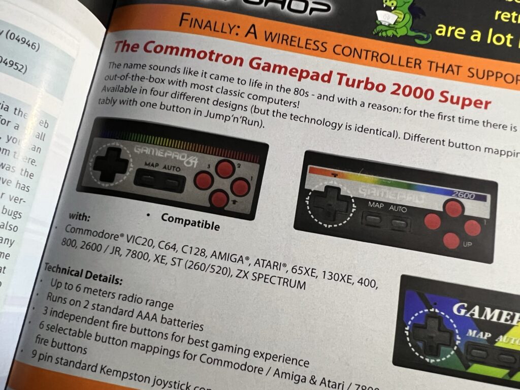
I spotted this wireless Amiga gamepad in an advert in the latest issue of Amiga Future magazine and ordered myself one immediately. Reading a physical Amiga magazine in 2023, seeing an advert in it and actually being able to order the item in that advert is a pretty special experience for me as a retro gamer. Normally when browsing through old Amiga magazines I see adverts for products and from suppliers that are long gone, but this was like being back in the early 1990’s all over again!


wireless Amiga gamepad

Advert in Amiga Future Magazine.


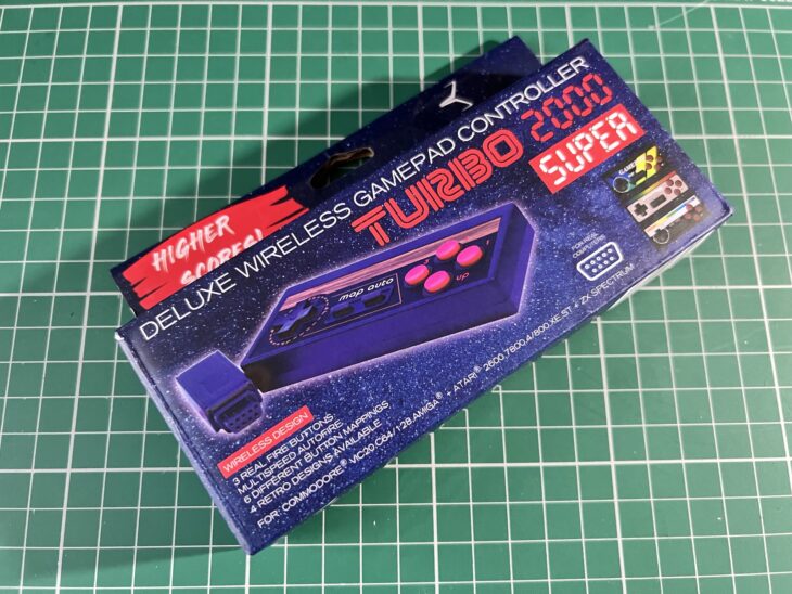
It’s full name is the “TURBO 2000 Super – Deluxe Wireless GamePad Controller” which is ridiculously OTT in a loveable 80’s kind of way. I picked mine up from their eBay web store but they’re available elsewhere online from other retro retailers too.
 

wireless Amiga gamepad

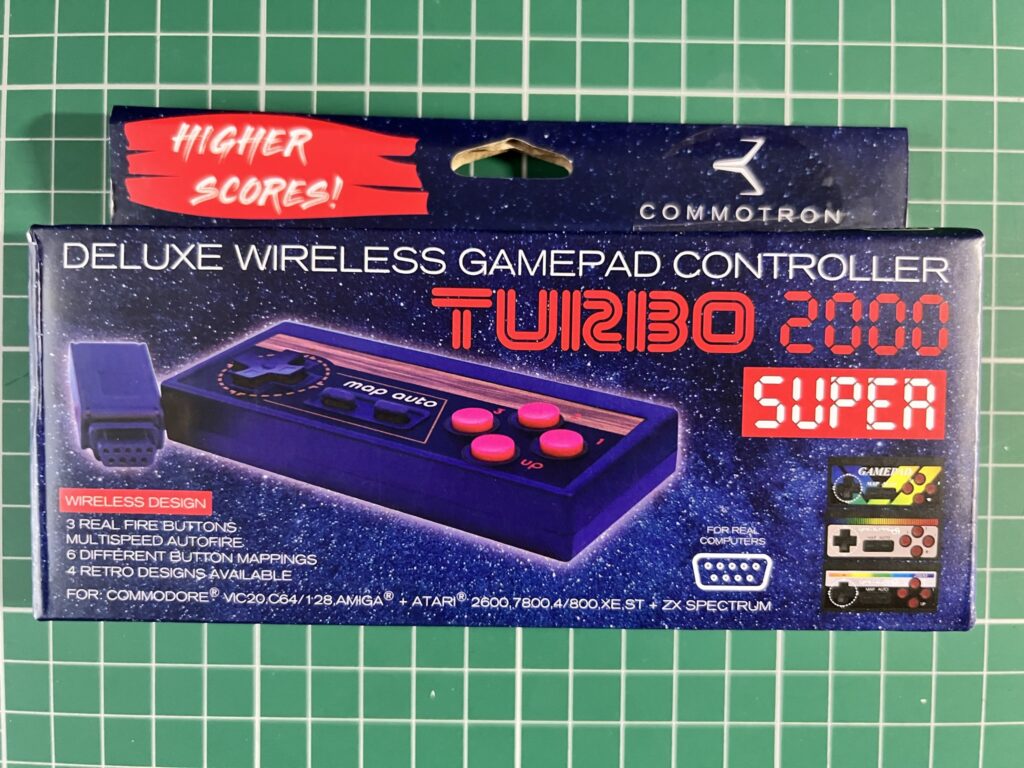
The box front.
 

Despite coming from Germany delivery took less than a week and I had no import fees to pay. Yippee! 🙂


wireless Amiga gamepad

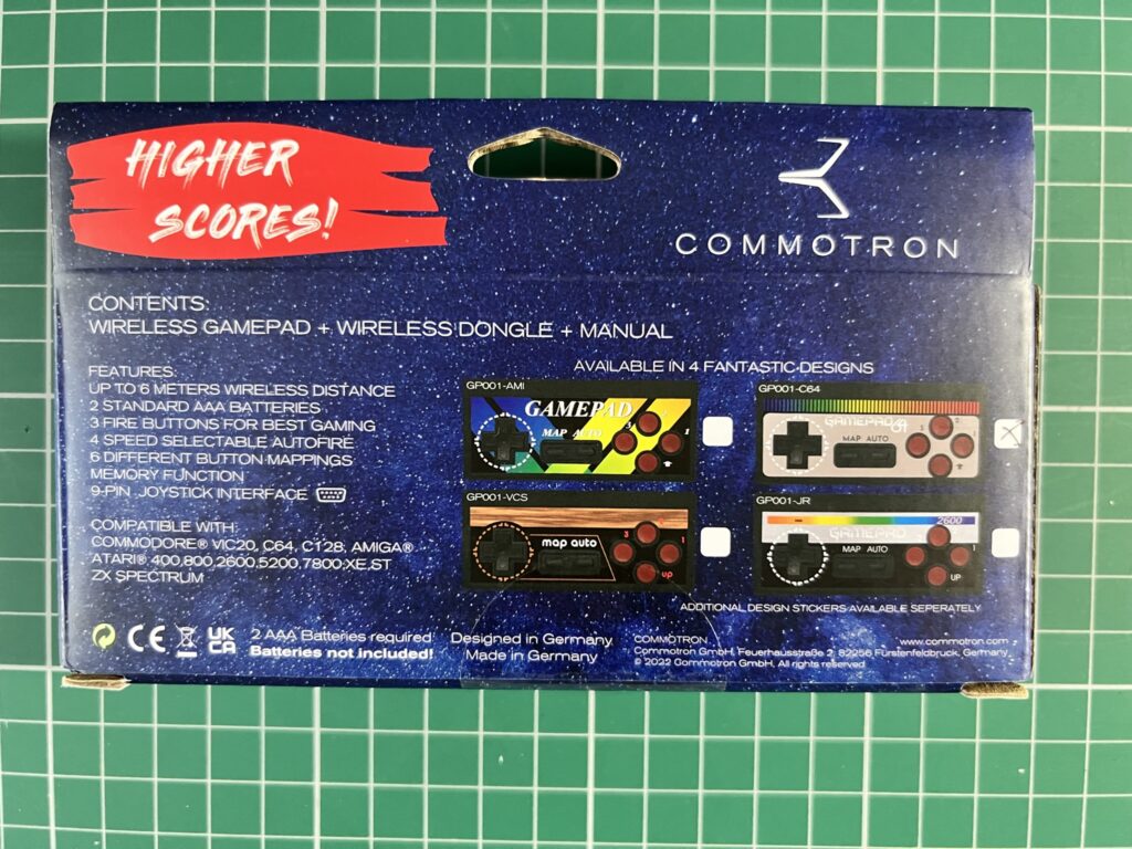
Back of the Box.


It came packaged in a pretty slick and colourful box that definitely wouldn’t look out of place on the shelf in your local game store.


Batteries Not Included

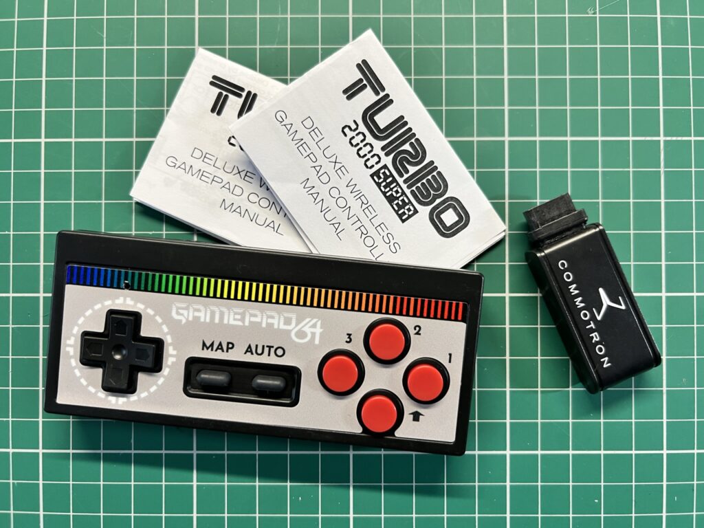
Opening up the box reveals a couple of instruction sheets, a dongle with a standard 9-pin DSub plug and of course the gamepad itself.


wireless Amiga gamepad

Everything you get inside the box.


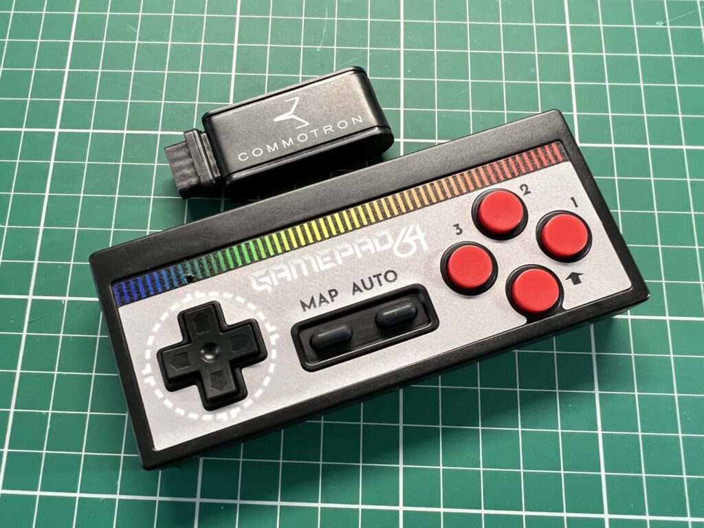
They actually make four different versions of the gamepad for the Amiga, C64, Atari VCS and Atari 2600. They’re all the same physical device though, it’s just the vinyl sticker on the controller that differs for each version.


wireless Amiga gamepad

The wireless dongle and gamepad.


I chose the C64 themed controller as the colours just appealed to me the most.


wireless Amiga gamepad

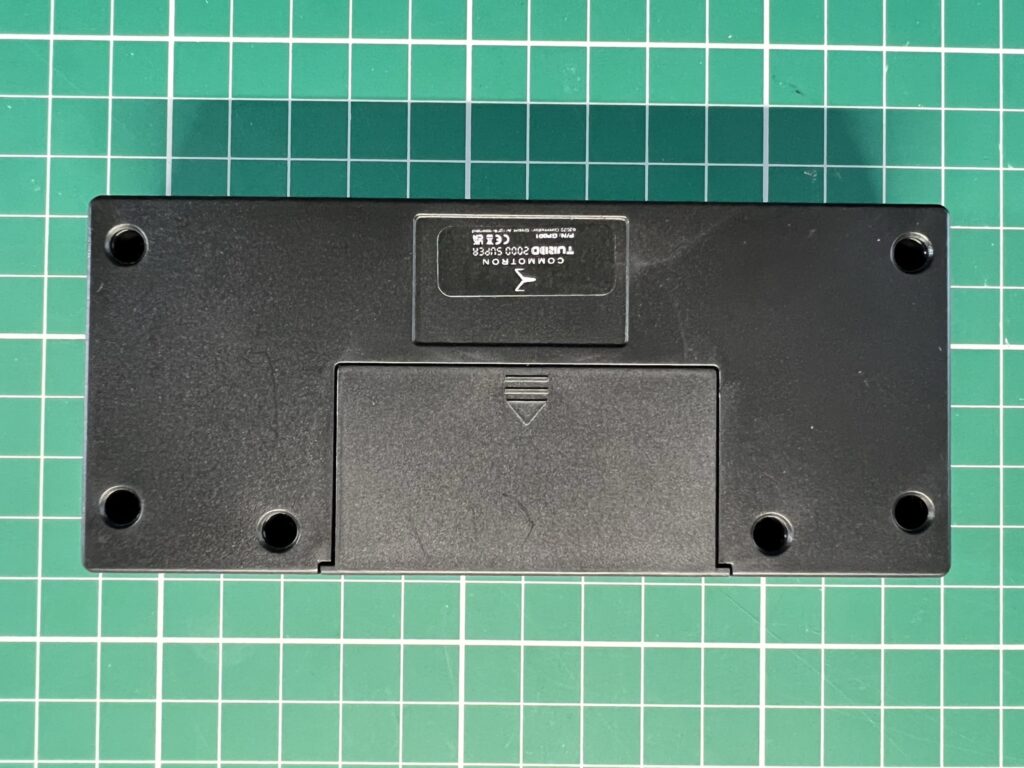
Bottom of the Gamepad.


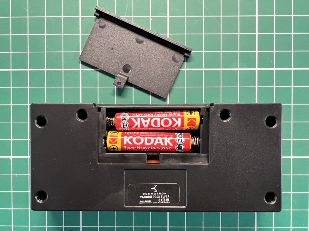
The controller takes 2 AAA batteries (not supplied) that fit into a little compartment on the underside.


wireless Amiga gamepad

AAA Battery Compartment.


Connecting the Gamepad to the Amiga

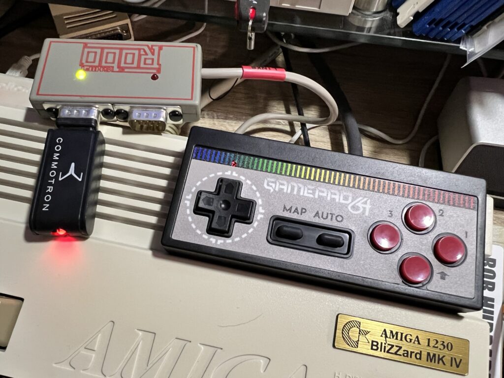
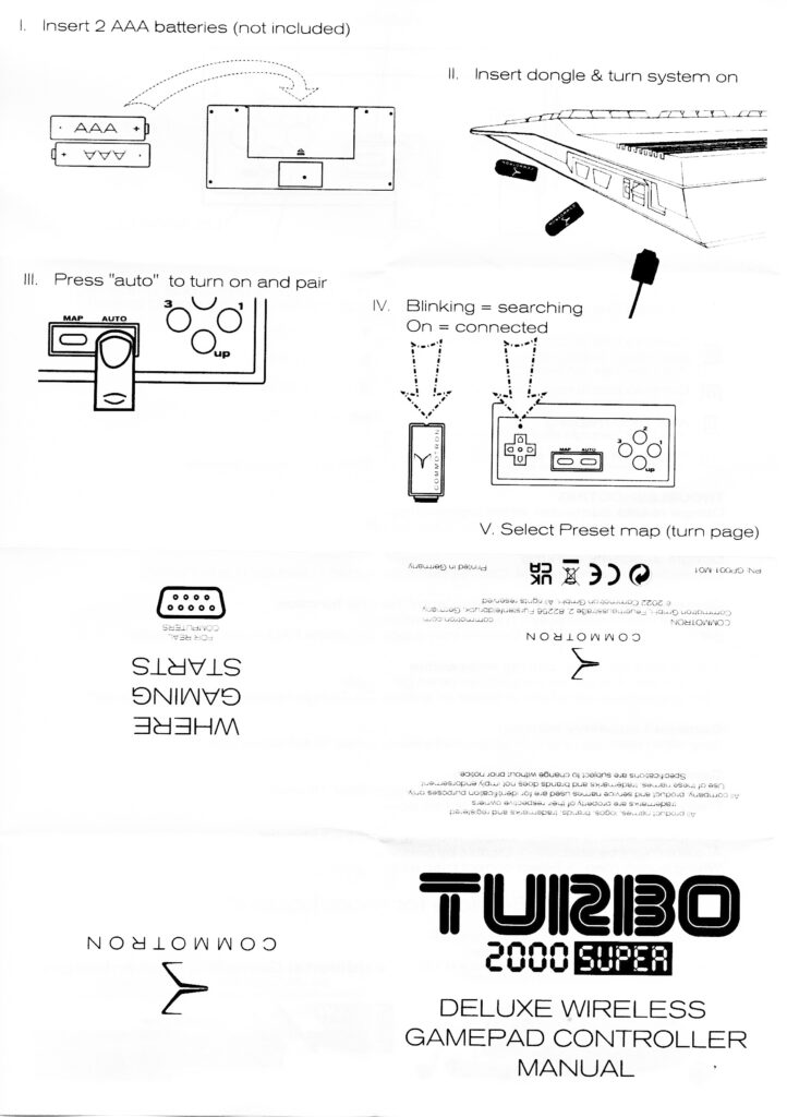
Connecting the dongle and gamepad to the Amiga could not have been any simpler. You just plug the dongle into the joystick port as normal (or in my case my Roboshift), power on the Amiga and then power on the gamepad.


wireless Amiga gamepad

Hooking the Wireless Dongle up to my Roboshift device.


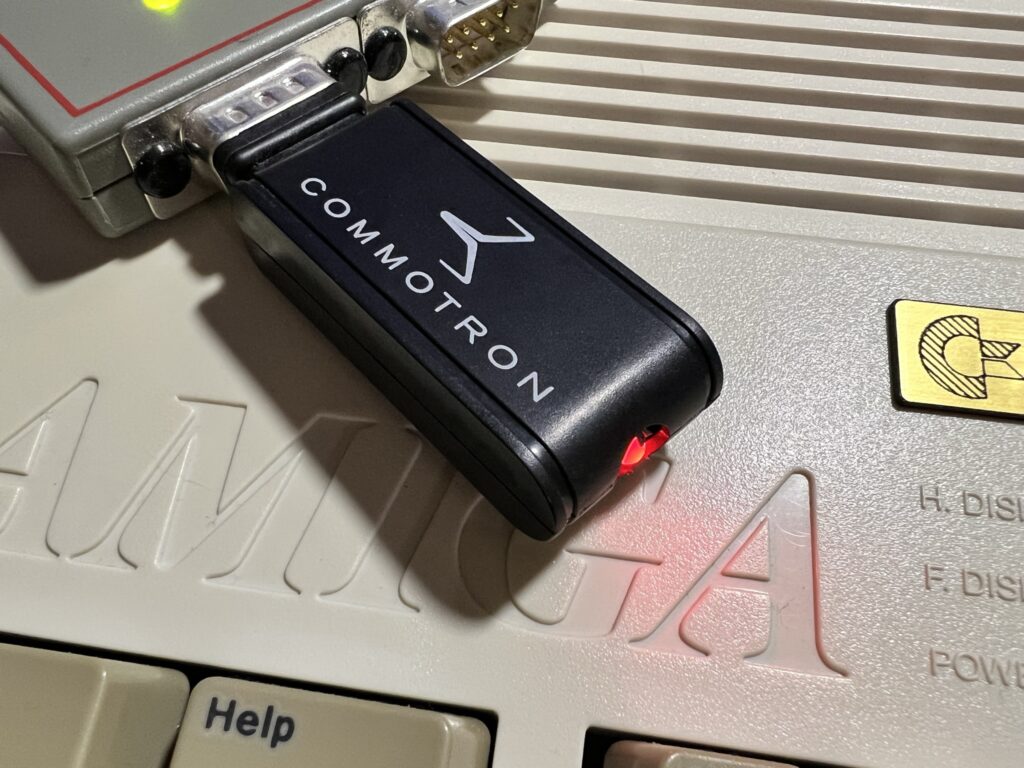
When you first plug the dongle in and power on your Amiga, a red LED on the device flashes signifying that it is trying to pair with the controller.


wireless Amiga gamepad

The Wireless Dongle.


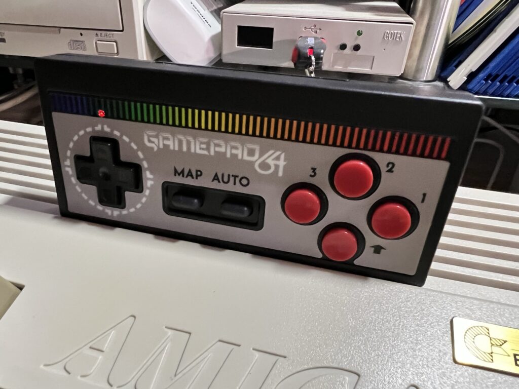
As soon as I powered on the gamepad (which also had a small red LED above the D-Pad) both LED’s became solid red right away.


wireless Amiga gamepad

Notice the little Power/Connectivity LED above the D-Pad.


What’s it like to use?

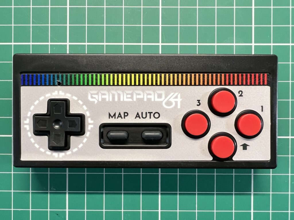
The gamepad is well constructed and nicely finished in a textured matte black plastic. The vinyl sticker on the front is really well made and looks professional. The textured finish makes it easy to grip and having a set of batteries inside it means it has a nice bit of weight to it.


wireless Amiga gamepad

Close-up of the buttons.


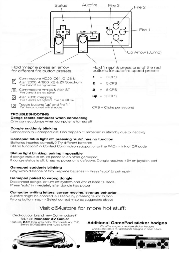
The gamepad features 3 fire buttons (labelled 1, 2 & 3) and a dedicated ‘UP’ button which is a real boon in platform games. The ‘MAP’ button is used to switch around the fire buttons depending on your preference or system being used. It can also be used to switch the ‘UP’ button with fire button 1 should you wish. The ‘AUTO’ button toggles the auto-fire feature on and off. 4 different auto-fire speeds are configurable on the pad; 1, 5, 8 and 13 ‘clicks per second’.

The D-Pad is very responsive and easy to operate without accidentally triggering a diagonal direction unless you actually want to. The fire buttons are quite stiffly sprung and require a firm push to depress which gives plenty of tactile feedback. It did take me a little while to get used to though. Compared to say an Xbox or PlayStation controller they require much more pressure to operate.
 

Turrican 2 AGA

Turrican 2 AGA


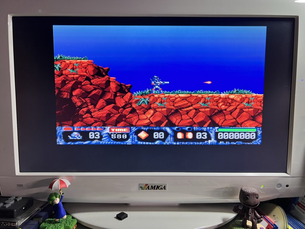
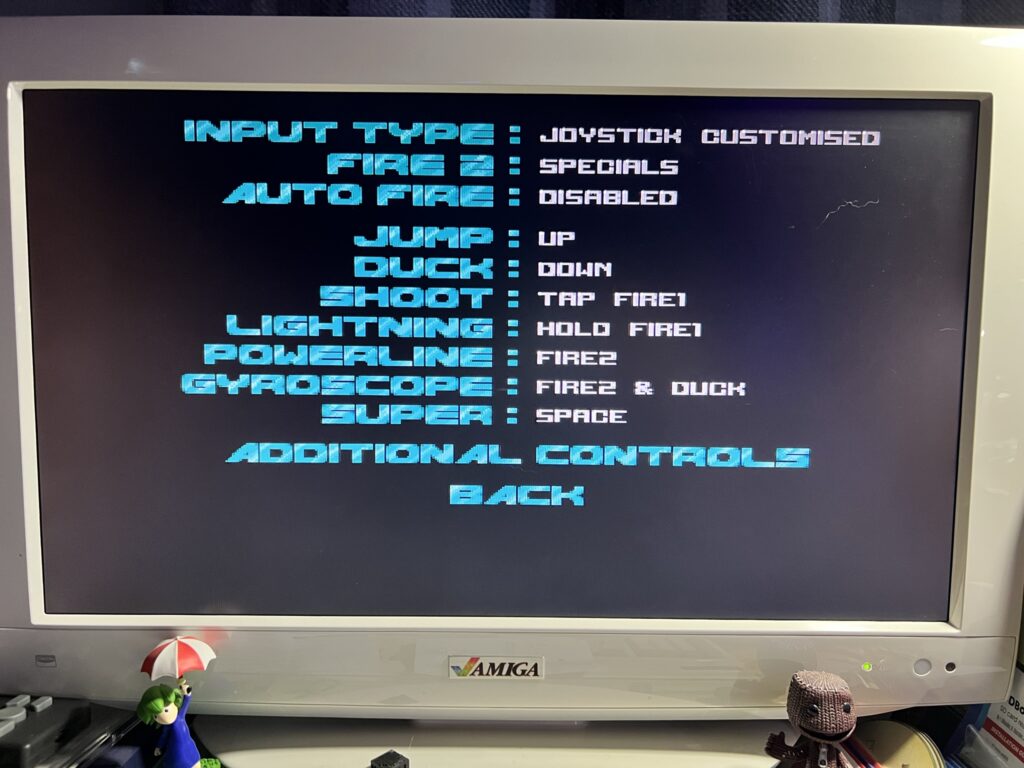
Having 2 fire buttons that work on the Amiga is terrific. Playing the new Turrican 2 AGA for example (awesome game by the way) is so much better when you have the 2nd fire button to help trigger extra weapons/abilities instead of having to reach for the keyboard all the time!


Turrican 2 AGA

Turrican 2 AGA – 2nd Fire Button Configuration.,


This gamepad would be equally awesome for games that support 2 fire buttons on the C64 too. Games like Super Mario Bros 64 and Chase HQ 2 for example.

Another useful feature is that the gamepad turns itself off after a period of inactivity to conserve battery life. Turning it back on just requires a quick press of the ‘AUTO’ button for near instantaneous reconnection.


Final Thoughts

This is an awesome controller and I’m so glad I bought it. I have a ton of retro joysticks and gamepads now but this one has quickly become my favourite. The combination of auto-fire, configurable extra fire buttons and of course the wireless capability means it’s a no-brainer for me. It’s reasonably priced too, coming in at around the same level you would expect to pay for an Xbox or PlayStation controller. Considering this is a low volume product I think the price is very fair indeed.

Needless to say I’m going to order some more so I can leave one permanently attached to each of my Commodore machines! Highly recommended.


FYI

I’ve included scans of the instructions below in case anyone is curious about exactly how the button mapping or pairing works.


Commodore 64 IRQ LED Mod

This Commodore 64 IRQ LED mod is a fun little hack that I spotted on eBay last year. Since my C64 mainboard has just come back from being re-capped I finally took the opportunity to fit this whilst I had the case open.

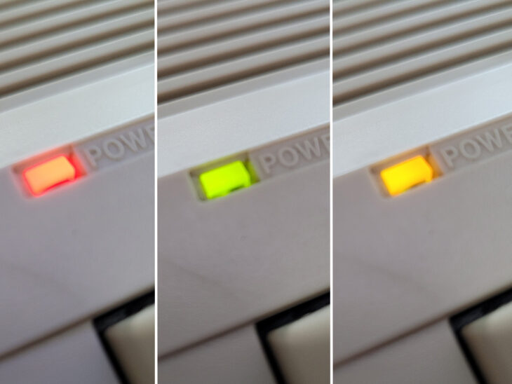
It’s a very simple little device that changes the colour of the C64 (or VIC20) power LED according to IRQ activity. When the computer is just idling the LED will glow red as usual. However when the CPU is active and generating interrupt requests (IRQ’s) the colour changes to green. This allows you to instantly see at a glance if your C64 is doing something. Anything that causes rapid IRQ’s will actually make the LED appear to be orange as it flicks rapidly between red and green.


Commodore 64 IRQ LED Mod

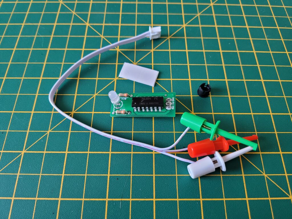
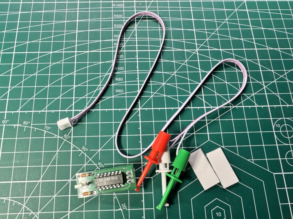
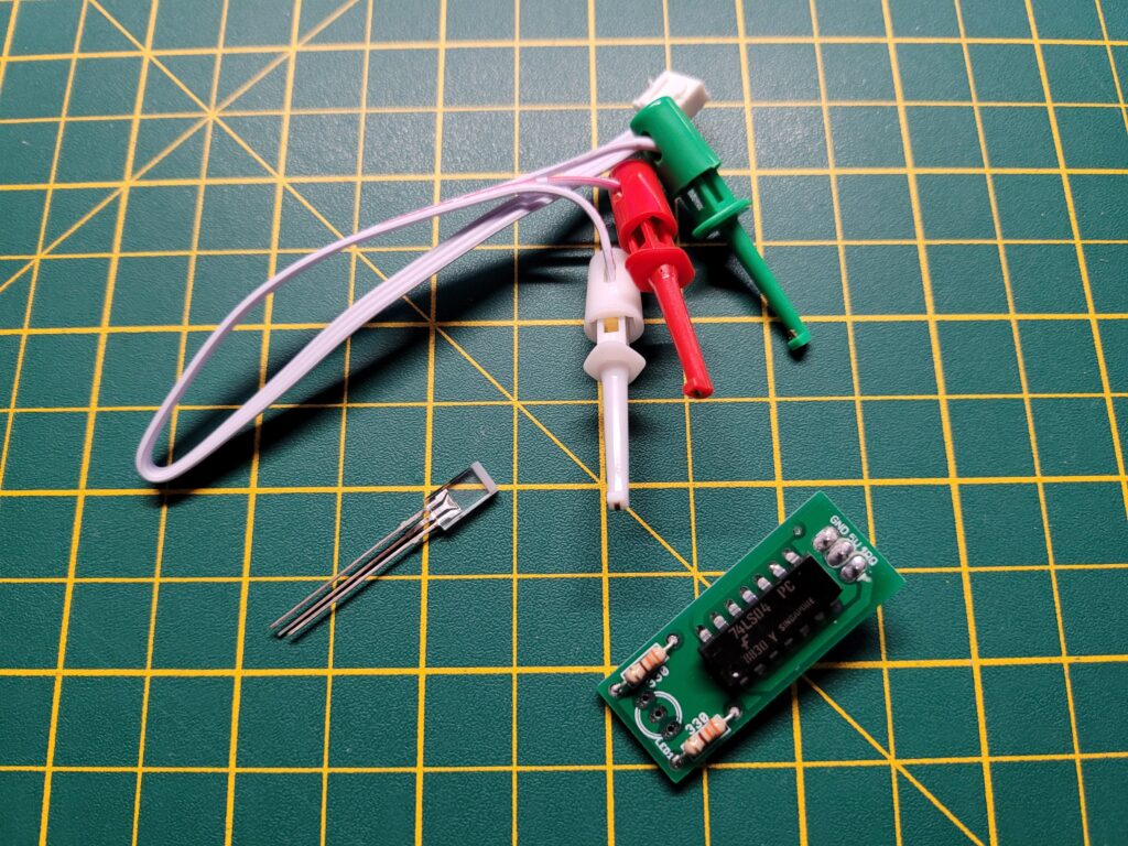
Everything supplied in the regular breadbin kit.


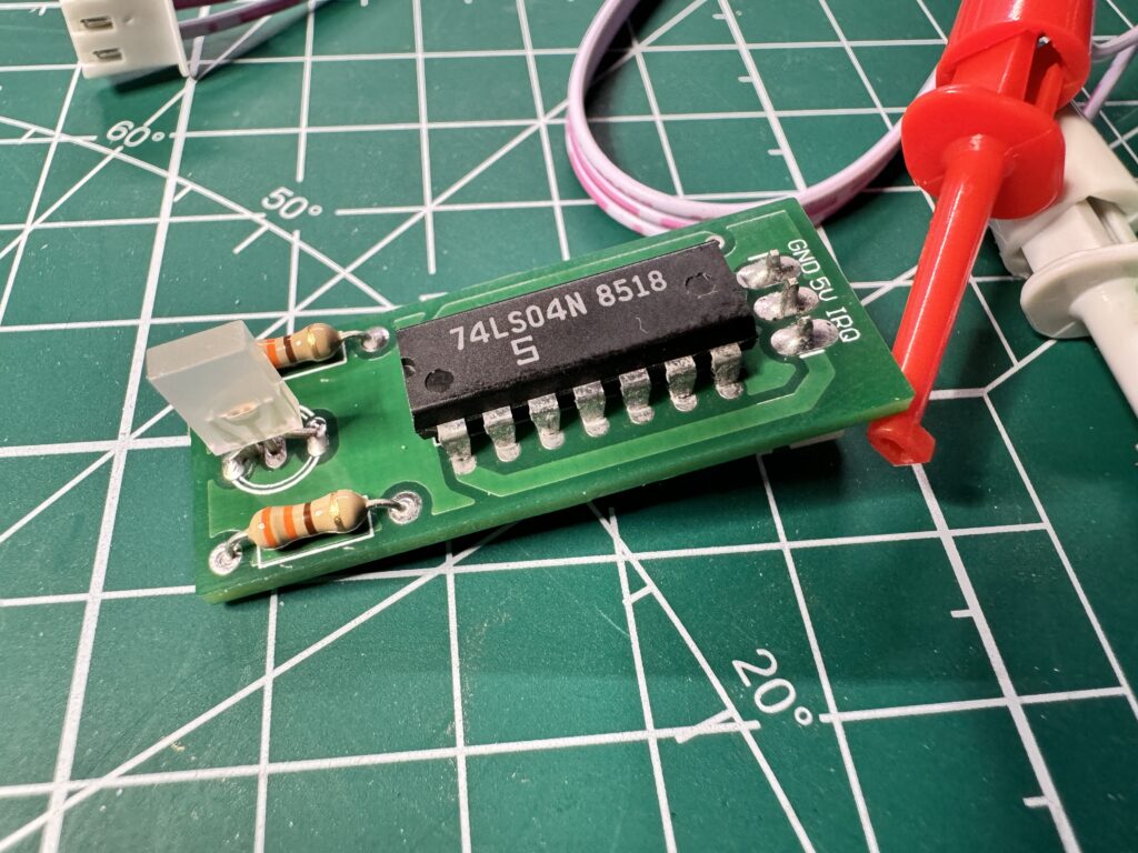
I picked up two of the devices, one for my 64 and the other for my VIC. I should point out that this isn’t a destructive hack. Nothing is permanently altered or damaged in any way and it can easily be reversed if desired. The device itself is really simple and there’s (usually) no soldering required. It consists of a tiny circuit board containing an LED, a couple of resistors and a single chip that detects the IRQ signals and triggers the LED colour changes. Connected to the board are 3 wires that are terminated with IC clips. These clips attach to the cartridge port pins and this is how the device monitors IRQ’s.


Breadbin Install


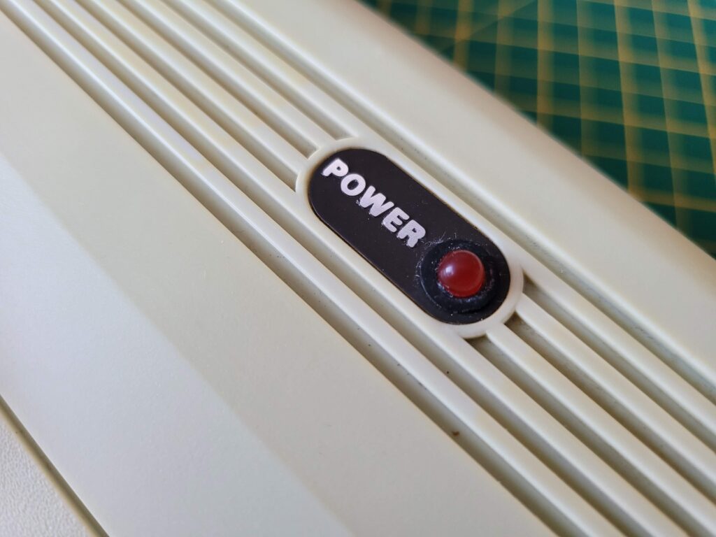
VIC20 Power LED.

Original VIC20 Power LED.


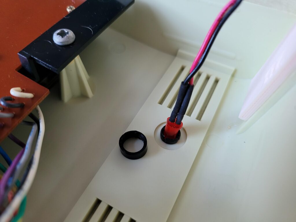
For breadbin C64’s and VIC20 computers fitment is extremely simple. You just unplug and remove the existing power LED and replace it with the little circuit board. There’s a small black plastic ring on the inside that needs pulling off and then the LED should push into the case from the outside with a little bit of force.


Removing a VIC20 Power LED.

Removing a breadbin C64/VIC20 Power LED.


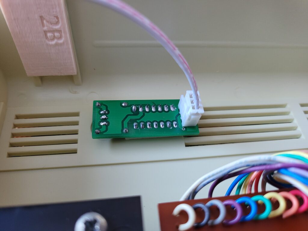
There’s a spare black plastic collar for mounting the LED supplied in the kit in case you break the existing one. Also supplied is a little double-sided adhesive pad that you can use to fix the board in place. The new LED will need a little pressure to snap it into place and with the help of the adhesive pad it should be held nice and secure.


Commodore 64 IRQ LED Mod

Fitted board – held in place with a double-sided sticky pad sandwiched between the case and the chip.


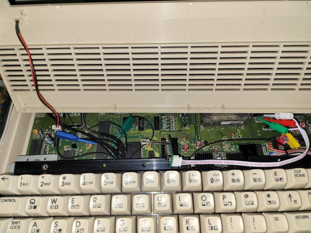
Now it’s just a matter of wiring the board up. The 3 wires need to be attached to the front row of cartridge port pins using the IC clips as indicated below.


Commodore 64 IRQ LED Mod

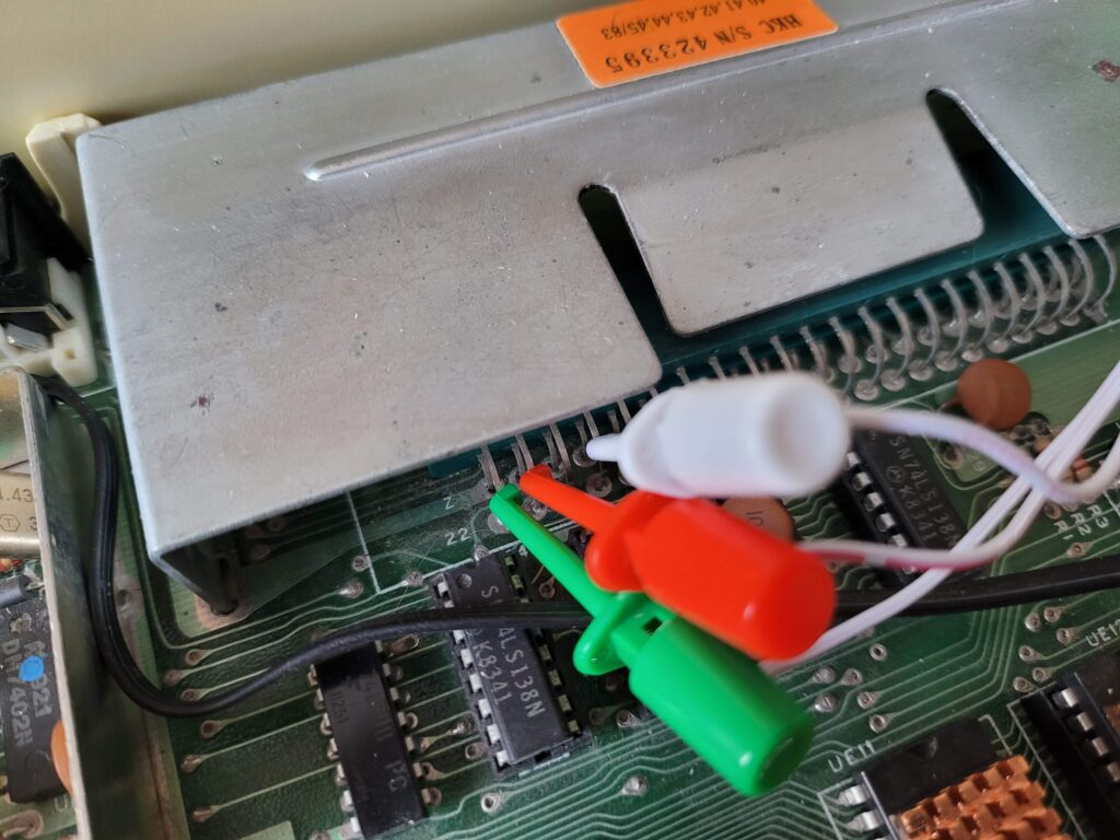
IC clips connected to VIC20 cartridge port.


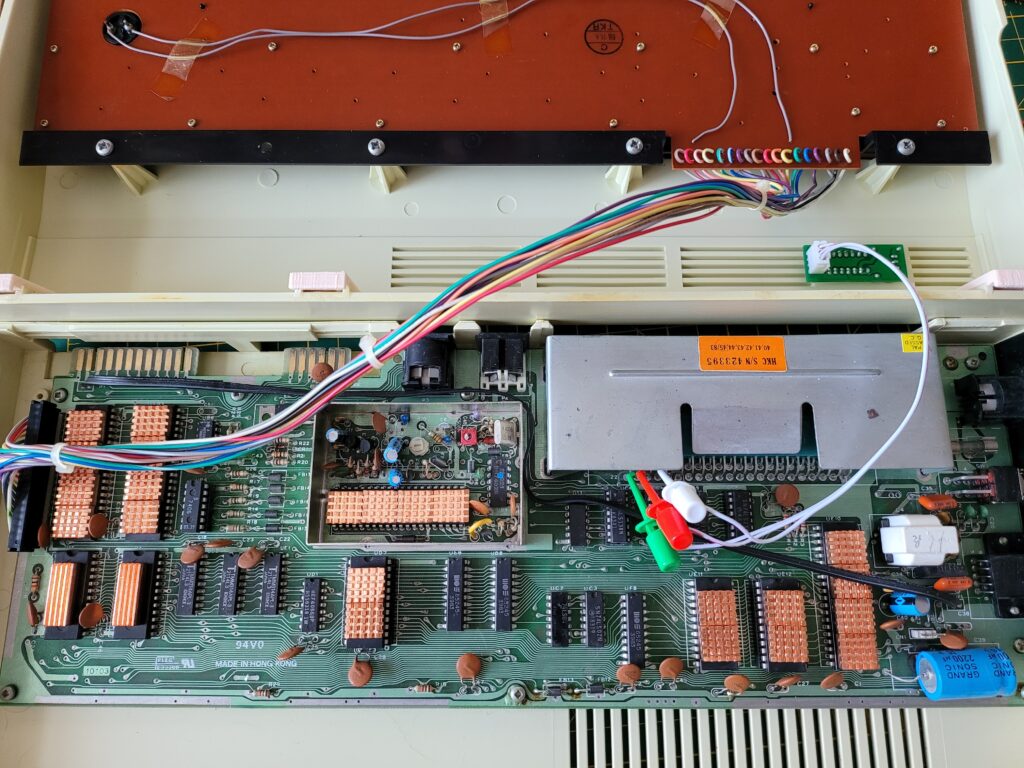
One the VIC20 the green clip goes onto pin 22 (Ground), Red – Pin 21 (+5V) and White – Pin 19 (IRQ).

On the C64 it gets wired up as follows; Green – Pin 1 (Ground), Red – Pin 3 (+5V), White – Pin 4 (IRQ).


Commodore 64 IRQ LED Mod

View showing the completed mod fitted.


Time for the moment of truth – putting the case back together and giving it a test drive. The LED in my kit had been soldered on in reverse so when my VIC was idle it lit up green and when busy it changed to red. I could have solved this by de-soldering it and flipping it round but it really doesn’t bother me so I left it alone. Other than that it works exactly as advertised and I’m really happy with the result.


This slideshow requires JavaScript.


C64C Install


UPDATE [March 2024]

Tim over at SharewarePlus now produces a version specifically for the C64C too incorporating a rectangular LED and also a much longer set of cables to allow the clips to actually reach the cartridge port as the LED is on the opposite side to the older ‘breadbin’ style machines.


C64C Version.


This makes the installation process just as simple as it was for the breadbin case one.


Close-up view of the C64C version with rectangular LED.


I’ll leave the details of my original installation modification below just in case anyone else finds themselves needing to fit a round peg into a rectangular hole. However realistically this info is now obsolete so long as you are getting one after March 2024 as you can just choose the right one for the job when you buy it.


ORIGINAL INSTALL

I hinted earlier that non-breadbin installs aren’t quite so simple. I have a C64C and as supplied the mod will not work with this model. There’s a couple of reasons for this. The most obvious being the C64C has a rectangular LED rather than the usual round one found in Breadbin style machines.


Commodore 64 IRQ LED Mod

Board supplied without a round LED and a rectangular one waiting to be fitted.


The other problem becomes apparent once you open up the case. As can be seen in the photo below the power LED is at the opposite end of the case to the cartridge port so the supplied wires are too short.


Commodore 64 IRQ LED Mod

Here you can see that the supplied wires in the kit only reach half-way across the board.


Fortunately these issues are easy to sort. I mentioned about the LED to the seller (Tim Harris who runs Shareware Plus) and he kindly supplied the board without an LED fitted so I could fit a rectangular one myself. These ones here are a good fit: rectangular LED’s on eBay.


Commodore 64 IRQ LED Mod

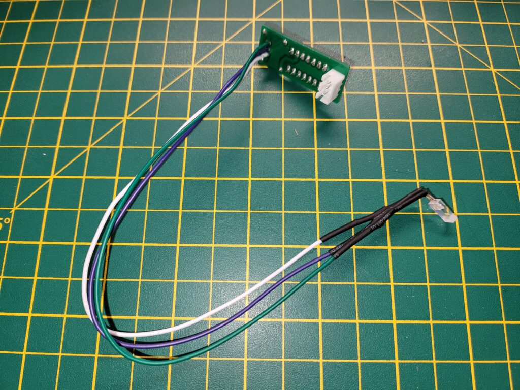
LED fitted to 10′ long wires to allow it reach across.


In order for the LED to fit in the existing hole I soldered it to three 10 inch lengths of wire and then soldered the wires to the circuit board. I fitted some heat shrink tubing over the joints to insulate them. This allowed me to mount the circuit board close to the cartridge port and also have the LED in the correct place.


Commodore 64 IRQ LED Mod

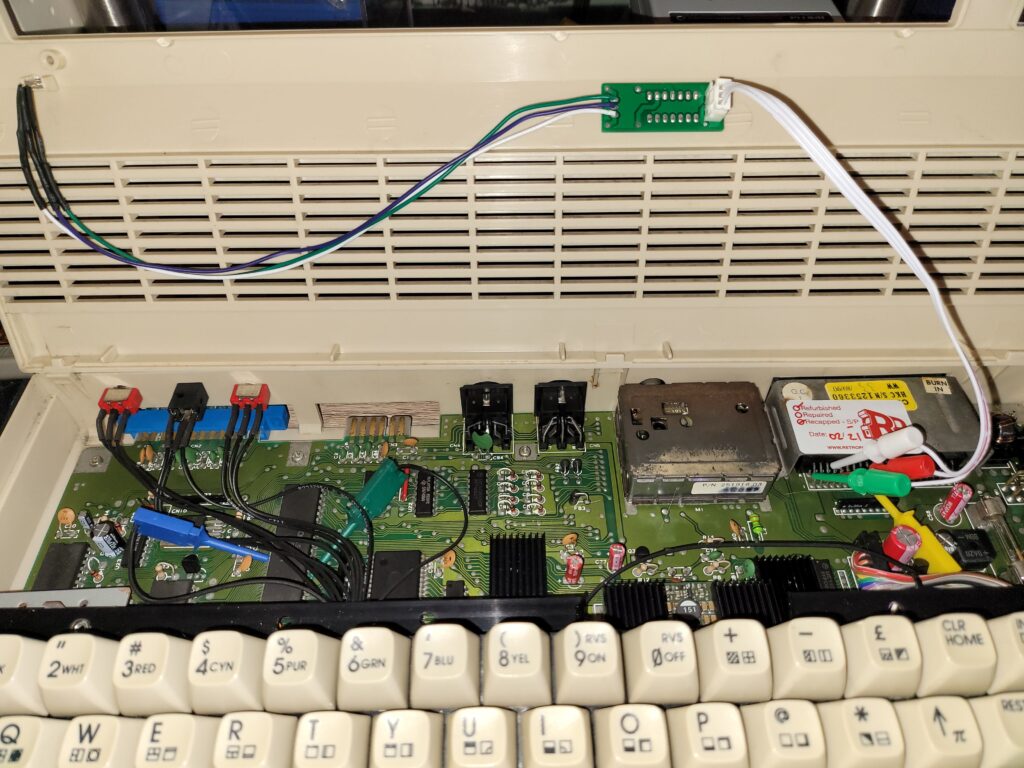
Here you can see the mod fully fitted and wired up. Note there are several other IC clips on this photo – these are from my SIDFX (twin SID chips).


I attached the board with a small double-sided sticky pad to hold it in place. I also carefully bent the wires on the LED 90 degrees so the cables would lie flat along the top of the case.

The IC clips were connected to the cartridge port pins as follows:

  • Green – Pin 1 (Ground)
  • Red – Pin 3 (+5V)
  • White – Pin 4 (IRQ)


Verdict

After giving it all a quick test I put the case back together and had a play around with it. When idle the LED lights up red as normal – a much more vivid red than the photos show. When the CPU is actively generating an IRQ such as when loading off a disk the LED with light green. Rapid IRQ activity that can happen when playing a game makes the LED appear orange.

I’m really impressed with this little mod. It’s one of those things that’s kind of pointless but also completely essential at the same time. I love having a visual indicator that my computer is doing something and during loading or saving operations it functions as a kind of drive activity light.

You can see it working clearly in the video below, taken whilst I was loading a program off a floppy disk.


If you enjoy tinkering and like the idea of having an activity light on your C64 or VIC then I can thoroughly recommend this. Did I mention that it costs less than a tenner too? A real no-brainer for me. You can pick up either version from Tim over at SharewarePlus.

VIC20 Game Box Preservation

It’s winter here in the UK so recently I decided to spend a particularly cold and rainy afternoon on a little VIC20 game box preservation project I’ve been meaning to do for some time.

Why did I want to do this?

Unfortunately, unlike Sega games which came in sturdy plastic clamshell boxes, Commodore cartridges were supplied in flimsy cardboard boxes. Consequently many of these have not stood the test of time – as a quick glance at all the box-less cartridges on eBay will attest to. I’m really proud that my collection has remained largely in tact for almost 40 years but for them to survive another 40 I figured they’d need a little helping hand.

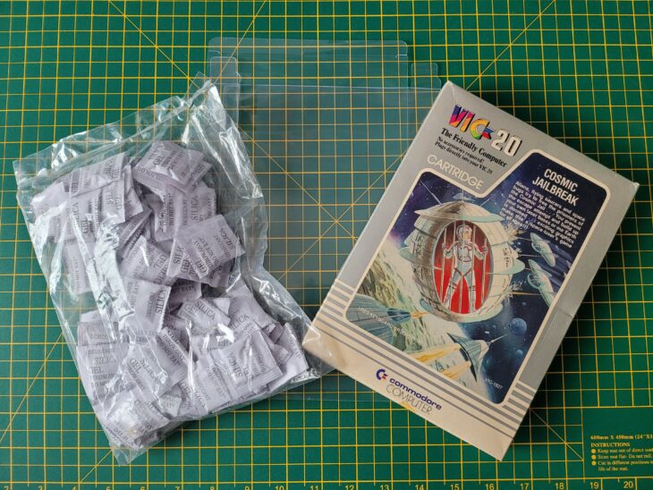
I’d already found some great looking box protectors on eBay and also picked up some sachets of Silica Gel off Amazon for good measure. All I needed was a some time to apply them to my VIC20 cartridge collection.


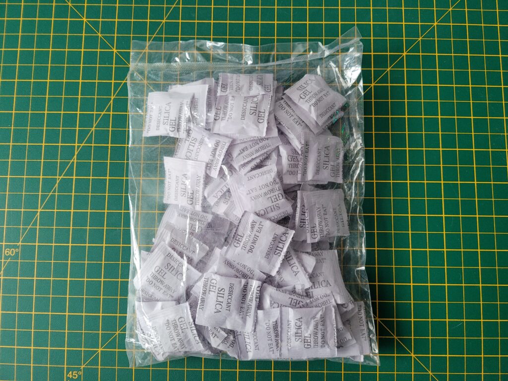
Sachets of Silica Gel

Sachets of Silica Gel


The Silica Gel sachets came in a sealed bag of 100. The moment you open the pack they will start absorbing any moisture in the air so it’s important to minimise their exposure and keep them in a sealed container once opened.


VIC20 Box Protector

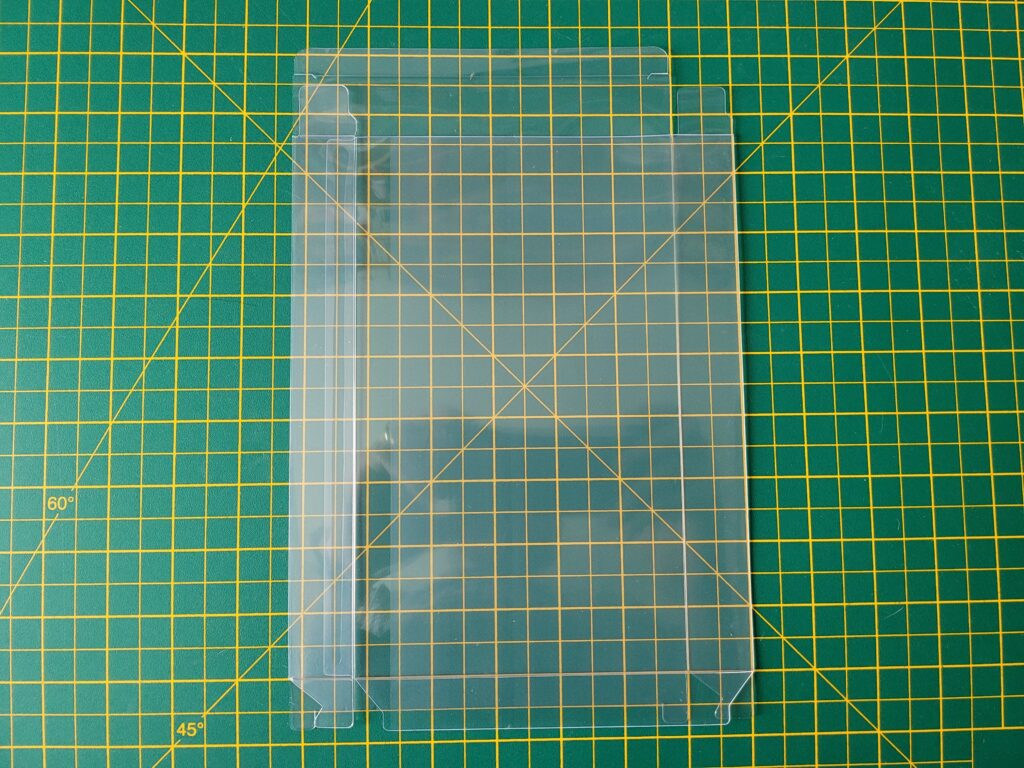
A VIC20 Box Protector folded flat (this is how they are supplied).


The Box Protectors

The box protectors are made of PET material which according to Wikipedia “makes a good gas and fair moisture barrier, as well as a good barrier to alcohol (requires additional “barrier” treatment) and solvents. It is strong and impact-resistant”. The boxes were supplied with a protective film on them to prevent scratches in transit. I have to admit I hadn’t realised this at first and was wondering why they looked slightly opaque. When the penny dropped and I removed the film they were crystal clear. You can see the difference clearly in the photos below.


This slideshow requires JavaScript.


Protect and Preserve

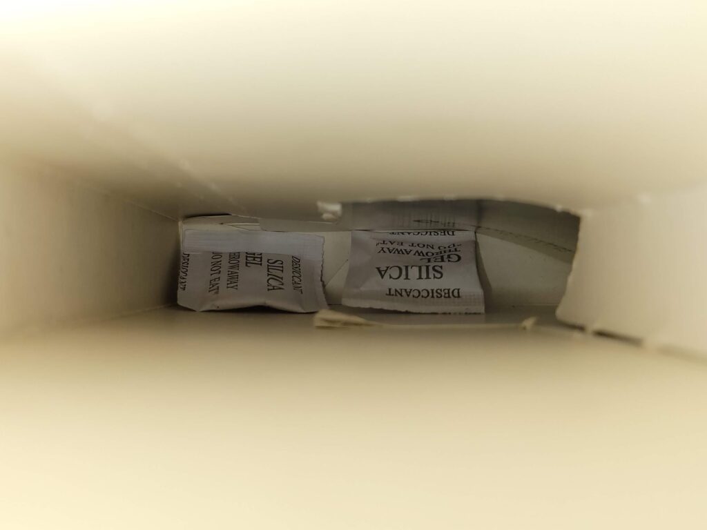
After ensuring that my game boxes were dust free and that the cartridge inside was similarly clean I added a couple of sachets of gel inside each box. The plastic box protectors should do a good job of protecting the contents from the environment but they’re not air-tight so the gel will absorb any moisture that makes its way inside. This should prevent any mould from forming on the contents. At some point in the future the sachets will need replacing but as I’m keeping the games in a nice warm room they should be fine for years.


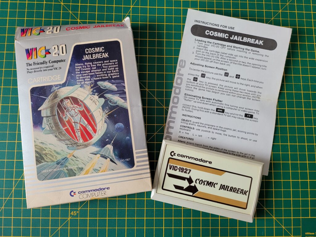
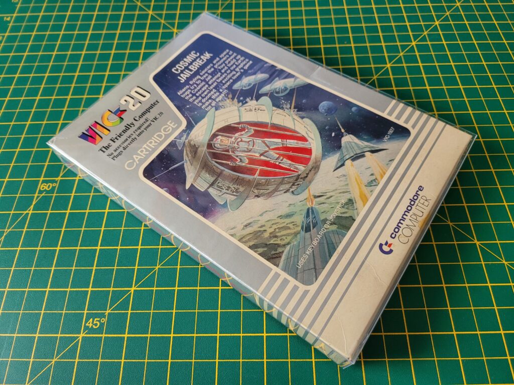
VIC20 Cosmic Jailbreak Cartridge

Game box, with the cartridge and instruction manual laid out alongside it.


If I was placing them in a damp, cold basement, loft or garage then they would need replacing far sooner. However in those locations the games would need to be sealed in an air-tight box too.


VIC20 Game Box Preservation

Silica gel sachets placed inside the bottom of box.


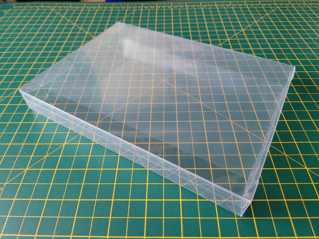
The protective cases were supplied flat-packed so needed folding into shape before they could be used. I found this really easy to do and it took less than a minute per box.


VIC20 Game Box Preservation

A completed box… with the protective film still attached in this photo!


Now it was simply a matter of carefully sliding the game box into the protective case. The cases were a very snug fit so I did need to ensure the box went in straight before it would fit inside.


VIC20 Game Box Preservation

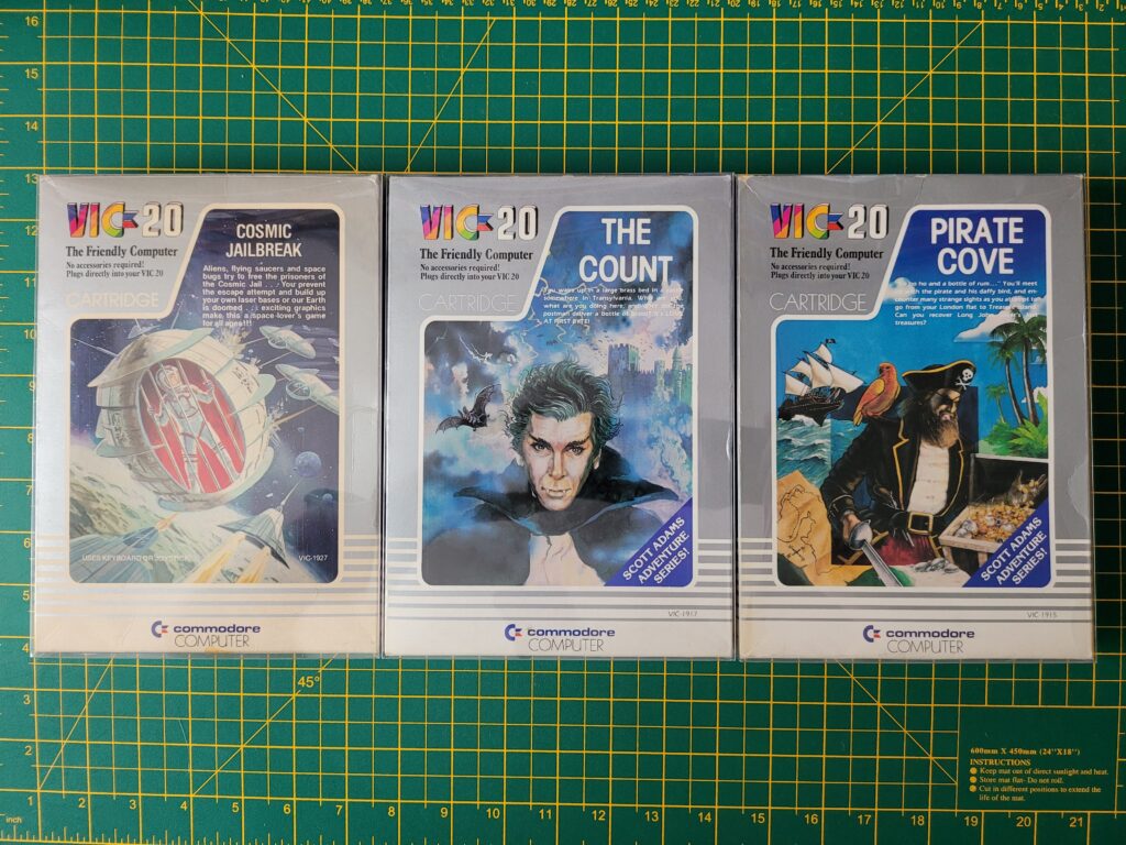
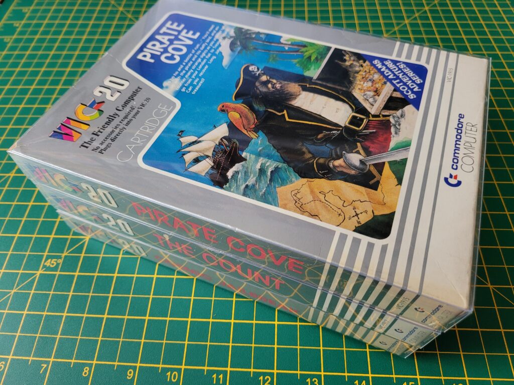
Game box fitted inside a protective case.


There is a seam down one edge (where the box spine is) so I made sure to position that at the back when displaying them on my shelf.


VIC20 Game Box Preservation

Notice how the game on the far left looks slightly opaque – this box still had the protective film on it. It has been removed from the other two.


I think the games look terrific inside the boxes and from most angles you can’t even tell they’re inside a cover.  In fact I’d go as far as saying some of my games looked much better inside the protective cases. Take the Menagerie game shown below which has suffered some box crushing and creasing over the years.


Before…


This slideshow requires JavaScript.


Because the protective covers are such a snug fit they actually force the game boxes back into their original shape when inserted. In effect the covers act as a kind of exoskeleton, almost eliminating the effect of the creasing. The creases are still there of course but just far less noticeable now.


After…


This slideshow requires JavaScript.


All in all I’m really pleased with how this project worked out. It was inexpensive, effective and the whole project only took me a couple of hours to complete. That included taking the photos for this post too.


VIC20 Game Box Preservation

A bunch of VIC20 games in their new protective covers.


My VIC20 games not only look better than before but I feel much happier knowing that I’ve taken steps to ensure they last for another 40 years!


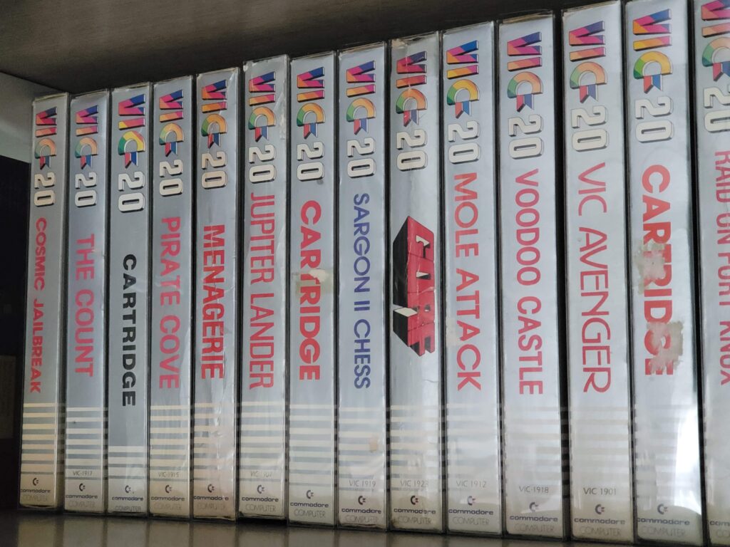
VIC20 Box protectors

Row of protected games on my shelf.

Brucie Bonus

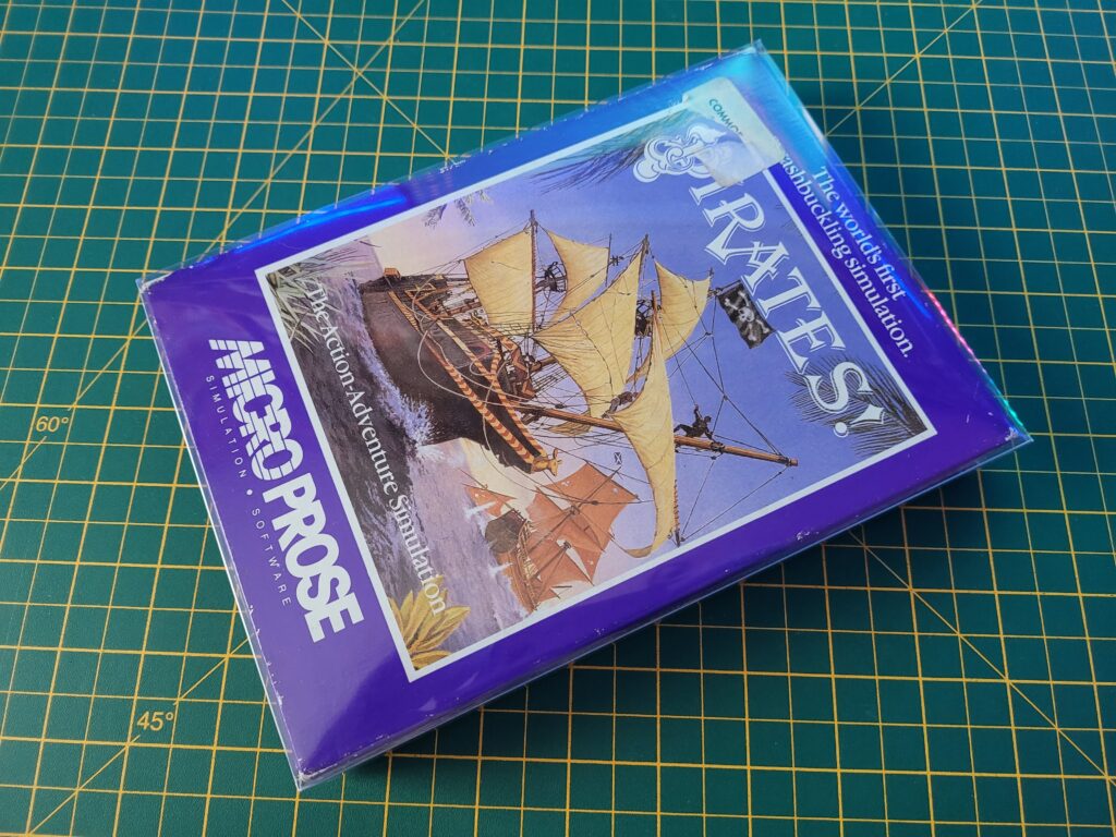
I discovered that the protectors are also a perfect fit for the Commodore 64 Microprose style boxes. This means they’ll also fit similar style boxes from the likes of Rainbird and Level 9. I can see another batch being ordered very soon!


C64 Microprose box protector

The VIC20 box protector also happens to be a perfect fit for the popular Commodore 64 Microprose style game boxes!

iNNEXT USB Game Controller Review

iNNEXT USB Game Controller

Just picked up an iNNEXT USB Game Controller off Amazon to use with my TheC64 Mini and Maxi consoles. Why? Well unfortunately after almost 40 years of faithful service my C64C has started to act up. It’s been crashing and freezing whilst playing games that have always run flawlessly before. I’ve ran my diagnostic cart on it and everything passed so I’m hoping it’s just the electrolytic capacitors. My C64C has never been recapped before so it’s been packaged up carefully and sent away to an expert to get them all replaced. I decided not to attempt it myself as I don’t want to risk causing further damage with my dodgy soldering skills! I’ll know the outcome of this in a couple of weeks when I get it back.

Anyway, in the mean time I still want to be able to play my C64 games without having to resort to the Zip stick wannabe’s that the Mini/Maxi consoles come with. Even though the stick that came with the Maxi is much improved I just prefer a gamepad controller these days.


iNNEXT USB Game Controller

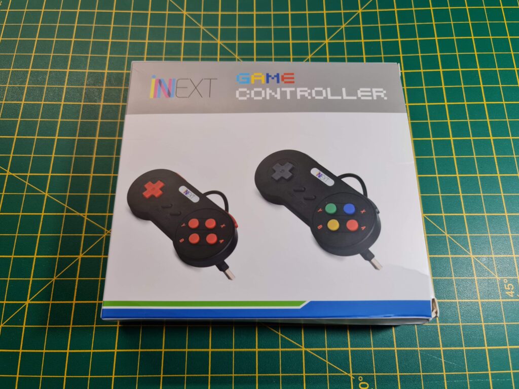
iNNEXT USB Game Controller Packaging


I’m sure there are other controllers out there that will work but I chose these for a number of reasons. The most important one being that in addition to the D-pad they have 8 buttons, matching the number of buttons on TheC64 joystick. They also looked great and came in a pack of 2 for a reasonable price. I was a little apprehensive when purchasing as I wasn’t sure if all the buttons would actually be recognised by the console. This is why I thought I’d share my experience in case anyone else is looking for a similar gamepad for their TheC64’s.


iNNEXT USB Game Controller

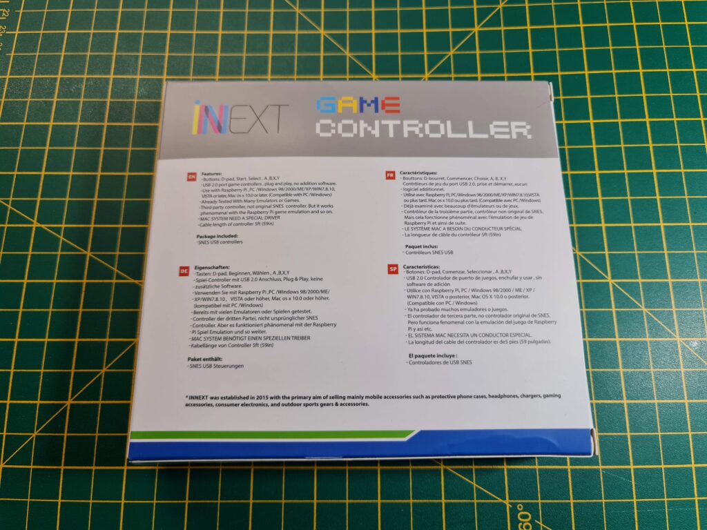
Back of the box.


I was fully expecting a nondescript plain box as is often the case with cheap Chinese goods. However the gamepads came supplied in a surprisingly attractive box featuring product shots of the controllers on the front. The reverse side lists all the gamepad features in multiple languages.


iNNEXT USB Game Controller

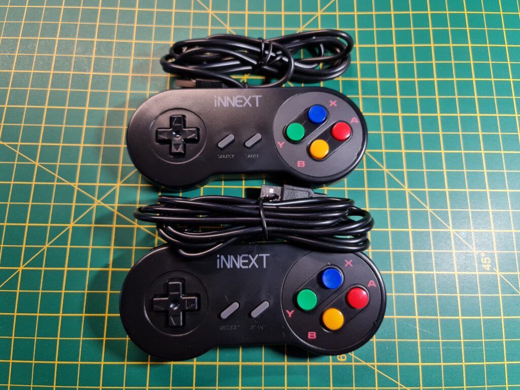
The two controllers unboxed.


A Closer Look

The iNNEXT USB Game controllers themselves are styled like the old SNES gamepads. In addition to the D-Pad they have ‘Select’, ‘Start’, ‘A’, ‘B’, ‘X’, ‘Y’ and two shoulder buttons. Altogether this makes 8 buttons plus the direction controls which matches the configuration of the TheC64 joysticks exactly.


This slideshow requires JavaScript.


Taking a Peek Inside

The build quality of the pads is really good and although they’re pretty lightweight, they feel solid and well constructed. They certainly didn’t creak or flex in my hands, even when I deliberately tried to bend them. The D-Pads worked well and the buttons have a decent tactile feel to them when pressed. They didn’t feel spongey or rubbery so I was never in any doubt as to whether I had pressed one or not. One little feature I appreciated was the contrasting convex and concave buttons for the XY and AB buttons which made it easier to know what I was pressing in low light.


iNNEXT USB Game Controller

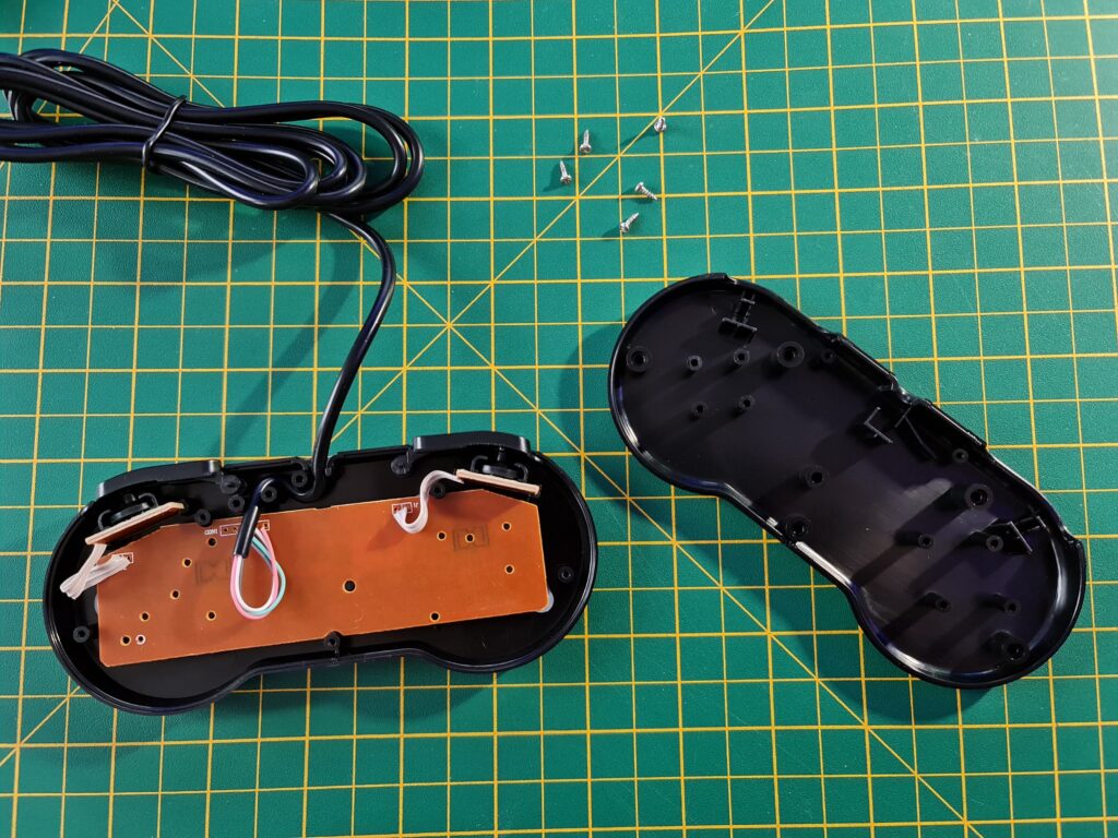
iNNEXT USB Game Controller Internals.


The cable is approximately 5 foot long (1.5m) which I found was more than long enough for my needs. The gamepad shell itself is held together with 5 small philips screws. Naturally my curiosity got the better of me and I took it apart to see what was inside.


iNNEXT USB Game Controller

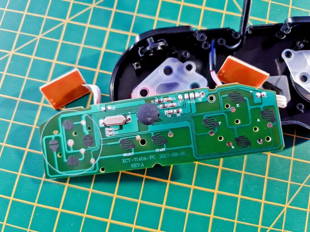
The iNNEXT USB Game Controller PCB.


As I should have expected from a modern piece of electronics, there wasn’t really much to see. Still, at least my curiosity was sated!


iNNEXT USB Game Controller

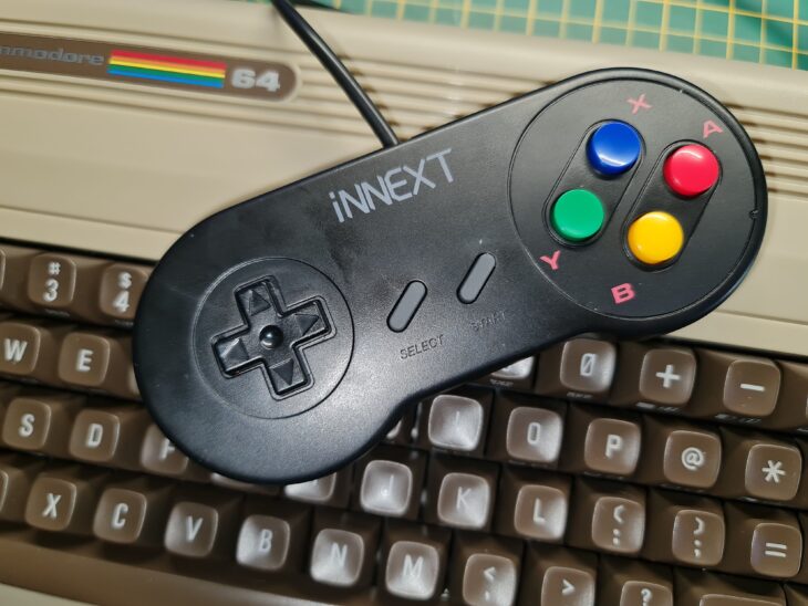
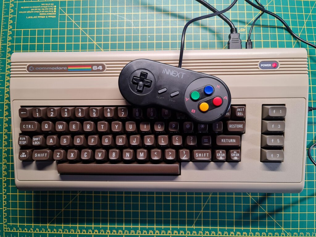
iNNEXT USB Game Controller with TheC64 Maxi*.


*Just in case anyone wants to know where I got the Commodore 64 badge from – check out my post here.


Testing

The controller just worked out of the box with the games I tried on TheC64 Maxi carousel. By default both shoulder buttons are configured as ‘Fire’ buttons which I found worked pretty well. The Start button brings up the ‘save state’ menu whilst X and Y operate the two triangular buttons. The first three round buttons on the base of the Joystick are replicated by the A, B and Select buttons. So that was every one of the joystick buttons replicated successfully.


iNNEXT USB Game Controller

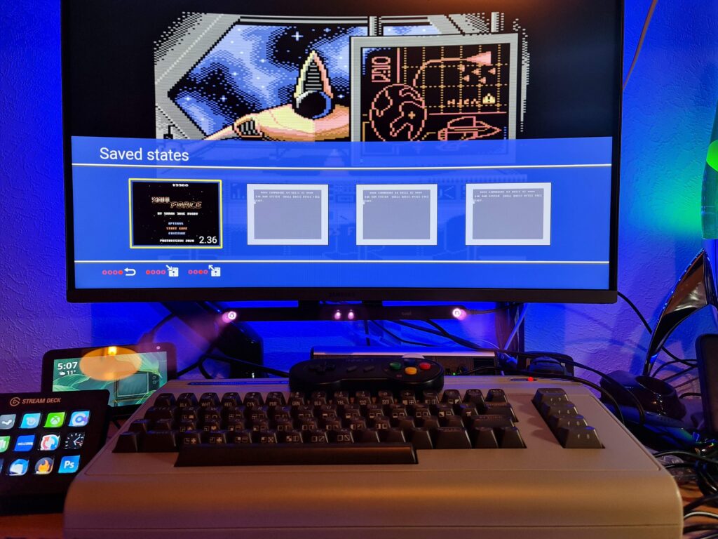
iNNEXT USB Game Controller being used to bring up the Save State menu during a game of Soul Force.


I tried a number of non carousel games off a USB flash drive too like Galencia and Soul Force. Happily I experienced no issues at all with these either. Of course if there had been problems there’s always the option of creating custom .CJM files to change the button configuration for specific games if needs be too.

Perhaps you’d like the left shoulder button to operate the spacebar in Ghostbusters for example? No problem, simply add that to a Ghostbusters.CJM file and you can get your C64 shouting ‘Ghostbusters’ without reaching for the keyboard. This is an even more useful feature when dealing with the keyboard-less TheC64 Mini..

iNNEXT USB Game Controller – Verdict

All in all I think these are terrific gamepads and fulfil their retro gaming duties admirably. They’re very reasonably priced, well built, comfortable to hold and work exactly as I’d hoped. I’ll be keeping the 2nd pad as a spare but there’s no reason why you couldn’t plug them both in and enjoy some 2-player games like Pit Stop II or Spy vs Spy. Oh and they work perfectly on PC as well, whether for native PC gaming or some retro emulator action. Definitely recommended.

Commodore 1530/1531/C2N/Datasette Dust Cover

Datasette dust cover

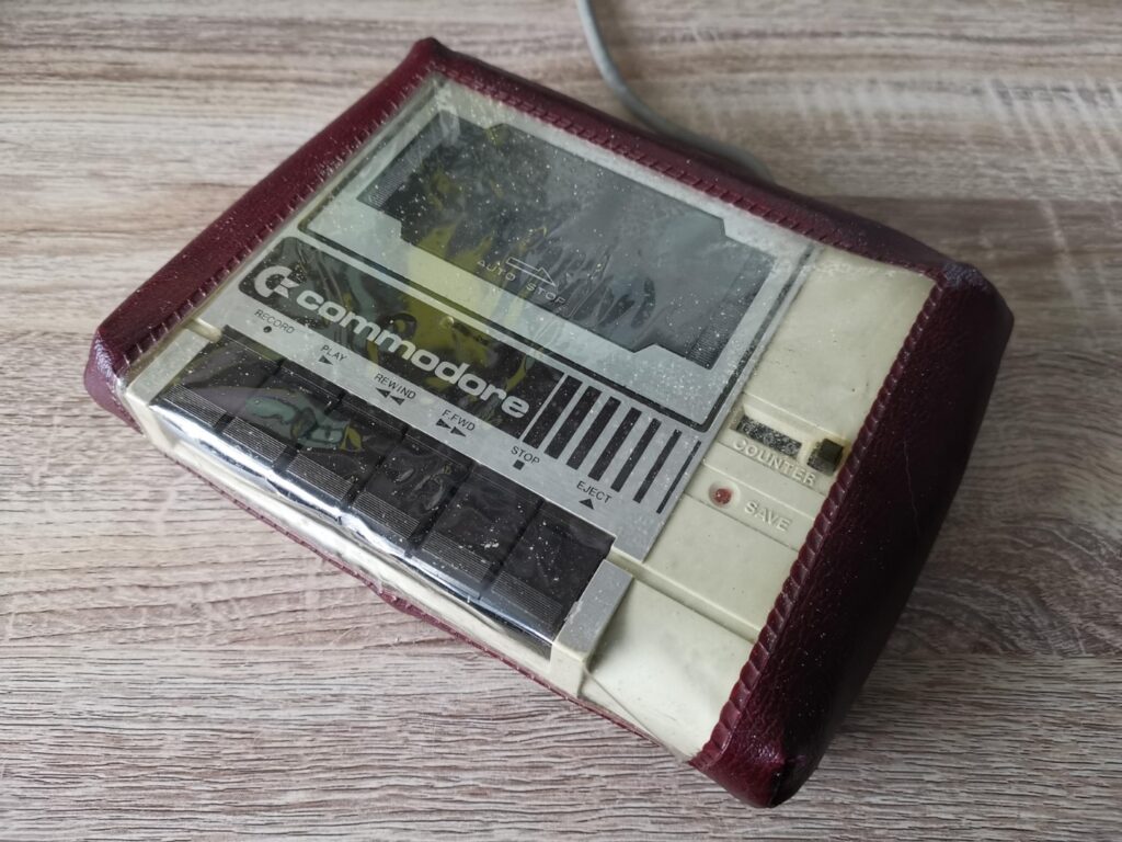
A modern, stylish datasette dust cover is something I’ve been after for quite some time. I do still have the burgundy leatherette one that my parents bought me back in the 80’s but it is seriously hideous now. In fact who am I kidding? It was probably hideous even back then but being just a kid I didn’t know any better!


Datasette Dust Cover

Was this even cool back in the 80’s? Regardless, the time has come for it to go…


Why do I need a dust cover anyway?

Most of my retro computers have very nice, custom made transparent perspex covers. They offer great protection from dust and scratches whilst also still allowing me to see my beloved machines.

We have two cats in our household that think everything is fair game to sleep on. Besides keeping dust at bay they are great at keeping cat hairs out of keyboards and everywhere else cat hairs shouldn’t be. I buy all my dustcovers from a company called Retronics based in Poland.


This slideshow requires JavaScript.


Anyway back in February I spotted this teaser on their Facebook page which clearly showed they were  working on a dust cover for the Commodore Datasette. I duly made a mental note to keep checking back to see when it was available. A few weeks ago I checked again and noticed that it was finally available so I went ahead and bought one from their eBay shop.

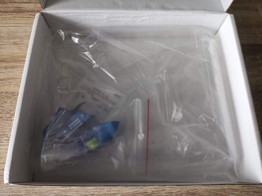
Inside the box.


Sweeties!


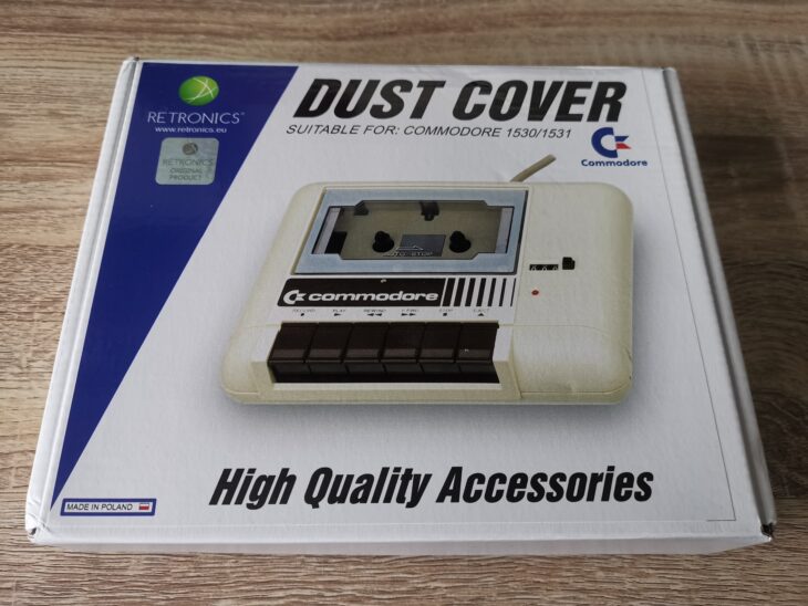
It arrived yesterday so here’s a quick look at it. It was packed inside a very attractive box displaying a nice photo of a 1530 Datasette on the cover. Opening it up revealed the cover tucked into a plastic bag along with some delicious freebie Polish sweets. (Every order I have ever received from them has contained these) 🙂


Datasette Dust Cover

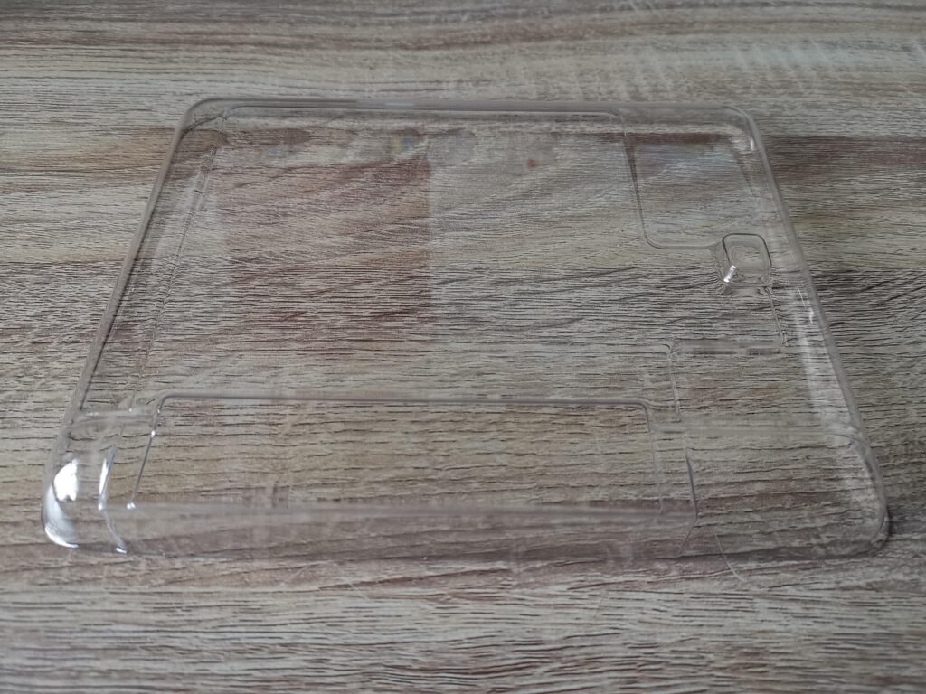
Naked Dust Cover.


With it being transparent it’s quite a tricky thing to photograph!


Datasette dust cover

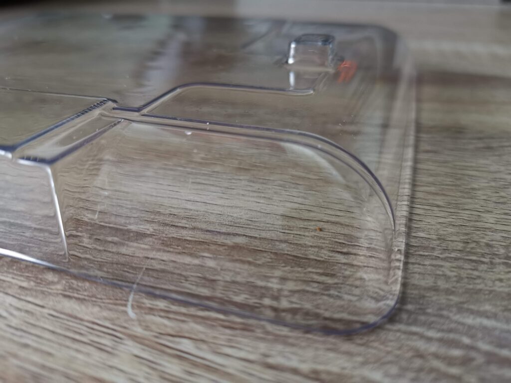
The unmistakable bump for the counter reset button.


Impressions & Photos

There isn’t really a great deal you can say about a dust cover. This product does exactly what it says on the box. It’s very well made and the dimensions are just right so that it rests securely on top of the datasette without sliding around. It has all the lumps, bumps and ridges exactly where they need to be to fit correctly and look the part.

They say a picture speaks a thousand words, so here’s a bunch of photos of the dust cover doing its thing. From certain angles it almost looks like there’s no cover on at all, which for me, is exactly how I like it.


This slideshow requires JavaScript.


The bottom line? If you own a 1530/1531/C2N/Datasette and you are in the market for a stylish dust cover then I don’t think you will find anything better than this.

How to Build Your Own Cassette Tape Winder

I’ve always wanted a cassette tape winder so when I stumbled across this plan on Thingiverse I thought it would make a great little project for my 3D printer. Sure I could search on eBay and maybe pick up an old one but where’s the fun in that? So here’s a little guide to how I built my own cassette tape winder.

Computer Stuff

First off I had to download the zipped STL files from the Thingiverse site. (STL files contain 3D CAD objects that you can print).

Each component has it’s own STL file and there were 10 of them for this project. You can see them all listed in the folder screenshot below.


These are the components that you need to 3D print.


You cannot print STL files directly so I use a piece of free software called Cura to work with them. This software allows you to see the STL files as an interactive 3D model. It also processes STL files by ‘slicing’ them into layers that can then be saved as GCODE files and printed on a 3D printer. If you’ve never 3D printed something this might all sound very complicated but it really isn’t.


Build Your Own Cassette Tape Winder

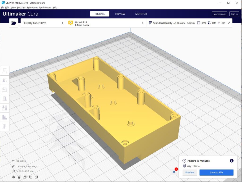
Winder case as viewed within Cura software.


The image above shows the main case for the winder in Cura. I have already sliced it and it shows an estimate of how long it will take to print, over 7 hours in this case. 3D printing is not a fast process!


Beginning the 3D Printing


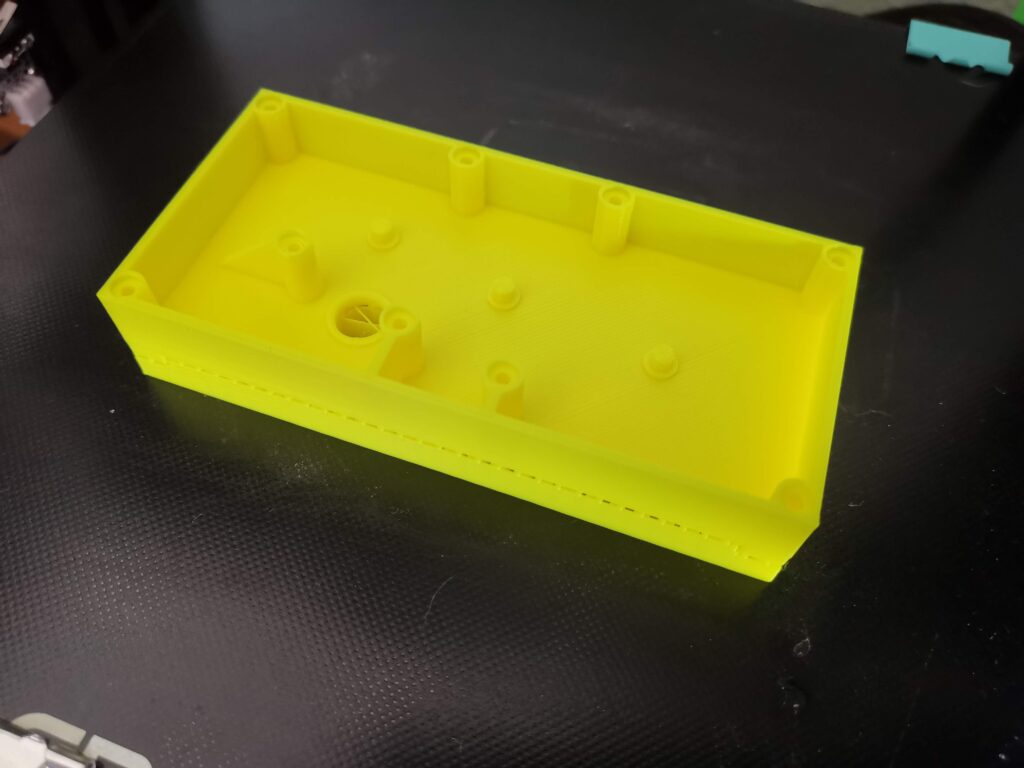
Freshly printed winder case.


Above you can see the finished case print… but there’s some extra support material that will need to be removed from underneath it. 3D printers can’t print (over long distances at any rate) in thin air so they need to create a kind of scaffolding system (supports) in order to do so.


Removing the 3D printed support material.


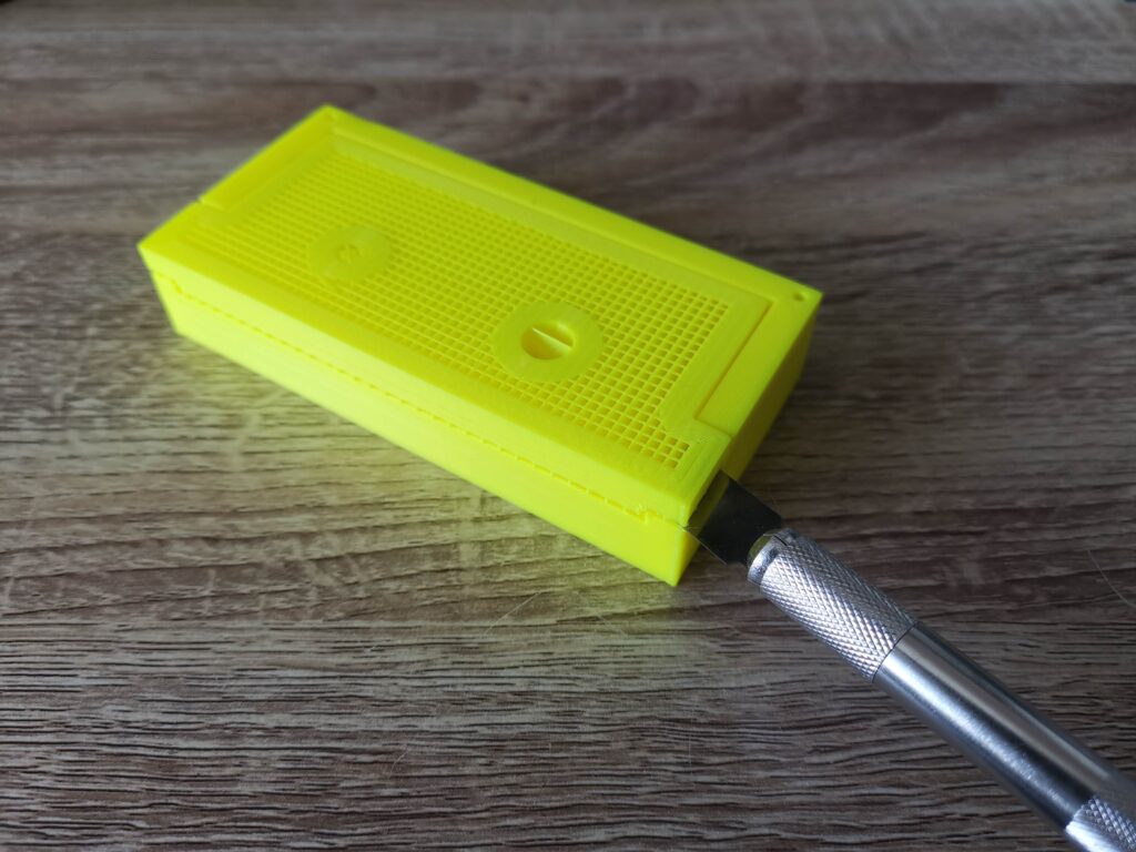
Support material is designed to break away easily from the main print. In the above photo I used a sharp craft knife to break away the support material. It only took a couple of slices and then I was able to get my fingernail under it and simply pull it away in one piece.


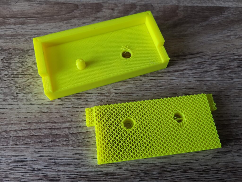
View showing the support material removed.


With the support material removed you can now see the winder start to take shape. In the above photo you can see the latticed support material too. It’s made this way to minimise plastic wastage and also allow it to be broken away easily. The fewer points of contact it has with the main build, the easier it is to break off.


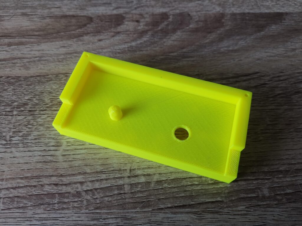
Here the few little pieces of support material that were clinging on have been removed with a craft knife.


In the above photo I have cleared away the few little straggly bits of plastic left by the supports with my craft knife.


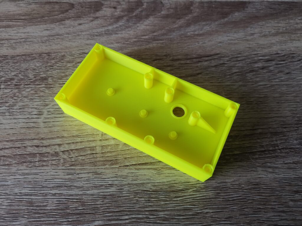
This is the case viewed from the other side.


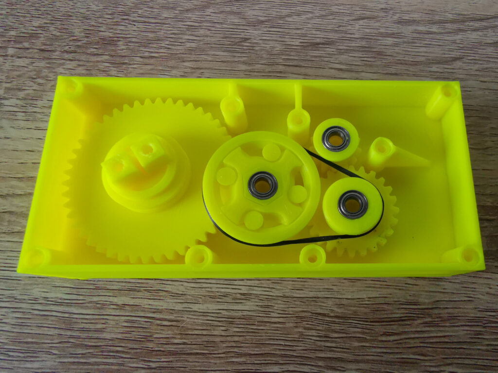
This is what the inside of the winder case looks like. There are 8 posts to support the case screws, a hole for the winder spool and 3 protrusions where the gears will sit.


Gathering the parts together


Build Your Own Cassette Tape Winder

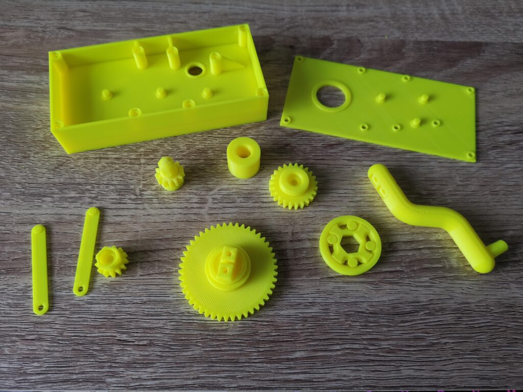
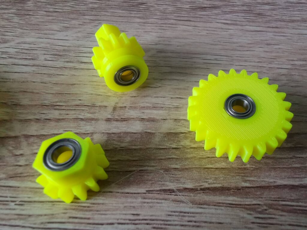
All the 3D printed components ready for assembly.


This photo shows all the parts of the winder fully printed a few days later. The instructions advise printing the cogs on rafts because they can be difficult to remove from the print bed. However I didn’t bother… I have glass bed and things pop off very easily once it cools down. It also means the finished prints are smooth and clean but of course YMMV. I did use supports for everything where the instructions recommended to do so and carefully removed them after printing.


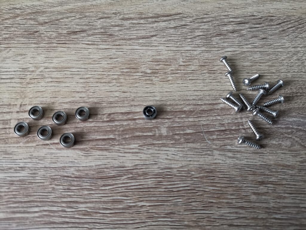
The bearings and screws needed.


What you will need

In addition to the 3D printed parts a few bits of hardware are also required. Some bearings, screws and a rubber belt. Here’s a rundown:

  • 6x  4x8x3 miniature ball bearings for the gear wheels – I used these.
  • 1x  3x8x3 miniature ball bearing (for the winder knob) – I used these.
  • 14x  3x12mm pan head self-tapping screws – I used these.
  • A 1mm square rubber belt approximately 55mm in diameter.
  • Philips screwdriver.
  • Craft Knife.
  • Side cutters (to help remove support material if necessary).
  • Silicone Grease (optional but recommended).
  • 3D printer!


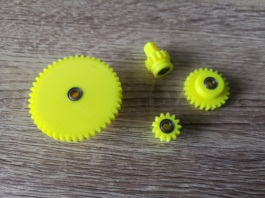
Gears with bearings fitted.


The next step was to fit the 6 bearings into the gear wheels. The two pulley cogs are fitted with two bearings, one each side whilst the driving gear and spool take just one.


Gears with bearings fitted.


The bearings were a snug fit but I didn’t have to force them in at all. Once fitted they remained in place by friction alone so there was no need to glue them in.


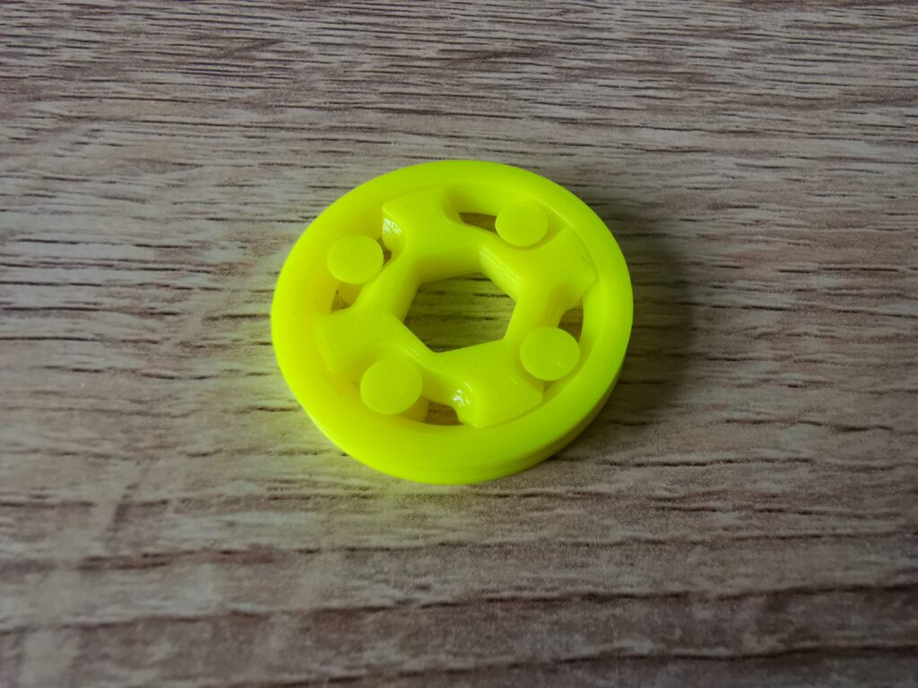
One-way clutch.


The winder incorporates an ingenious little one-way clutch mechanism that will only rotate in one direction. The benefit of this is it prevents you from accidentally winding a tape in the wrong direction causing it to unspool inside the case. Impressively it prints in situ too – there are 6 moving parts which are all printed as one complete mechanism together.


Putting it all Together


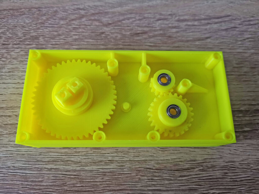
Start with these gears first.


Next came the exciting part – putting it all together. The driving gear, both pulley’s and spool went in first, making sure the bearings all seated correctly on the pegs.


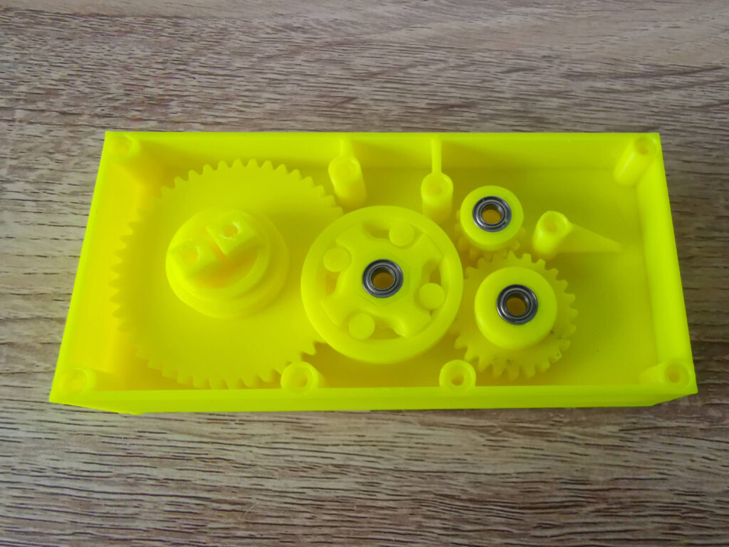
Then add these. Note that pulley 1 and the clutch have already been assembled in this photo.


Next to go in was the one-way clutch which fitted onto the hexagonal shaft of pulley 1.  It can fit either way around but needs to installed so that it ‘sticks’ when turned anti-clockwise but free-wheels clockwise. The instructions said to glue this in position but I didn’t bother as its going nowhere once the lid is attached.


Build Your Own Cassette Tape Winder

The rubber belt is added last.


The belt went in next and simply needed stretching around the clutch and pulley 2. There was a fair amount of tension here with the clutch being pulled over to one side, however once the lid goes on and the pegs slot into the bearing top and bottom, it sorts itself out.


A minor issue…

I did have one issue at this point when putting everything together. There was too much friction with the spool and it wasn’t turning freely. I tried shaving/filing plastic from the cog teeth, adding a drop of oil to the bearing and adding a little silicone grease to the teeth but none of this really helped.

In the end I reprinted the part scaled down slightly to 98% which allowed the spool to spin freely. I also had to enlarge the bearing recess slightly with a Dremel so the bearing would still fit inside. Possibly if I’d persevered a little longer with the file I could have got the original part to work. However given how everything else fits together perfectly I figured the part needed re-designing slightly for a better fit. Regardless, I’m happy with my fix and how it now operates.

Before I screwed the back cover on I also added a tiny bit of silicone grease to the other gear wheels just to help keep them lubricated.


The Finished Winder


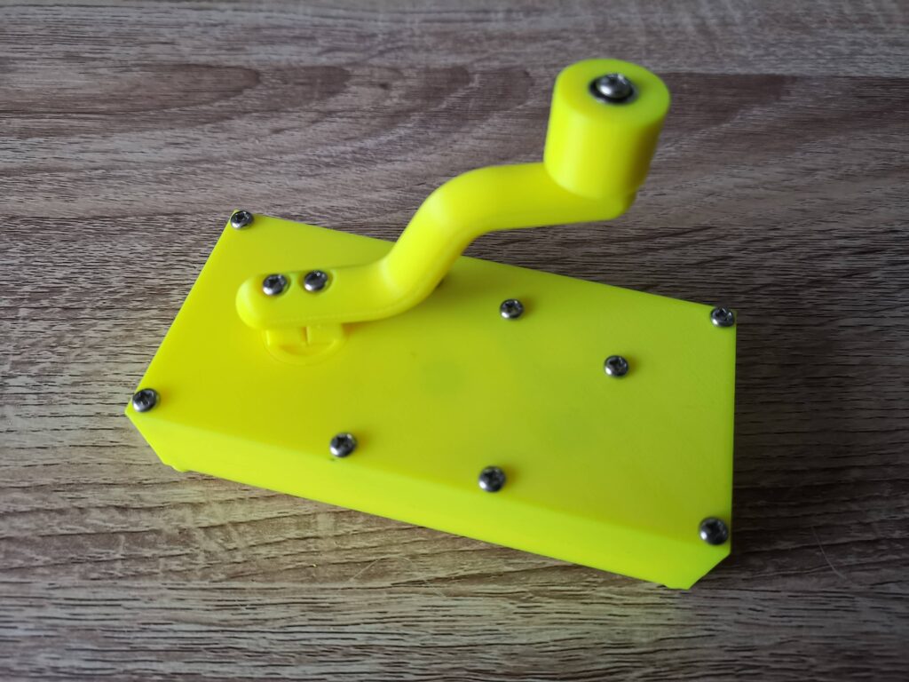
View of the back of the assembled winder.


Here’s the winder with the back screwed on and the handle and knob attached.  The knob also has a bearing inserted into it so that when it’s screwed to the handle it will still spin freely.

I had no issues screwing things together but the instructions did advise caution in case the plastic splits and suggested drilling out the holes further as a precaution. Again I didn’t bother as I felt my screws were a good fit for the holes but again YMMV.


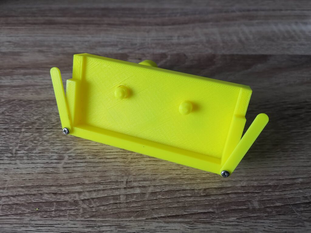
Front of Winder with retaining clips attached.


The two retainer clips attached to the front of the case using a couple more screws. The dimples are positioned such that they face the back of the winder.


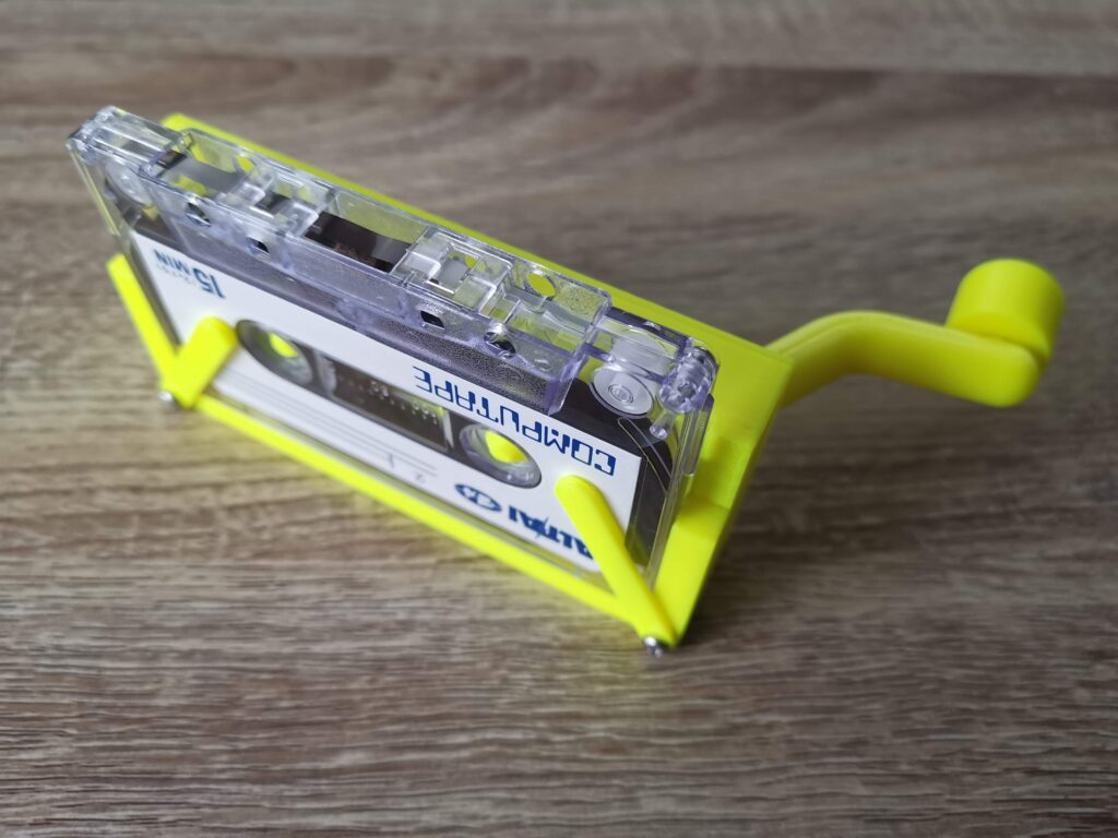
Tape held captive by retaining clips.


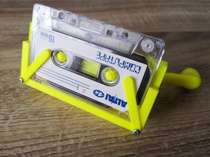
The screws need to be tightened just enough so that the clips can move with a little force but remain in any position. These are used to hold cassette tapes securely in place whilst winding.


Build Your Own Cassette Tape Winder

View of the winder looking down.


Video of winder in use

And here’s the finished winder. I have to say it works extremely well and will be a great help in minimising wear and tear to my various C2N Datasette’s, Walkman’s and tape decks. It’s fast too, I managed to rewind a C90 tape in around 30 seconds. The use of a belt helps to ensure that when reaching the end of a tape, any excess force results in the belt slipping rather than damaging the tape.


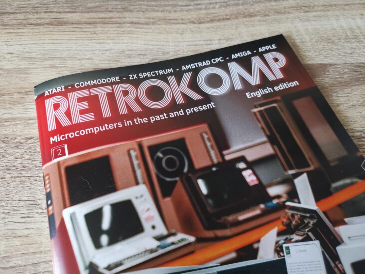
Latest Retrokomp Issue 2 is now out

Retrokomp Issue 2

Just received my copy of Retrokomp Issue 2, the multi-format retro magazine.


Retrokomp Issue 2

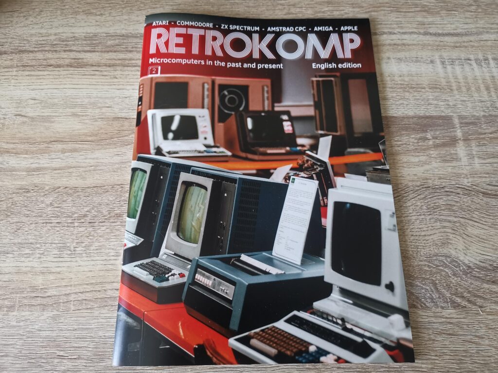
Retrokomp Issue 2 Cover


Once again there is plenty of content with a hefty count of 72 thick glossy pages and over a third of them devoted to Commodore machines. If you are interested in other machines besides Commodore then there’s even more on offer with the like of ZX Spectrum, Atari, Amstrad, Apple 2 and even old IBM PC’s covered.


Retrokomp Issue 2

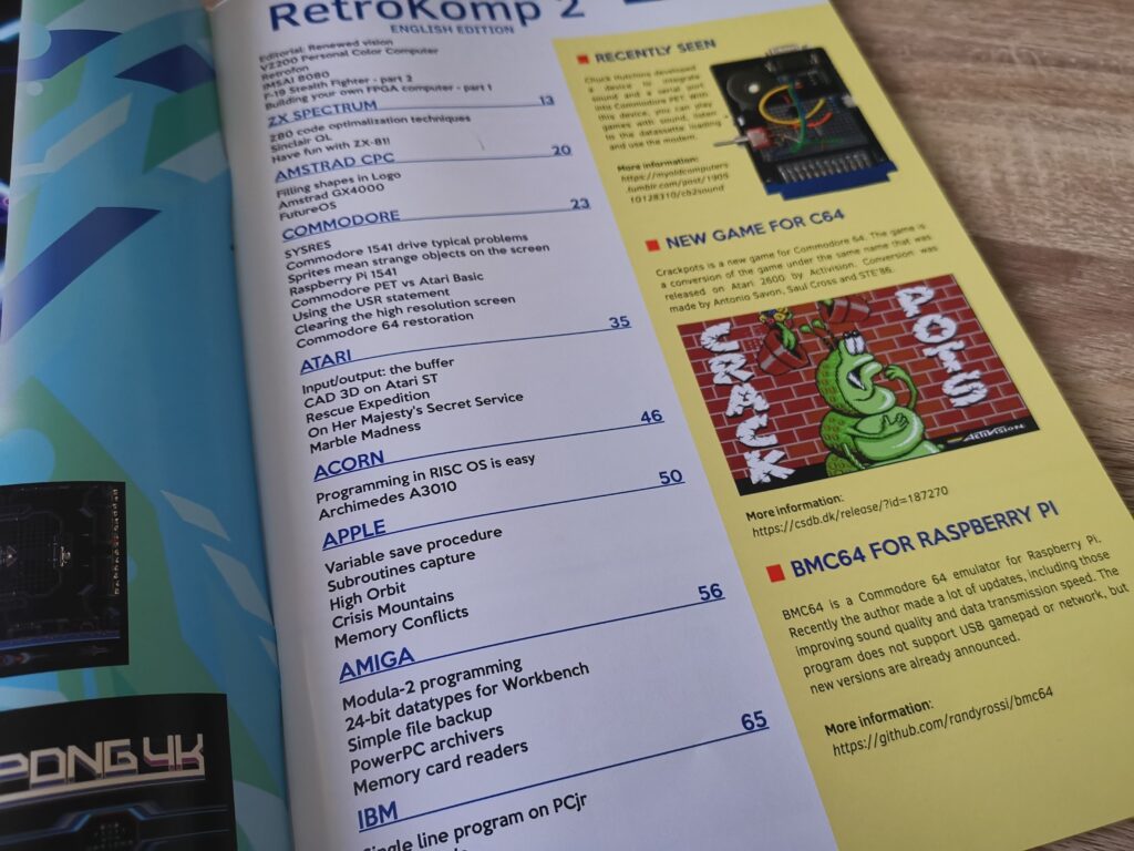
Contents of this issue


Here’s a few highlights of this issues contents.


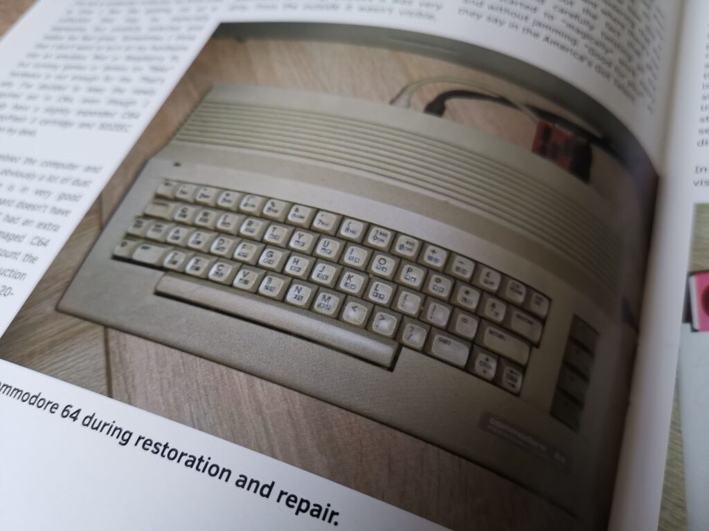
C64 Restoration project.


Retrokomp Issue 2

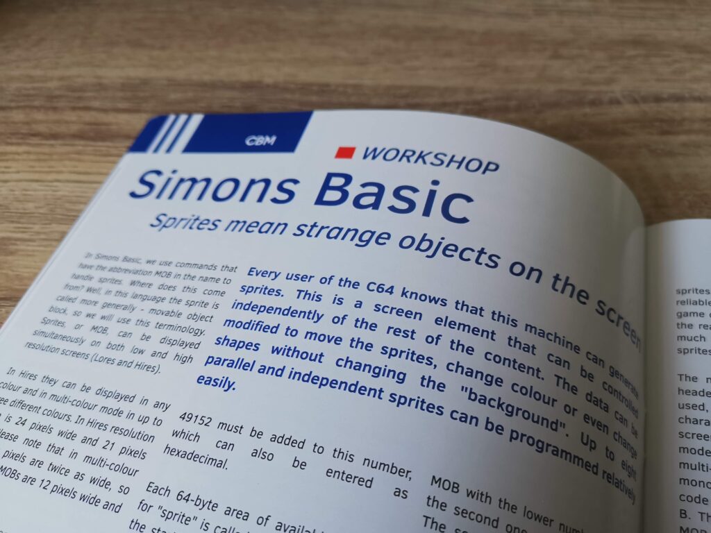
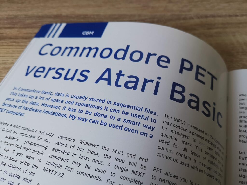
A look at Simon’s BASIC on the C64.


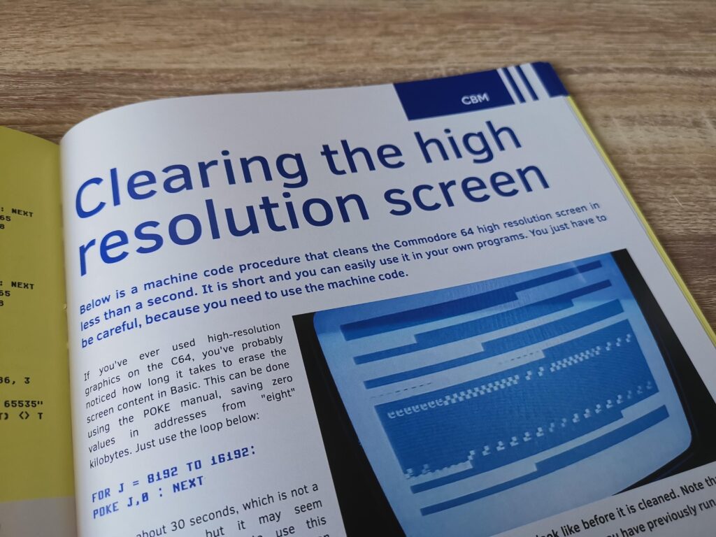
How to clear the Hi-Res screen on a C64.


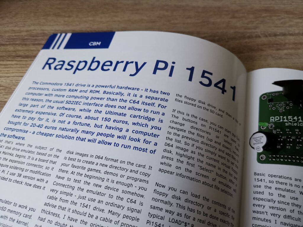
A look at the Pi1541 disk drive emulator.


Retrokomp Issue 2

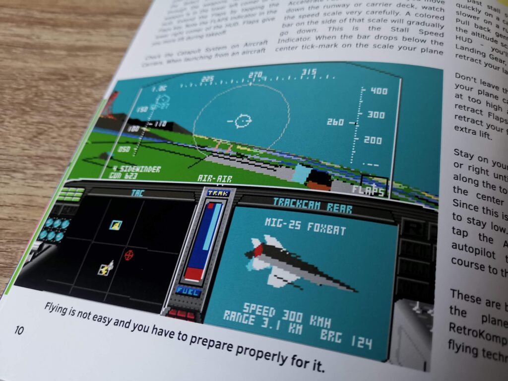
Part two of the Project Stealth Fighter article.


Comparison between Atari and CBM BASIC.


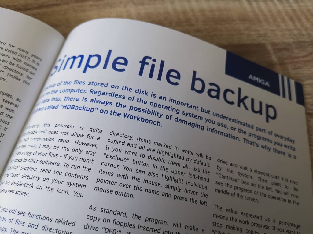
A look at file backup on the Amiga.


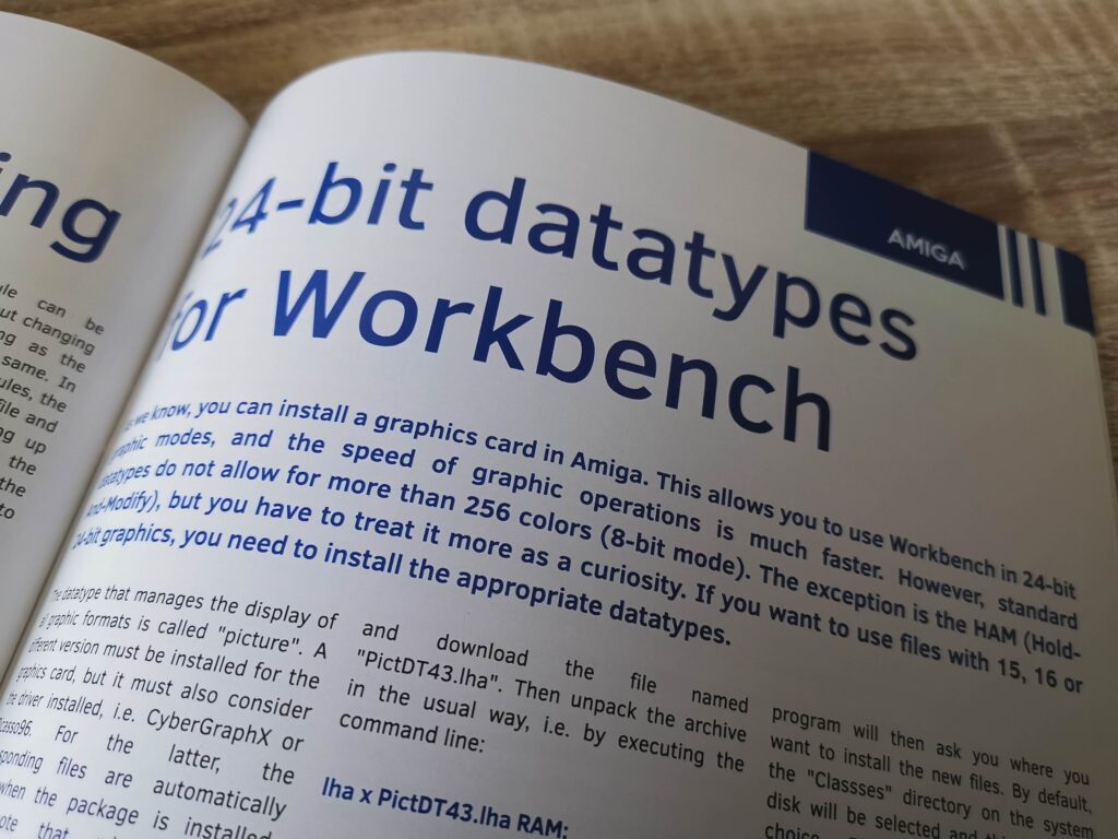
24-bit datatypes on the Amiga.


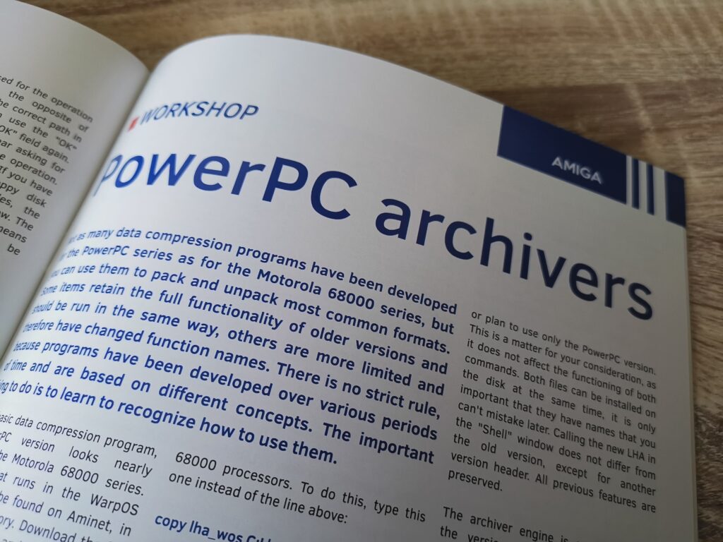
A look at archiving software for PowerPC equipped Amiga’s.


Card readers on the Amiga.


Amiga Modula-2 Programming.


A quick run-down of the Commodore-centric articles in Retrokomp Issue 2:

  • Sysres
  • Commodore 1541 Drive – Typical Problems
  • Simon’s BASIC – Sprites mean strange objects on the screen
  • Raspberry Pi 1541
  • Commodore PET vs Atari BASIC
  • Using the USR statement
  • Clearing the high resolution screen
  • Commodore 64 Restoration
  • Modula-2 Programming
  • 24-Bit datatypes for Workbench
  • Simple file backup
  • Memory card readers

If you’ve never come across Retrokomp magazine before you might like to read through my preview of the first issue here and the second, here.

Alternatively if you’d like to purchase a copy of Retrokomp Issue 2 for yourself then visit the publishers website here and show your support.

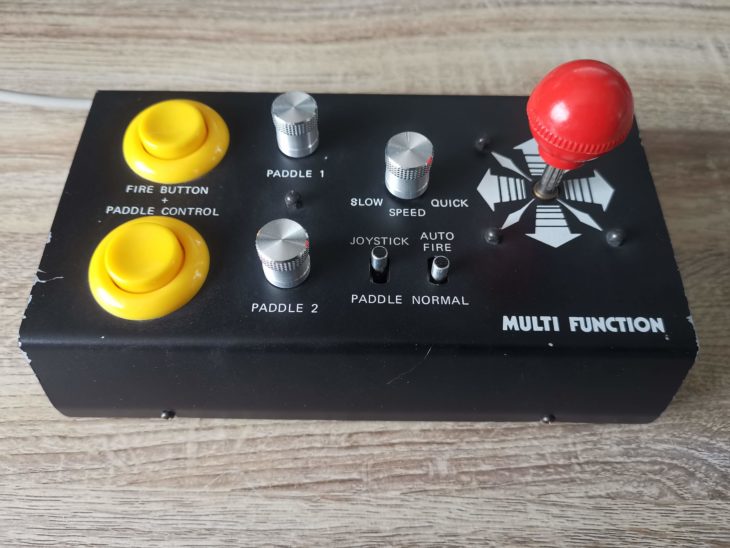
Hedaka Multi-Function HED-1 Joystick

Hedaka Joystick

While I was looking for a new gamepad for my Commodore 64 a while back I stumbled across this bad boy. It’s called the ‘Hedaka Multi-Function HED-1’ joystick and I spotted it on the German eBay site and imported it to the UK. All in with postage I think it cost me around £40.

Using the interactive 3D display immediately below you can take a look at the box it came in. Just click inside the box and then when the hand icon appears drag to rotate and zoom in and out.

I honestly don’t know too much about the origins of this device – I simply bought it because it looked interesting. From the German language used on the box it appears to have been made for the German market. However all the text on the device itself is in English which seems a little odd. It’s worked out great for me though as I know instantly what everything should do!


Hedaka Multi-Function HED-1 Joystick Specs

Using my amazing multi-lingual abilities Google translate I was able to glean the following information from the specifications listed on the box:

  • Control knob for computer games, suitable for many computers, Atari all types, Commodore VIC20, C64, 128 and C16 & Plus/4 with adaptor.
  • Additionally 2 integrated paddles
  • Particularly sensitive control by micro-switch
  • Auto-fire infinitely adjustable
  • Extra large fire-buttons
  • Stable metal housing
  • Practical suction feet for safe stand
  • Extra long connection cable

Basically this device looked to have been aiming to be the only controller you would ever need to use with your computer!


This slideshow requires JavaScript.


Construction

This thing is built like a tank with the entire case being constructed from 1mm thick powder coated steel. The base measures 20cm x 12cm and the height to the top of the joystick is 10cm. A very generous 3m long cable is provided which means you can use this device from pretty much anywhere in the room.


Hedaka Joystick

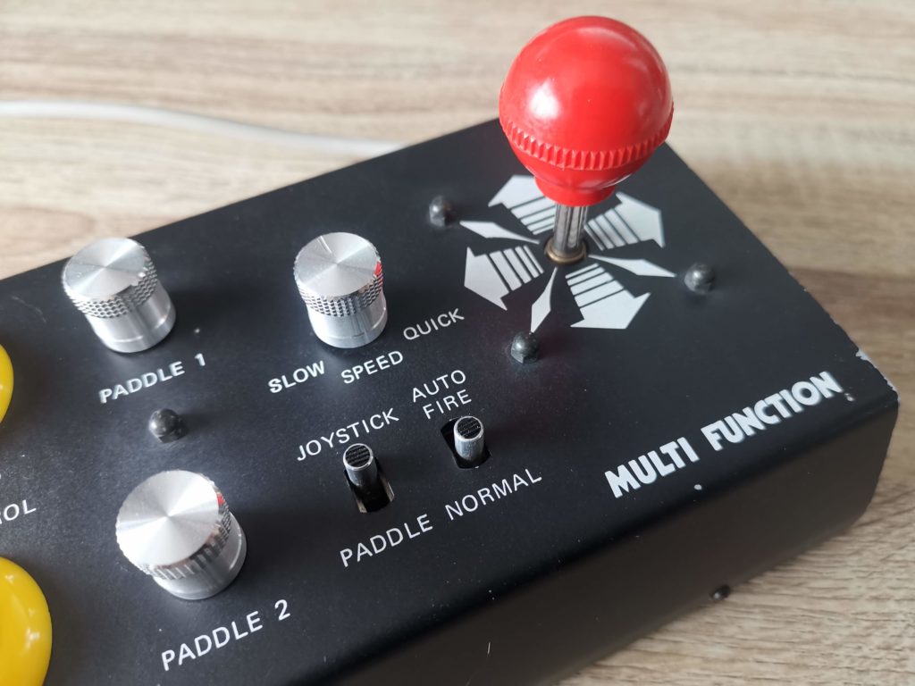
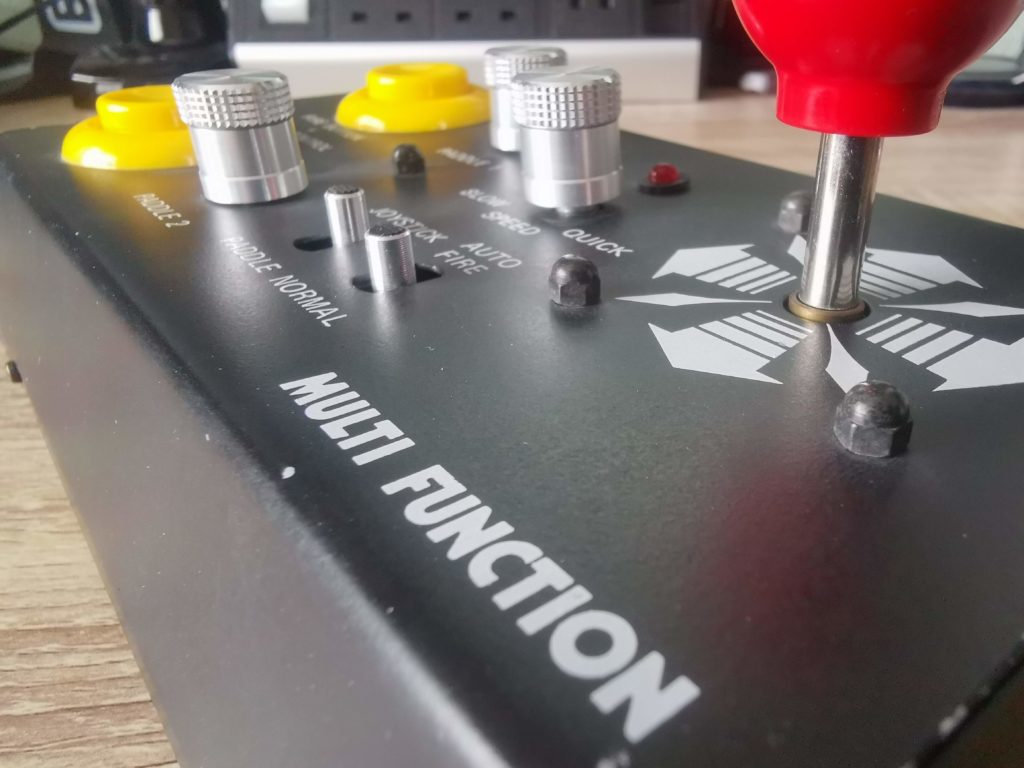
Closer view of the joystick controls.


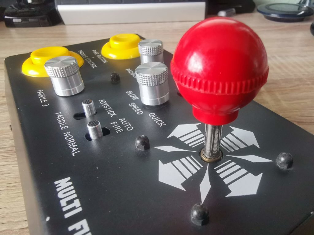
The stick itself is very comfortable in use and the micro-switches ensure you get a nice tactile ‘click’ as you move it around. The oversized fire buttons provide similarly satisfying feedback when pressed. The joystick requires only light pressure to operate and about 5mm deflection from centre to register a click.


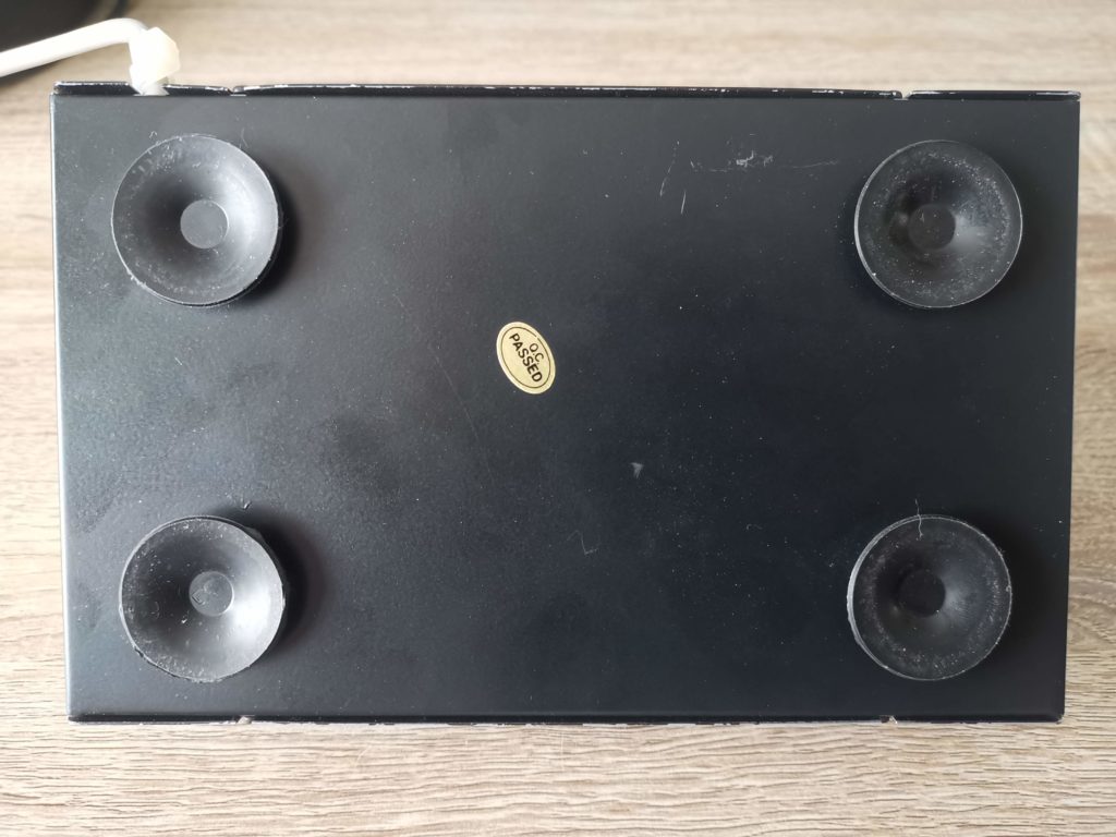
View of the base showing the four sucker feet.


On the underside of the joystick are 4 large rubber suckers that allow you to stick the base to a desk or table. These work really well and on a completely smooth surface possibly a little too well. When I placed the joystick down on a glass coffee table I really struggled to get it off!

When firmly affixed to a surface it gives a great arcade-like experience. I tried using it on my knee but it quickly became uncomfortable. However sticking it onto a place mat first and then on my knee offered a comfortable compromise.


Hedaka Joystick

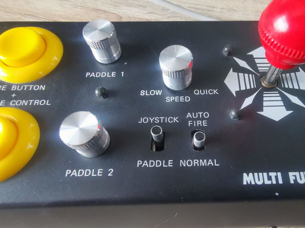
In this view you can see the red LED just to the right of the auto-fire speed control knob. This visually displays the rate of fire.


Auto-Fire

For shoot-em-ups you can opt to turn on auto-fire mode using the toggle switch. Once this is engaged there is a speed selector knob which can be rotated to fine tune the rate of fire. This is completely analogue and the knob rotates through 270′ so you really can set it to anything you desire. There is a red LED above the speed control knob that lights each time the fire button is activated providing instant visual feedback of the rate of fire. The auto-fire only engages whilst the fire button is held down too which makes perfect sense.


Hedaka Joystick

Close-up of the joystick itself.


Paddles

The real ace up its sleeve for me though is the inclusion of paddle controls. This means if I fancy a quick game of Panic Analogue (easily my favourite paddle game) I no longer need to dig out my Atari Paddles.


Hedaka Joystick

Close-up of the paddle controls.


Both paddles are implemented and of course each has its own fire button. The button for paddle 2 is activated by selecting another toggle switch. The paddle knobs do take a little getting used to as they are much smaller than a typical paddle wheel (1cm diameter v 6cm). However they work effectively and allow very smooth and precise movement.


A Look inside

Just out of curiosity I decided to open up the case and have a peek inside. There are four philips screws along the lower edge of the base keeping the cover firmly attached. These screws fit into four little slots cut into the sides of the cover so they only need to be loosened a few turns and the cover will slide up and off.


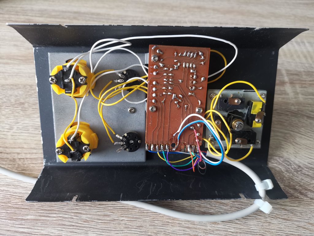
View of the inside with all the electronics attached to the top cover.


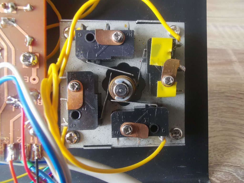
Close-up of the joystick micro-switches.


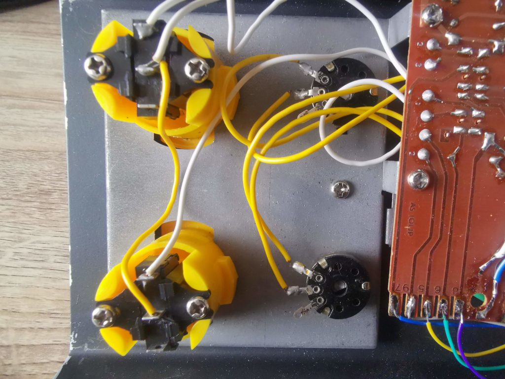
This is a close-up of the two micro-switch fire buttons (left) and the Paddle potentiometers (right).


Verdict

This is a terrific joystick and I’m so glad I took a chance and bought it. The auto-fire feature is superb, probably the best implementation I have seen. Furthermore, the design of the joystick with its large base, oversized fire buttons and limpet-like suckers means it offers a very arcade like experience. Playing the classic Gorf or the much more recent Galencia with this joystick is a real pleasure. When I want to play the odd paddle game, not having to swap controllers to do so is incredibly convenient. Definitely a recommended pickup if you see one up for sale.

Eight Bit Magazine Issue #8 Out Now

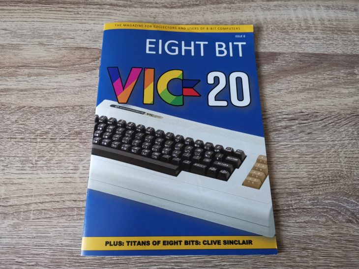
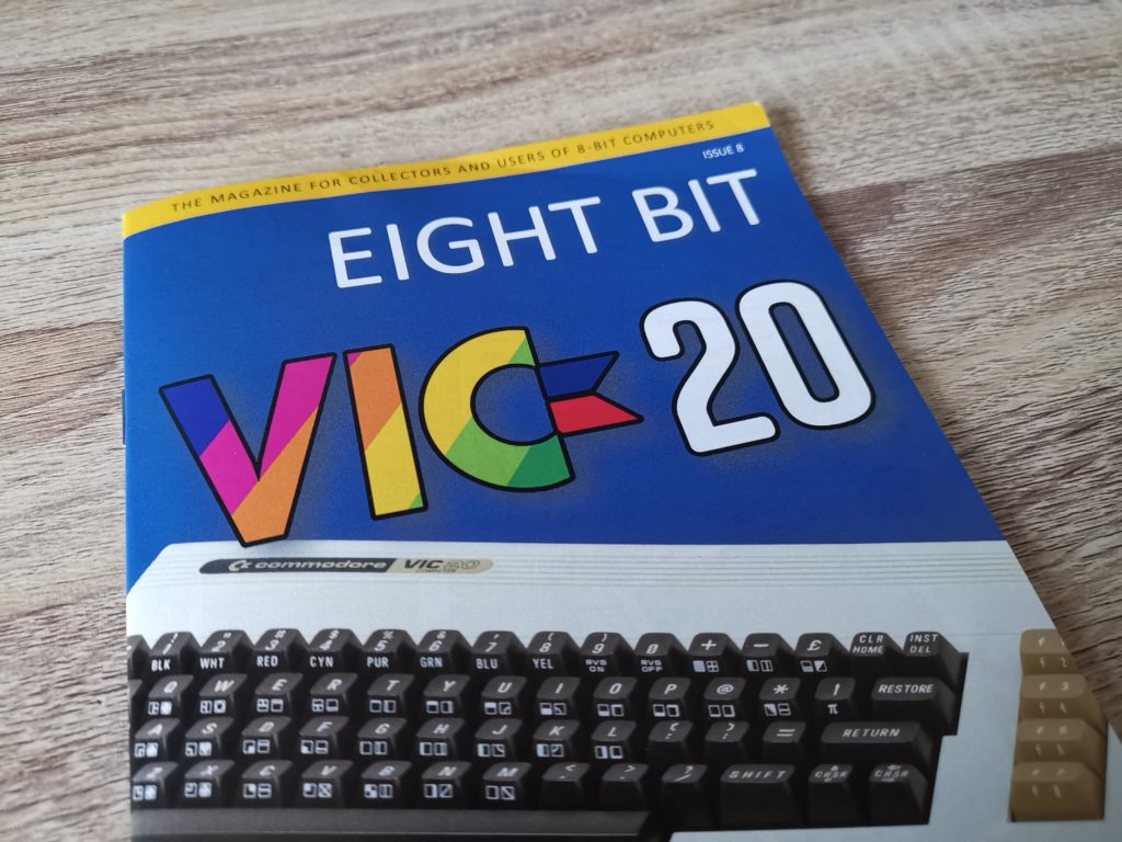
Eight Bit Magazine Issue #8

I have to say the latest issue of Eight Bit magazine (issue #8) really caught my eye. There’s a VIC20 featured prominently on the front cover, a machine I have a real soft spot for as it was the first computer I ever owned. Most magazines tend to focus on its more powerful and popular sibling (the C64) so any coverage is more than welcome.


Eight Bit Magazine Issue #8

Cover featuring the Commodore VIC20


Inside there’s an interesting ten page ‘Collectors Guide to the VIC20’. It starts with a brief history of the VIC20 including that famous advert with Captain Kirk. It also looks at the machines hardware, the software available both back in the day and a few of the new titles released recently. It’s a good read for sure but it’s actually quite a short article and left me wanting more.


This slideshow requires JavaScript.


Also in the issue is a really in-depth look at 8-bit baseball games. Unfortunately I have zero interest in baseball so I moved swiftly onto the next article which looks at IRATA.ONLINE. I must confess I’d never heard of this until now but it looks very interesting indeed and worthy of more investigation.

There’s also a look at ‘Retro Virtual Machine’ (a Spectrum & Amstrad CPC emulator) and a lengthy feature looking at the creations of Sir Clive Sinclair. To round off this issue there’s a couple of game reviews: Shockway Rider (which is available for the C64) and a Text Adventure called Tower of Despair for the Spectrum.

All in all the magazine offers a good read, though because it doesn’t focus on any single machine YMMV.

If this post has piqued your interest and you’d like to buy a copy then take a look at the Eight Bit Magazine website.


VS-7000 Joystick Review

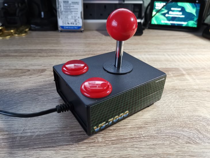
VS-7000 Joystick

I recently picked up a super little arcade joystick off eBay for my Commodore machines. It’s brand new and made by this seller on eBay. He’s calling it the ‘VS-7000’. I’m really impressed with it so thought I’d share my thoughts.


This slideshow requires JavaScript.


VS-7000 Joystick Construction

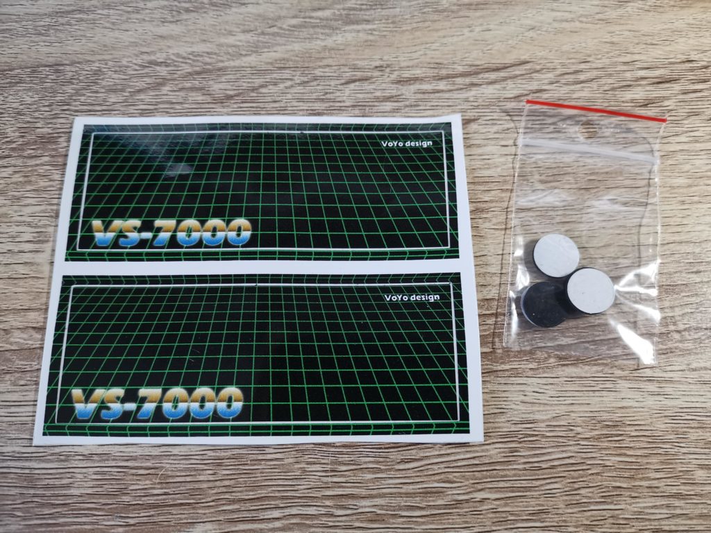
As standard it comes with a plain black plastic base with four sucker feet. However there’s a couple of retro styled vinyl VS-7000 stickers supplied in the box. These can be attached to the sides of the base if you want to jazz it up a little more. Additionally, if suckers aren’t your thing then they can be replaced by the included set of 4 rubber feet.

The seller also offers the same joystick in a couple of other colours. There’s one with a white base and another black one but with wood effect panels, presumably for people that want to use it with Atari systems. Sadly at the time of writing this he’s got no stock left of any variant but hopefully he’ll make some more soon.


VS-7000 Stickers and Rubber feet

The supplied stickers to go on either side of the base and a set of 4 rubber feet.


Both the buttons and stick are micro-switched and this makes for a really satisfying ‘click’ when pressed. In use I was never unsure whether a button had been pressed that’s for sure. The joystick unit itself is based on the Sanwa mechanism which is designed for arcade game cabinets. The shaft is made of metal with a nice chrome finish and it all feels reassuringly sturdy in use.

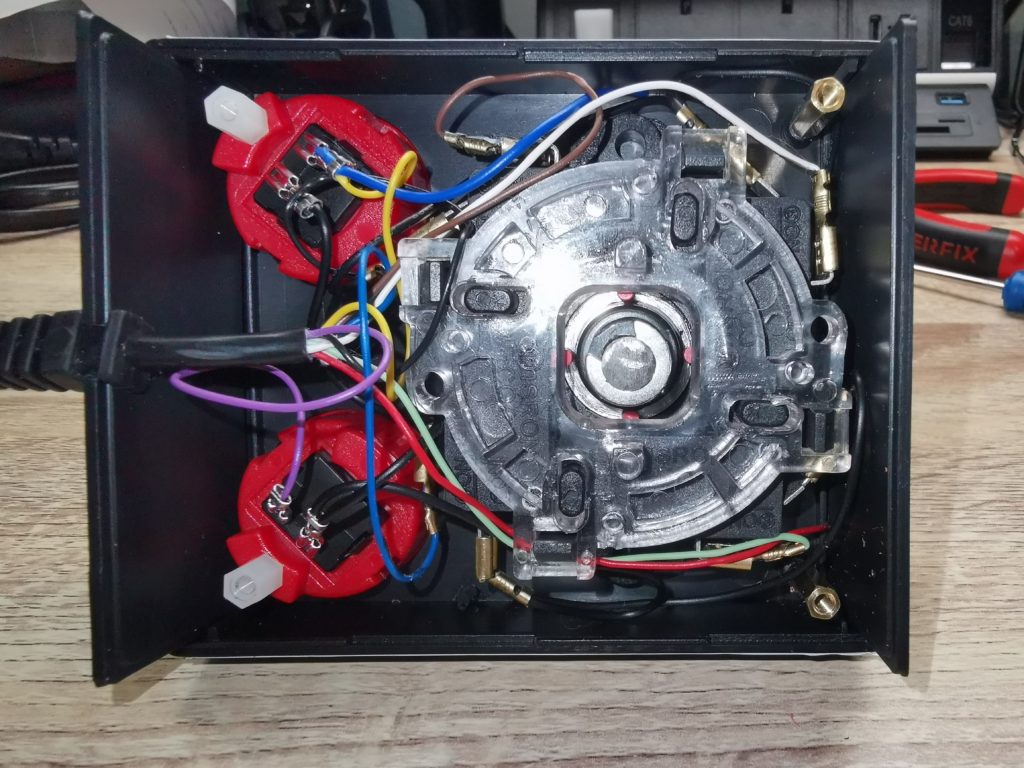
The joystick is available with either two ‘A’ buttons or an ‘A’ and ‘B’ button configuration (on request). It is straightforward enough to change from ‘AA’ to ‘AB’ yourself too. Unfortunately the A & B configuration of this stick is NOT compatible with 2 button capable C64 games like Super Mario Bros and Chase HQ 2. The C64 just doesn’t see the extra button at all.


VS-7000 Joystick

Here’s what the inside of the joystick looks like


Verdict

I have to say that this little joystick has really exceeded my expectations. It requires very little lateral force to move the stick around so it makes extended play sessions much more comfortable. I also found it enabled me to move around games more accurately or pull off those different moves in IK+ more easily. Puzzle games such as Vegetables Deluxe and Milly & Mollie suddenly became far more relaxing to play too.

I can’t overstate how much I love the stick movement on this thing. Selecting a direction only requires a gentle nudge which is immediately rewarded with a satisfying click. I can guide it in the direction I want using just my forefinger and thumb instead of needing to clamp my whole hand around it. Consequently, playing for hours no longer results in getting cramp in my right hand like I do with the other sticks (especially the Suncom). I should point out that this may well be an age related preference. I loved the ZipStick when I was a kid but fifty year old me? Not so much.

The VS-7000 joystick does have one shortcoming though… the base is quite bulky and angular so is not the most comfortable thing to hold for extended periods of time. However I suppose that’s to be expected from a homebrew project like this. The joysticks of yesteryear were manufactured in large numbers and had custom, injection moulded bases, not something you can easily replicate on a small scale. Having said that this didn’t prove to be much of an issue for me as I use it mostly either resting on my knee or affixed to my desk with the suckers.


This slideshow requires JavaScript.


Commodore 1501 Power Monitor MkII Review

Commodore Power Monitor

Whilst I was idly scrolling through eBay one evening a rather cool looking gadget caught my eye. The device in question is the ‘Commodore 1501 Power Monitor MkII’ to give it its full moniker. I’m a sucker for anything with coloured LED’s, VU meters, flashing lights, knobs switches etc. Basically anything flashy or mechanical in nature. This little device features both multiple colour digital displays and a big red nuclear launch button – how could I resist?


Commodore 1501 Power Monitor

Here’s what came in the box, the Power Monitor itself and a power cable.


The seller is in Australia so delivery to the UK took a few weeks. It arrived well packaged in a small cardboard box. Opening the box revealed the Power Monitor itself together with a short power lead. The device is constructed entirely from plastic but has a textured finish that makes it look like it’s made of metal. The Commodore 1501 label is very convincing and makes it look like a real commodore product (although obviously it isn’t).


Commodore Power Monitor

A big red ‘reset’ button screaming to be pushed!


Flip the box over and there’s even an official looking serial number label on the bottom. The overall presentation on this is top notch and really made me feel like I was back in the 80’s and had just purchased an ‘proper’ Commodore product.


Commodore Power Monitor

Serial number sticker.


So what exactly is it then?

This device does exactly what the label says – it monitors the power output of your Commodore PSU. In simple terms it’s basically a voltmeter and ammeter rolled into one. It is able to measure both the 5v DC and 9V AC PSU outputs and also measure the current being drawn by the computer.

In an ideal world your PSU should be outputting voltages as close as possible to the 5v and 9V levels that your Commodore needs. However this is often not the case, especially with old Commodore PSU’s. There are plenty of horror stories online about C64’s being fried by PSU’s that output higher voltages. It is supposed to work on the Commodore 128 and Plus/4 in addition to the VIC20 and C64 but as I don’t own either of those systems I can’t confirm this.


Commodore 1501 Power DIN socket

One of the two DIN sockets for attaching the power leads.


The 5V supply is used to power most of the chips on the mainboard and is the most sensitive to increased voltages. The unregulated 9V supply is used to power any attached C2N datasette, the user port and the SID chip amongst other things.

The seller claims accuracy is within +/- 0.1V for the DC meter and +/- 0.3V for the AC meter.


Interpreting the readings

The instruction booklet (available digitally) gives a handy guide to interpreting the voltage displays:

Voltage RangeDescription
4.95 - 5.1V Power supply functions normally.
5.1 - 5.2VMinor concern, measure the power supply
more often.
5.2 - 5.5VThe power supply is failing. Your Commodore
64 will not fail right away, but it is an
unhealthy situation. Replacement or repair of
the power supply is recommended.
5.5 - 6VYour Commodore 64 is in danger.
>6V In most situations where a Commodore 64
got killed by its power supply, the voltage had
risen above 6V. Usually the RAM memory
gets damaged first.

For some reason there were no instructions included with my power monitor. However after contacting the seller he kindly obliged and mailed them to me. Once more this is an amazing homage to the sort manual Commodore themselves used to produce back in the day, even down to the colour used, very nostalgic indeed.

The manual explains everything you need to know and is even quite funny in places. Tucked away amidst the instruction texts are lines like this; ‘This is NOT the time to practice your Kama-Sutra and experiment with how many different ways to insert your equipment’. There are quite a few more of these so the manual is well worth a read for these alone!


Power Monitor MkII User Manual.

Power Monitor MkII User Manual.


That big red ‘nuclear launch button’ is actually a reset button allowing you to reboot your Commodore without having to power cycle it, providing that is, your have it connected via the user port.


Commodore Power Monitor

Display seen when hooked up to user port.


How is the Power Monitor used?

It can be used in a number of different ways but the most straightforward way is simply to attach it to the user port. Used this way it will display the 5V DC voltage level in the upper display and 9V AC in the lower one. This is also the only configuration in which the reset button will actually work. However when connected this way it will not display the current being drawn by the computer.


Commodore Power Monitor

Using the 1501 to test my original Commodore PSU which is now almost 40 years old!


You can also use it as a simple PSU tester, to ensure a PSU is actually working or not outputting dangerously high voltages. To use it in this manner simply plug the PSU into either of the two DIN sockets on the Power Monitor. The displays will light up immediately to indicate the voltages being output by the PSU. Obviously used in this way there’s no load applied so the current cannot be measured.


Commodore Power Monitor


The final way it can be used is to attach it between your PSU and your Commodore VIC20 or C64. This is what the supplied cable is for. Simply plug your PSU into the DIN socket on one side of the 1501, plug one end of the supplied cable into the socket on opposite side and then connect the free end of that up to your computer. In this configuration you get the most accurate power readings as the PSU is operating under load. You can now also see how much current is being drawn indicated in the blue Amps display.


Commodore 1501 Power Monitor Verdict

I must confess I was initially attracted to this solely because of it’s appearance. However it’s actually an incredibly useful little gadget to have around. I have opted to leave it permanently connected up in-between my VIC20 and my 40 year old original Commodore PSU. This way I can always keep a watchful on eye on things. My C64 uses a modern Electroware PSU so I’m not overly concerned with that frying my computer…


VIC20 setup

Power Monitor MkII in use with my VIC20 setup.


I can use it to test PSU’s on the fly and also to give an indication of how ‘healthy’ they are. Granted I could do all this with a multi-meter but that wouldn’t be as convenient and it certainly wouldn’t look as cool!

The build quality is terrific and the guy making them has really nailed the whole ‘made by Commodore’ vibe. Of course it’s not an essential purchase by any means but it is a very useful one and gets a big thumbs up from me.

If you fancy getting one, here’s a link to them on eBay. I should point out that he actually does two versions. Mine is the MkII which can additionally measure current used. The cheaper MkI version only measures voltages but is roughly half the price.

Commodore VIC20 ‘breadbin’ Case Repair

VIC20 Case Repair

Whilst working on my VIC20 recently I noticed a number of issues with the case. The first thing was that most of the little tabs along the back of the lid had broken off. This meant that the case didn’t close properly along the back at all. The other issue I spotted was that a couple of the plastic screw posts that hold the keyboard in place had split. Not sure why, possibly as a result of over-tightening at some point or the plastic expanding and contracting over the years. It was pretty clear that my dear old Commodore VIC20’s case was in need of some repair and TLC.

By the way, even though this post is all about the VIC20 the contents would be just as valid for a Commodore 64.


This slideshow requires JavaScript.


Naturally I want my VIC20 to remain in as good a condition as possible so I set about looking for a means to remedy these problems. My search concluded when I came across a company in the US called Soigeneris that 3D prints suitable repair parts. The product I ordered from them was the  ‘C64/VIC20 Case Saver Repair Kit‘. The whole thing cost me less than $20 including international shipping (which took about a week). *Note to self – get a 3D printer!


A look at what’s in the repair pack


Inside the pack there are actually 3 different parts to deal with common ‘breadbin’ case issues. New PCB standoffs (not needed here), replacement top case rear tabs and screw post repair sleeves. The drill bit is provided to help centre the PCB standoffs if you are using those.


Commodore Case Repair

From left to right: new PCB standoffs (with drill bit), replacement top case rear tabs and screw post repair sleeves.


There are several different case styles and they each have different types of hinge tabs. I had to check which variant mine was before ordering otherwise the replacement may not have fit. My particular VIC20 case needed ‘Type 2B’.


This slideshow requires JavaScript.


Fitting the new hinge tabs

I decided to fit the new hing tabs to the back of the upper case lid first. This necessitated completely removing what was left of the existing ones to make way for the replacements.


Commodore Case Repair

Cutting what’s left of the existing tabs off with a craft knife


This was a simple matter of slicing the tabs off flush with the edge of the case. I used a sharp craft knife for this (and ended up slicing my thumb open) so do be very careful if you are following this post yourself. The plastic was a lot more brittle and softer than I expected so I applied way too much pressure…


Commodore Case Repair

Tabs completely removed allowing the fitment of the replacement


Before proceeding any further I test fitted the tabs to make sure they fitted flush to the edge of the case. Where needed I shaved some more skin plastic off my with knife.


Commodore Case Repair

Test fitting of replacement tab


The replacement tabs are well constructed and have been designed to align easily within the existing channels.


Test fitting of replacement tab


The instructions recommend using epoxy glue to fix them in in place as it sets rock hard. It also recommends roughening the surface of the case and cleaning it with isopropyl alcohol before gluing to ensure maximum adhesion.


This slideshow requires JavaScript.


I applied a generous amount of epoxy glue and then held the tabs in position using some modelling clamps.


This slideshow requires JavaScript.


Even though my epoxy glue is supposed to be quick drying I set the case aside for 24 hours to fully harden before going any further.


Commodore Case Repair

Holding the new hinge tabs in place whilst glue sets


Preparing the screw posts


Once I was happy that the glue had fully hardened I moved on to tackling the split screw posts. Thankfully only 2 of the posts were damaged but the kit includes enough replacement parts to fix all of them if necessary.


Commodore Case Repair

Broken screw post


Not only was the screw post split but it had also ‘mushroomed’ out at the top. This meant that it would need to be filed down to it’s original size before the repair sleeve would fit over it.


I used some of my wife’s emery boards to sand the post down. They worked really well too!


I used a few emery boards to sand the posts down to size but a small metal file would have done just as well. It took around 5-10 minutes to get it down to the correct size. I was constantly stopping and checking to see if the sleeve would fit. The last thing I wanted was to sand too much off and have the sleeve become loose.


Commodore Case Repair

Test fitting the sleeve. Note how the castellation allows it to slip over the post buttresses.


Eventually I found the sleeve would slide into place with moderate force so I stopped sanding. Then I just needed to repeat the process on the other broken post before gluing both sleeves permanently into place.


Gluing the repair sleeves


First I cleaned both the post and inside of the sleeve with isopropyl alcohol to make sure no plastic dust was left from the sanding. Then I mixed up a small amount of epoxy glue and applied it to the top of the post before sliding the sleeve down until the two top surfaces were flush.


Commodore Case Repair

Screw post fitted with repair sleeve after sanding it down


I smeared a little extra epoxy on the top of both the posts to fill the splits in the plastic too. There was no need to use any sort of clamp this time as the sleeves were a tight fit. The friction alone was more than sufficient to do the job.


Commodore Case Repair

An extra application of epoxy over the top helped fill any splits or gaps.


Once more the case was then set aside for 24 hours to give the glue ample time to harden.


Repaired commodore case

Top part of case with all repairs complete


Reassembly

Now it was time to screw the keyboard back into place and to reunite the top and bottom parts of the case.


VIC20 top case with keyboard fitted

Keyboard fitted back into the repaired top case


I must admit I was a little concerned that the added thickness of the sleeves might have prevented the keyboard from fitting correctly.


Commodore case sleeve repair

Keyboard re-fitted – just enough clearance with repair sleeve


Happily, although a tight fit, the keyboard slotted into place without any extra trimming needed.


Screw post repaired

Screw in repaired post


The screws went into the repaired posts without any issues and were held very securely.


VIC20 with lid hinged open

New hinge tabs seated in their corresponding slots on the bottom case


The two halves of the case also fitted back together perfectly. The hinged tabs were very securely held by the epoxy glue and the little tongues aligned perfectly with the grooves on the bottom half of the case. The back of the case was held tightly closed, a vast improvement from how it was before the repair.


VIC20 back of case

Back of VIC20 nicely demonstrating the tightly fitting case halves post repair


This turned out to be a very worthwhile, rewarding and cheap little project. The biggest cost was actually my time, both in preparing the case and making the actual repairs. The whole thing took me three evenings plus a couple of days of glue setting time.

Coupled with my heatsink project and keyboard repair my VIC20 is now in tip top condition again. Hopefully she will be able to take her upcoming 40th birthday in her stride as she marches on up to the big 50.