Lyonsden Blog

Tag - Compact Flash

Installing Amiga OS 3.1.4 – Part 5 – Finishing Touches

Amiga Workbench Wallpaper

In parts 1 through 4 of this guide I covered everything needed to install Amiga OS 3.1.4 on an Amiga 1200 from scratch. However there are still a few things that can be done to improve the installation.

I’m afraid this post ended up a lot longer than I anticipated so I’ve put some links below that will take you straight to each section.


Fancy Glowicons

If you’ve seen any screenshots of Amiga OS 3.1.4 on the internet you may well be wondering why we haven’t got any fancy new icons with our Workbench install. Well for some reason the installation of these was never automated so this is something you must do yourself. The good news is that these icons are tucked away on the ‘Storage’ disk and can be installed manually quite easily.

Boot your Amiga up and then insert the ‘Storage’ disk into the drive. Next, open up the Shell and enter the following command:

copy storage3.1.4:glowicons/#? sys: all

This will copy the icons off the floppy disk and onto your Amiga’s system partition.


Amiga CLI

This command will copy the new icons onto your Workbench drive.


There are quite a lot of icons to copy over so it will take a little while to complete. You should see a load of text scrolling up the window before the command prompt finally returns.


Amiga Shell or CLI

When you see the Workbench:> prompt appear the icons have finished copying over.


At this point you can close the Shell and reboot your Amiga.


Amiga Glowicons

New Workbench 3.1.4 Icons!


When it reboots you should be greeted by much more colourful Workbench screen filled with lovely new icons. You may need to spend a little time re-arranging them to your liking but they definitely look a lot better than the old ones!


Amiga Preferences

Here you can see all the new Preferences Icons.


Setting the Screen Mode


By default your Amiga will have configured the screen mode to either PAL (640×256) or NTSC (640×200) High Res mode. This results in a very stretched looking Workbench screen and doesn’t give you much space to work with either.


Amiga Screen mode

Vertically stretched Workbench screen in PAL Hires mode.


Assuming your monitor will support it, I recommend changing the display mode to High Res Laced. This doubles the vertical resolution providing the correct aspect ratio for your Workbench screen and twice the space for icons and windows.


Amiga Screen mode

Amiga Screen modes


And here’s what Workbench looks like once the screen mode has been changed – much better!


Amiga Screen mode

So much more space and our icons are now the correct shape!


I’m very lucky with the screen I’m using with my Amiga. It’s an old LCD TV with a 720P screen. It supports RGB SCART and is able to display all of the standard Amiga screen modes. What’s more, because it’s an LCD panel, interlaced modes do not flicker like they used to do on CRT monitors. This means I can get all the benefits of the extra resolution that interlaced modes offer without any of the negatives! Twenty years ago I would have needed a very expensive Multiscan monitor or a flicker-fixer/scan-doubler to achieve this (or have to put up with the flicker!).


Overscan Settings

I noticed something a bit odd after installing Workbench… my screen wasn’t centred and there was a weird border on the left, top and bottom of the screen. Basically dead space that I wasn’t able to utilise… until I cast my mind back 25 years and remembered about overscan border settings with CRT monitors.


Amiga Preferences.


In a nutshell the overscan settings were a way to tweak your display to maximise the available screen space. Most CRT’s were housed in plastic cases that partially shrouded the outer edges of the tube by varying degrees and thus hid a part of the image. Typically beyond the limits of the designated display area the borders used to be black and you would adjust the overscan settings to get rid of this and have as much ‘picture’ filling the screen as possible.

Modern TV displays and monitors no longer have overscan as they are able to display 100% of the image thanks to flat LCD panels so we should be able to get our Amiga to fill that display completely.

To achieve this load up the ‘Overscan’ preferences to get the display shown below.


Amiga Overscan Preferences

Amiga Overscan Preferences


Click on ‘Edit Text Size’ to bring up the overscan adjustment screen shown below.


Amiga Overscan Adjustment.


As you can see from the above image, the borders I was seeing on my screen are perfectly illustrated here. To get rid of them what we need to do is click on those black squares and drag them to the very edge of the outer box like in the image below.


Amiga Overscan Settings.


If you notice the resolution of the screen has increased from 640×256 up to 692×275 which is a nice bonus. Click OK to save these settings and then click on ‘Edit graphics size’ and repeat the exact same process. Finally click on ‘Save’ to ensure that these settings are stored permanently.


Amiga workbench screen

Look ma, no borders!


Amiga OS 3.1.4.1 Update

Amiga OS 3.1.4 was released in 2018 and in 2019 a small update (3.1.4.1) was released which fixed a number of minor bugs. This update can be found on the appropriately named ‘Update 3.1.4.1’ disk that we created back in Part 1.


Amiga OS 3.1.4.1 Update

Starting the 3.1.4.1 update process.


Pop that disk in the drive and then look inside the Install directory and choose the installer in the language of your choosing. Next, run it and click on ‘Proceed’.


Amiga Installation Mode screen

Choose an installation mode.


Now you must select the installation mode. As this is a straightforward upgrade I chose Novice.


Amiga Language Selection Screen

Choose your language.


Then the language required for the install…


Amiga Installer progress

Installer doing its thing.


After which the update started to install. I think it took around a minute to complete.


Amiga installation complete message

Installation complete.


When the files have finished copying across a new window will appear to confirm the install has completed. Hit ‘Proceed’ and then reboot your Amiga.

We’re not quite finished with this update though as there is also a FastFileSystem v46.20 upgrade to perform which we will tackle next.


Installing FastFileSystem Patch 46.20


To begin this part of the upgrade process we need to launch HDToolBox (found in the ‘Tools’ directory) and then click ‘Partition Drive’. If you have more than one drive shown here then make sure you select the one you wish to update.


Amiga HDTooBox Window

Amiga HDTooBox Window


When the partitioning window appears select your boot partition (the one on the far left) and then tick the ‘Advanced Options’ box. A bunch of extra settings should appear below as you can see in the next image.


Setting Direct SCSI Transfer option for DH0:


Now what we need to do is make sure that the ‘Direct SCSI Transfer’ box is ticked for DH0. (Mine wasn’t).


Amiga Direct SCSI Transfer

Direct SCSI Transfer


We then need to ensure that this is also ticked for each of your other partitions. To do this just click on each of your partitions on the top bar in turn and tick the ‘Direct SCSI Transfer’ box for each one.


This slideshow requires JavaScript.


The next task is to apply the FFS patch to the drives. To begin the process click on the ‘Add/Update…’ button at the bottom of the window.


Amiga HDToolBox add update button

Add/Update button.


This should bring up the following window that lists all of the available file systems you can use.


Amiga File System Maintenance Window

File System Maintenance Window


Now the readme supplied with the update seems to be rather vague here. The first time I tried this update myself it didn’t work. In the above window you can see two file systems listed. Custom File System and Fast File System. What actually needs to appear here is ‘International (FFS)’.  So in the end to get this to work I clicked ‘Add New File System…’


Don’t touch this.


I didn’t change the default path in the box that popped and also accepted the following details that popped up without altering them (below image).


Amiga File System DosType

Don’t touch this either.


After I clicked ‘OK’ I was dropped back to the System Maintenance screen and this time my file system was listed at the top with the correct version number.


International (FFS) Now on the list.


I clicked ‘OK’ and was dropped back to the initial screen where I could see that there were changes waiting to be written back to the drive.


HDToolBox - with changes to be saved to drive.

HDToolBox – with changes to be saved to drive.


After clicking ‘Save Changes to Drive’ I got a very scary message warning me that it was going to destroy all the data on my drives.


Amiga Commit to Changes message

Dire warning message!


However the readme file does warn you about this message and insists that it can be safely ignored. Feeling suitable comforted I pulled the trigger and clicked ‘continue’ then rebooted my Amiga. Happily it rebooted without a hiccup – phew!.

The last thing to do was do a quick test to make sure the update had been successfully applied. To do this I opened a Shell window and entered the following command.

version dh0:


Amiga Shell

Version DH0 command


The version command returned ‘Filesystem 46.20’ which was spot on. Mission accomplished.


Fixing my GlowIcons!

There now remained just one nagging problem – throughout my whole time preparing this guide the appearance of my icons bugged me. They didn’t look as good as the ones in the screenshots I’d seen. My icons were displayed on a sort of background ’tile’ which should have been transparent. Basically they looked ugly and needed sorting!


Amiga Workbench Preferences Screen

Amiga Workbench Preferences Screen


After rummaging around the Preferences directory I eventually found ‘Workbench Preferences’ which contained the settings I needed to modify. On the right hand side is an Icons section and for some reason mine was set to ‘Poor Quality’ and ‘Large Border’. I have no idea why this was the case but I changed them immediately to ‘Best’ Quality and set the Border Size to ‘No Border’. I saved the settings and like magic my Icons were transformed into the beautiful little works of art they should have been all along.

I have to confess I don’t remember this particular preferences program from back in the day which is why it took me a while to figure it out. It could be a new feature of Amiga OS 3.1.4… or I might just have completely forgotten about it!


Amiga WBPattern Preferences Screen

Amiga WBPattern Preferences Screen


At this point I also decided to throw on some wallpaper to brighten up my desktop. This is easily done by heading to the WBPattern Preferences and setting Background Placement to ‘Workbench’ and Type to ‘Picture’. Then it’s just a matter of clicking ‘Select Picture…’ and browsing to an image of your choice. Amiga IFF images of 256 colours or less work best here as they load instantly and don’t gobble too much of your precious Chip RAM. Pictures using over 256 colours will also be dithered which spoils their appearance which is another reason to choose wisely.

A few people have requested that I share the wallpaper I used for my Workbench backdrop so I’ve included the .iff image to download below.


AmigaWallpaper.zip


Incidentally if you are looking for a way to view Amiga .iff files on your PC then I highly recommend XnView Classic (shown below). Not only can it display .iff files but it can convert them to other more modern formats and vice versa. It’s completely free for personal use and can be downloaded here.


XnView Classic displaying an Amiga IFF image.

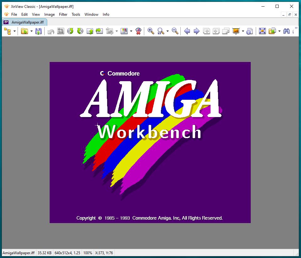
XnView Classic displaying an Amiga IFF image on a PC.


And that pretty much wraps up Part 5 of my Amiga OS 3.1.4 installation guide. Enjoy the fresh lick of paint and tune-up this gives your Amiga!

Installing Amiga OS 3.1.4 – Part 4 – Installing Workbench

Having created the physical floppy disks in Part 1, installed the 8GB CF card and ROMs in Part 2 and partitioned the CF card in Part 3 it is now time to look at installing Workbench 3.1.4.

The first thing to do is boot up the Amiga using the 3.1.4 ‘Install’ disk. Once the desktop has loaded open the Install disk and look inside the ‘Install’ directory. There will be a bunch of different language installers so run the one that you need, which for me was the English one.


Installing Workbench

Various Workbench installers in different languages…


This will load up the Installer and give you a little introduction about what it will do. Click ‘Proceed’ to begin.


Starting the installation.


Now you will be presented with another window that will allow you to add additional languages to an existing install. As this is a clean install just click on ‘Install Release 3.1.4’.


Requester giving option of installing another language.


Next you need to choose the installation mode – I chose Intermediate.


Installing Workbench

Selecting Installation Mode.


Installation Mode?

After selecting either Novice, Intermediate or Export User and then ‘Proceed with Install’ you are presented with the Installation Options screen. Here you can choose to ‘Install for Real’ or ‘Pretend to Install’. I believe this could well be unique to the Amiga? I certainly don’t recall ever having the option to do a pretend install on any other system. It can be useful to perform a pretend install on occasions as it lets you discover any potential issues and gives you a chance to fix them before committing to the actual install. However as this is a clean install we’re going to select ‘Install for Real’ and then boldly hit that ‘Proceed’ button.


Install for Real… or Pretend?


You should see a brief message about ‘Release 3.1.4’ being installed on the Workbench partition. This is because it has detected it is the first bootable partition – if you gave yours a different name back in Part 3 then it will be shown here.


Installing Workbench

This is where the actual installation starts.


Click the ‘Yes’ button to begin the installation and then choose which language(s) you want installing on the next screen. For my install I just wanted English so just left that option ticked.


Installing Workbench

Pick what languages you want installing.


Next you need to select what printer drivers you want. I selected them all because space is not an issue and you never know what you might want to hook up to your Amiga in the future.


Amiga Printer Driver Request Screen

Choosing a which printer drivers to install.


Another decision needs to be made on the next screen about which keymaps are required. Or in other words what language setting do you want for your keyboard. In my case as I live in the UK I chose a British layout before clicking ‘Proceed’.


Choosing a keyboard language or ‘keymap’.


Let the Disk swapping commence!

After a few moments you will be asked to insert the Workbench disk. There should be no need to click proceed, your Amiga should detect the presence of the swapped disk and continue automatically.


Installing Workbench

Insert Workbench Disk Screen


A bunch of files will be copied across to your new System drive.


Amiga copying files across.

Workbench install – copying files.


And then you will be asked to insert the Locale disk.


Insert Locale Disk Screen


Which will copy more files across… before asking for the next disk – Fonts.


Insert Fonts Disk Screen


Then the Storage disk…


Insert Storage Disk Screen


And then finally it will ask you to re-insert the Install disk.


Insert Install Disk Screen


Now at this point I was faced with the following warning as I had an accelerator installed with a 68030 CPU. I was able to click ‘Proceed’ and carry on but a version of this warning would pop up every single time I booted up my Amiga until I sorted it. Click here and then head down to the bottom of the page for information on how to resolve this issue.


Installing Workbench

CPU Warning.


And that should be your Worbench 3.1.4 install complete!


Installing Workbench

Congratulations – Workbench Install Complete!


Remove the floppy disk from your Amigas drive and reboot it. If all has gone to plan your Amiga should silently boot into Workbench 3.1.4 looking a lot like the photo below with all your partitions visible on the desktop.


Amiga Workbench

Amiga Workbench 3.1.4 Screen.


And that concludes Part 4 of my Amiga OS 3.1.4 installation guide – Installing Workbench.

Now we could leave it here, after all we now have a fully operational installation of Workbench 3.1.4 on our Amiga. However there are a few more things we can do to tweak and improve the install and I will cover these in Part 5.

Installing Amiga OS 3.1.4 – Part 3 – Partitioning a Compact Flash Card

Compact Flash Card

Having created the physical floppy disks in Part 1 and installed the 8GB CF card and ROMs in Part 2 it is now time to set about partitioning and formatting the compact flash card so we can install Workbench 3.1.4 on it (in Part 4).

To start the process of partitioning a compact flash card I booted my Amiga off the 3.1.4 Install disk. Once it booted I ran the HDToolBox program found inside the ‘HDTools’ directory.


HDToolBox

HDToolBox Program


This brings up the window below where you can see all of your installed hard drives. Mine is listed as a SCSI unit which is normal as this is how the Amiga sees the internal IDE controller.


Amiga HDToolBox

Amiga HDToolBox Main Window


Clicking on ‘Change Drive Type’ brings up the window below. As this is a new CF card there is nothing on it yet so you must click on ‘Define New’.


Amiga HDToolBox - Selecting a Drive

Amiga HDToolBox – Defining a New Drive


Which brings up the the ‘Define a New Drive Type’ screen. You need to click ‘Read Configuration’ at this point which will bring up another message. Simply click ‘continue’ to move on here.


HDToolBox

Informational Message


The software will then take a moment to scan the CF and identify the size and parameters needed to access it.  After the scan has completed it will display this info in the window as seen below.


HDToolBox

Drive Parameters


Now you can simply click ‘OK’ to get back to the ‘Drive Type’ window and then click ‘OK’ once more. At this point you will be warned ‘Are you sure you want to change the drive type for the current drive?’ Clicking ‘Continue’ will return you to the main HDToolBox screen once more.


Amiga HDToolBox

Back to the main screen but now with a ‘Changed’ drive status.


Now that HDToolbox knows the ins and outs of our CF card it is time to partition it into drives. Of course we could just make it one big 8Gb partition, after all Amiga OS 3.1.4 now natively supports large drives. However I always like to split mine into at least 2 partitions to keep things organised.

To start this process click on ‘Partition Drive’.


Partitioning a CF (Compact Flash) Card

Select ‘Partition Drive’.


Which should bring up the partitioning window as shown below.

I chose to make my first partition 500MB, this will be my System/Workbench drive. To select the size you simply drag the little triangle pointer and slide it along the bar. It’s virtually impossible to size a partition exactly so just get it as close as you can.

You need to give the partition a name – I called it DH0. I also ticked the box to make it bootable as this is the first partition and will be the one the Amiga will boot off.


Partitioning a CF (Compact Flash) Card

Creating the first partition.


To create another partition you click ‘New Partition’. Don’t be tempted to click the ‘OK’ button until you have finished creating all your partitions. For my second partition I called it DH1 and made the size approximately 1.5GB. I will be using this to install applications and save documents to. I will probably keep a small selection of music on this drive too.


Partitioning a CF (Compact Flash) Card

Creating the second partition.


I left my biggest partition for last so it could use all of the remaining space on the card. This worked out at a little less than 6GB in total. I called this partition DH2 and this will be where I install WHDLoad games.


Partitioning a CF (Compact Flash) Card

Creating the third partition.


You can click each of your partitions in the bar to check their details. Once you are happy that they are all exactly the way you want them to be, hit ‘OK’. You should then be back to the main HDToolbox window.


Partitioning a CF (Compact Flash) Card

HDToolBox with ‘changed’ drive status.


You must now click ‘Save Changes to Drive’ for all the settings you have configured up to this point to be written to the disk (CF card). The window should then change to look like this:


Amiga HDToolBox

HDToolBox back to ‘Not changed’ status.


Congratulations! Your new Amiga drive has now been prepped and partitioned! The final step is to format the partitions. To do this you need to reboot the Amiga whilst leaving the Install disk in the drive so it can boot off it.


Uninitialized Amiga Disks

The three partitioned but currently ‘uninitialized’ drives created earlier.


When your Amiga has finished rebooting you should see a screen similar to the one above. You will notice that the partitions show either as ‘Uninitialized’ or just as a weird name (or both in my case).


Amiga Icons Menu

The Format Disk menu item.


They now need to be formatted so that the Amiga can actually use them. To format a partition you just click on its icon and then select ‘Format Disk’ from the ‘Icons’ menu.


Formatting a Partition

Formatting and Naming DH0.


In the above example I called my DH0 partition ‘Workbench’ but you can call yours whatever you like. If you are interested in the new long file names feature of 3.1.4 now would be a good time to select that tick box.


Disk Format Warning

First format warning…


Make sure you select ‘Quick Format’ or you’ll be waiting a very, very long time for the format to finish. You will get a couple of scary warnings that give you an opportunity to back out if you’ve accidentally selected the wrong disk to format.


Disk Format Warning

Second and final format warning.


Click ‘Format’ in response to both of the warning messages to seal the deal. A few seconds later a drive on your newly partitioned and formatted compact flash card should appear on the workbench screen. Now simply repeat this process for each partition you created earlier.

And that concludes Part 3 of my Amiga OS 3.1.4 installation guide – Partitioning a Compact Flash Card.

I must admit I had originally intended to include the Workbench install in this part too but decided against it as I thought this post was long enough already. Therefore I will be covering the installation of Workbench in Part 4 shortly.

TerribleFire 330 – CD32 Upgrade

TerribleFire 330

One of the things I’ve always loved about the Amiga is it’s expansion possibilities. There was always some upgrade or gizmo you could add that would let you do something new, or do something faster. The TerribleFire 330 is touted as being able to do both of these things and then some. Naturally, as soon as I spotted it on AmiBay I wanted one…

What is it?

The TerribleFire 330 is an expansion for the Amiga CD32 that adds many new features to the console. It’s attached by means of a ‘Riser’ card to the expansion port which itself offers some benefits to the user. Here’s a quick run-down of the extra features it offers:

  • 68030 CPU over-clocked to 50Mhz
  • 64MB Fast Ram
  • IDE Interface
  • RGB Video Port (on the riser)
  • PS/2 Keyboard port (on the riser)

In a nutshell, it converts your CD32 into a souped up Amiga 1200 with built-in CD-ROM drive.


A Closer Look at the TF330


TerribleFire 330

Here’s a close-up of the top of the board. CPU on the left, IDE connector top right.


TerribleFire 330

Here’s a view of the underside of the board. Foam pads are present to prevent the exposed solder pads from touching the metal shielding cover inside the CD32 when inserted.


TerribleFire 330 Riser Board

Here’s a view of the riser board.


Riser Board

The is a straight-on view of the riser board. The male DB25 port on the right is for hooking up an RGB video cable for vastly improved picture quality. The PIC chip in the center provides a means of converting the inputs from a PS/2 PC keyboard into key presses that will the Amiga will recognise.


TF330 PS/2 Port

A better view of the PS/2 port.


TF330 68030 CPU

Close-up of the 68030 CPU. As you may notice it’s officially rated at 40Mhz. On the TF330 board it has been overclocked to run at 50Mhz.


TerribleFire 330

Side view of the TF330 – note how the CF card can be tucked underneath.


TerribleFire 330

Another view of the TerribleFire 330 card.


Installing the TerribleFire 330


Installation is pretty straightforward and involves removing the plastic expansion cover on the back of the CD32 console. There’s only one phillips screw to remove. Both the screw and the cover can be safely stashed away at this point as they won’t be getting used again.


CD32 Expansion Cover

This is the CD32 expansion bay where the TerribleFire card will be installed.


With the cover removed you can clearly see a big empty space left above the shielding. This expansion bay was original intended to allow the use of the official Commodore CD32 Full Motion Video Module.


CD32 Expansion Bay

Here’s a view of the expansion bay with the cover removed. The edge connector can be seen at the bottom of the image. The TerribleFire 330 card will occupy that empty space above the shielding.


You can simply install the TF330 as it comes but I found a nice little 3D printed clip to hold the IDE cable and CF card in place on eBay. With this fitted the card is securely held underneath the main TF330 board out of harms way. Not an essential purchase but as I store my CD32 vertically I thought it was a worthwhile extra to prevent things moving around.


This slideshow requires JavaScript.


Installing the TerribleFire 330

Here are some photos of the TF330 after I installed it. It does protrude from the back of the console somewhat and it certainly ain’t ‘pretty’ but I’m more than happy to overlook this given the features it offers.


Installed TerribleFire 330

TF330 fully installed – you can clearly see that it protrudes about 1″ from the back of the console to the edge of the PS/2 port.


TF330 Riser installed

The transparent plastic stuck over the circuit board protects it from being shorted out accidentally. The PIC chip is missing for reasons that I will explain later…


Booting up for the first time

My TerribleFire 330 came with a pre-installed copy of Workbench on an 8GB Compact Flash card. To boot into Workbench all you need to do is turn on the CD32 without a disc inside it. After a few seconds the CD activity light starts to flicker away and then up pops the workbench screen.


TF330 Workbench Screen

You can see the 68030 CPU recognised along with the extra 64MB of RAM on the title bar of the screen.


As with any accelerator upgrade for the Amiga I couldn’t resist loading up Sysinfo to see how my pimped out CD32 fared against other systems in the Amiga range. I was not disappointed, it ranked between the Amiga 3000 and 4000 which is impressive. It’s almost twice as fast as a stock A3000 which has a 25Mhz 030 processor.


TerribleFire 330 Sysinfo

SYSINFO: Nearly half as fast as an Amiga 4000…


TerribleFire 330 Sysinfo

SYSINFO: Zoomed in view.


And of course with the ability to run Workbench off an installed CF card comes the option of using WHDLoad! My card came pre-installed with hundreds, if not thousands of games all ready to play with a few clicks of a mouse. The CD32 already has the required 2Mb chip RAM and with the TF330 it also has plenty of Fast RAM now too. Throw in a PS/2 keyboard and you can also exit games cleanly back to Workbench and play games like Star Crusader that require one.


CD32 WHDLoad

TerribleFire 330 lets you use WHDLoad on the CD32.

Compatibility

I’ve now tested all the games I own and listed the results on my CD32 Game Compatibility page.

The board was described as having a ‘disable jumper’. Removing it is supposed to make it invisible to the CD32 so it can boot up as normal. However in my testing this simply doesn’t work, in fact removing the jumper prevented my console from booting up at all. I contacted the seller on AmiBay who said there’s still a bug with this and that it would hopefully be fixed in a future firmware update. If that ever happens I’ll update this article.

As things stand right now I can either remove the board if I come across an incompatible CD32 game or see if there’s an alternative version on the internet that has been patched to work. Alternatively I can also try the WHDLoad version.


RGB Video Functionality


The RGB port works exactly as described and offers a beautifully crisp, vibrant display with a regular Amiga RGB SCART cable. Much better than the composite I was having to use previously. Whether or not I was using Workbench or playing a game off CD this worked flawlessly.


TerribleFire330 RGB

A beautifully crisp display thanks to the TerribleFire 330’s RGB video output.


PS/2 Keyboard Functionality


Unfortunately I can’t say the same for the PS/2 port. The whole point of this is to allow people to use cheap PC PS/2 keyboards with the CD32 instead of super scarce Amiga ones. However I tried three different brands of PS/2 keyboard and only one of those worked… for about 10 minutes. No matter what I tried I couldn’t get that keyboard to work reliably. It turns out that the PS/2 keyboard compatibility is very poor with the riser card. People report greater success with really old keyboards rather than currently available ones. I was advised by the seller to get a CD32 AUX to PS/2 adapter.


This slideshow requires JavaScript.


I chose one of these on eBay for about £18. The seller was really helpful and even offered to refund me if the adapter turned out not to work. Thankfully that wasn’t necessary as it worked perfectly with my cheap Genius PS/2 keyboard that I picked up off Amazon. There’s some clever electronics hidden inside the adapter that converts stuff like the two ‘Windows’ keys into ‘Amiga’ ones so you can still do a soft-reset. It works really well and I highly recommend getting one, even if you don’t get a TerribleFire!


This slideshow requires JavaScript.


Actually there was one other issue that I had to solve before I was in PS/2 keyboard nirvana. The keyboard initially behaved like a key was stuck down. There is a conflict between the PIC chip on the Kipper 2K riser and the PS/2 Aux adapter. Simply removing the PIC chip solved this problem completely with no negative effects.

Here’s the PS/2 keyboard I’m using with my CD32, it’s just a cheap one I picked up off Amazon but it does the job and isn’t a bad match for the dark grey colour of the console either.


CD32 PS/2 Compatible Keyboard

CD32 PS/2 Compatible Keyboard


Conclusion

I can’t deny it’s shame the built-in PS/2 keyboard option doesn’t work as well as it could and that I can’t disable the board without removing it. However these small niggles don’t stop the TerribleFire 330 from being a beast of an expansion for the money. You’d be hard pressed to find anything else offering as much bang for your buck.

With the TerribleFire 330 installed my CD32 has become the ultimate Amiga gaming machine. It can play CD32 and CDTV titles and thanks to WHDLoad it can now play pretty much any other Amiga title as well. In fact with mouse and keyboard attached it can even be used for productivity stuff just like an A1200, only with a built in CD-ROM drive!

The extra grunt of the 50Mhz 030 also helps it run games like Alien Breed 3D, Frontier Elite 2 and Wing Commander at their very best. The addition of the RGB video port makes everything look its very best too! Bottom line, if you have a CD32 then the TerribleFire 330 is an essential upgrade for it.


Ultimate Amiga gaming machine

With the TF330 my CD32 has become the ultimate Amiga gaming machine.

Modding Amiga 500 Floppy LED to Display IDE Activity

Introduction

Unlike the Amiga 1200, the A500 was never designed to allow the fitment of an IDE Hard Disk Drive (HDD) inside it so naturally it never included an HDD activity LED. For the longest time this was never really an issue. Sidecar expansions such as the A590 were the only way to add HDD’s to the A500 and they came with their own drive activity LED. However, now that many owners are fitting expansions like the Vampire into their Amiga 500, things are a little different. These new devices facilitate the use of 2.5″ HDD’s or Compact Flash (CF) cards inside the casing of the A500, something that was never possible before.

The problem with this is the lack of a drive activity light. It can be quite disconcerting at times when you turn on your ‘Vampired’ Amiga 500 and nothing appears to happen. You sometimes wonder if it’s actually booting up or simply frozen. The same issue crops up whilst loading a game or running a program. There’s simply no way to tell if your Amiga is doing anything, especially if you’re using a CF card as they are completely silent. At least if you have a 2.5″ HDD they do at least make some sounds whilst being accessed.

Wouldn’t it be great if you could add a hardware activity light to your A500 to solve this issue? Well, recently I stumbled across a nifty little mod from Arananet that claimed to allow you to do just that by using the Amiga 500 floppy disk activity LED to show IDE HDD/CF activity. It’s called the ‘IDELED’ and is only €7 plus postage so I ordered one and sat back waiting for it to arrive. (Direct link to the Amiga 500 IDE activity LED can be found here).

Incidentally, if you fancy making this modification yourself all you need is a phillips screwdriver (to open the A500 case up), some wire cutters/strippers and a soldering iron. Don’t worry if you’re not an expert solderer, I’m rubbish at soldering but this is very basic stuff and should be well within most peoples capabilities.

A closer look at the IDELED device

The device arrived in a little anti-static bag with no instructions. It’s a tiny little 1″ square circuit board that incorporates an 8 pin socket one one side and 8 pins on the other. There is also a small hole for you to solder a wire to, plus a few components that allow it to ‘do its thing’.

This slideshow requires JavaScript.

Getting Started

The IDELED is designed to sit between the Amiga 500’s keyboard connector and the keyboard cable. This gives it access to the floppy drive LED circuit and allows that to be used as an IDE activity LED in your Amiga 500. After opening up your A500 the first thing you need to do is carefully unplug the keyboard connector, lift away the keyboard and set it to one side.


Amiga 500 keyboard connector

Unplug the keyboard connector (circled in red).


You’ll then have access to the 8 pin keyboard connector on the mainboard which will look like this:


Amiga 500 keyboard connector pins

Keyboard connector pins


Next you need to attach the IDELED board to the keyboard connector pins on the mainboard. Make sure that you connect it the correct way around – orient the board so that the keyboard connector is at the back if you are looking at it from the front of your Amiga. It should then look like this:


IDELED board

IDELED fitted to keyboard connector


At this point I connected the keyboard to the pins on top of the IDELED board. You might want to leave doing this until after you’ve soldered the connecting wire but I needed to experiment a bit and wanted the A500 powered on and the LED’s working. At this stage the project looked like this:


Amiga IDELED board

IDELED board fitted between mainboard and keyboard cable


Solder time

The next job is to attach a short wire to that little solder point on the left side of the IDELED board. The wire needs to be long enough to reach the IDE connector on top of your Vampire (or other accelerator card) with enough slack so that it’s never under any strain if you have to move things around in the future. You will need to strip off a few millimeters of insulation from each end of the wire before you go any further. It’s much easier to do this before one end of the wire is attached to anything. I’d also suggest ‘tinning’ the exposed wire each end as this makes soldering them easier.

Insert one stripped and tinned end of the wire into the little hole in the board and apply a blob of solder. You should now have something looking like this:


Amiga 500 IDELED board

IDELED board with ‘activity’ wire soldered on


Locating pin 1 and 39

The other end of the wire needs to go to ‘pin 39’ on your IDE adapter. This is the pin responsible for transmitting drive activity. If you have a CF adapter like mine (pictured below) then you should be OK to just hook the wire up to the same pin as I did.


Amiga Compact Flash IDE adapter

A closer look at my IDE CF adapter (without CF card fitted)


Amiga Vampire CF flash adapter pins

Locations of pins 1 and 39 on my 44 pin IDE adapter


To locate ‘pin 39’ on my adapter I used the 44 PIN IDE connector diagram below for reference. Note the way the pins are numbered – it alternates up and down with 1 top left, 2 bottom left, 3 back to top row and so on. My particular adaptor has the upper row of 22 PINs connected to the top of the circuit board and the lower row of 22 pins to the underside.


Diagram showing pin numbering of a 44 pin IDE connector

2.5″ 44 PIN IDE pin layout & numbering


Provided it was connected up the correct way round originally, the purple edge of the ribbon cable indicates which side ‘pin 1’ should be. Thankfully the Vampire card clearly indicates where ‘pin 1’ is (see the little ‘1’ above the bats head in the photo above) so my cable was oriented correctly. Once I was sure of the location of ‘pin 1’ it was a simple matter of counting along to identify ‘pin 39’. Obviously if you have a different kind of adapter then you will have to confirm its location yourself. Hopefully the information above will help you out.


Amiga 500 IDE activity LED - pin 39 activity wire soldered on

Wire soldered to pin 39 – not the prettiest soldering job in the world but it does the job.


The completed modification


Amiga 500 IDE activity LED fitted

View showing the completed modification in its’ entirety.


Assuming you’ve connected everything up correctly (check  before you screw the case back together), you should now how a fully working IDE activity LED on your A500.


Demonstration

In the video below you can see my Amiga 500’s new IDE activity LED flashing away whilst it boots into Workbench. The loud clicking sound is just my empty floppy drives clicking – the anti-click software doesn’t run until workbench has finished loading.

I’m really pleased with this mod, it was cheap, pretty simple to implement and above all else, really useful. No longer will I be in the dark about when my CF card is being accessed!


But wait, there’s more!

When you pop in a floppy disk the activity LED still flashes away as usual so there is no loss of functionality. Quite the opposite in fact as the LED even flashes when I use an SD card (the Vampire supports SD card storage too) which is totally awesome and something I definitely wasn’t expecting. An added bonus is that because Commodore simply labelled the A500’s floppy activity light as ‘Drive’ it’s still labelled correctly! How’s that for future-proofing!?

Anyway that about wraps this article up for now. I do hope you found this article both interesting and useful. If you did, please let me know by leaving a comment below, I’d love to hear from you.