The A500 machines shipped with a graphics chip called ‘Denise’ that is responsible for handling sprites and also all the different screen modes and resolutions you can use with Workbench and other apps. The later Amiga 500+ model sported an updated chip called ‘Super Denise’ which offered quite a few more screen modes and resolution options. The Amiga 500 Super Denise upgrade is a very straightforward modification which simply involves getting hold of the newer chip and replacing the old one with it. (It is an exact pin-for-pin replacement). For more detailed info on the Denise chip look here.
Getting hold of a new chip
The ‘Super Denise’ has the chip number 8373-R4 whereas the old regular ‘Denise’ is 8362. You can usually pick up Super Denise chips on eBay – here. I paid around £20 for mine which I though was fair… be patient and wait for one at a fair price – don’t get ripped off.
Removal & Replacement of the chips
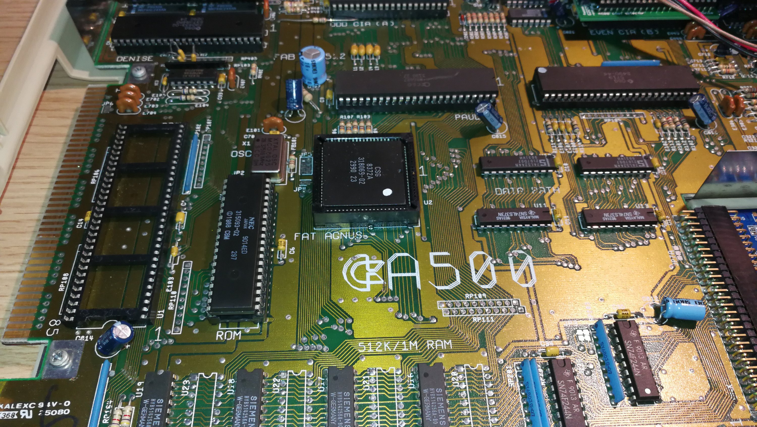
You can remove the the old chip with just a small flat bladed screwdriver if you are careful. Just lever up each end slowly, alternating from one end to the other, making sure it lifts evenly from each corner so that the pins don’t bend. Ideally though, use an ‘IC Extractor’ – it makes the job a lot easier and is a useful tool to have in your retro computer toolkit anyway. Again these are readily and cheaply available on eBay – here. The new chip should just plug straight into the socket. Make sure the marked end of the chip matches up with the notched end of the IC socket. If it goes in the wrong way around it won’t work and may even damage the chip and/or the motherboard. If the pins don’t quite line up you can bend them gently into place using a pair of pliers.
Amiga 500 Super Denise Upgrade – In Pictures
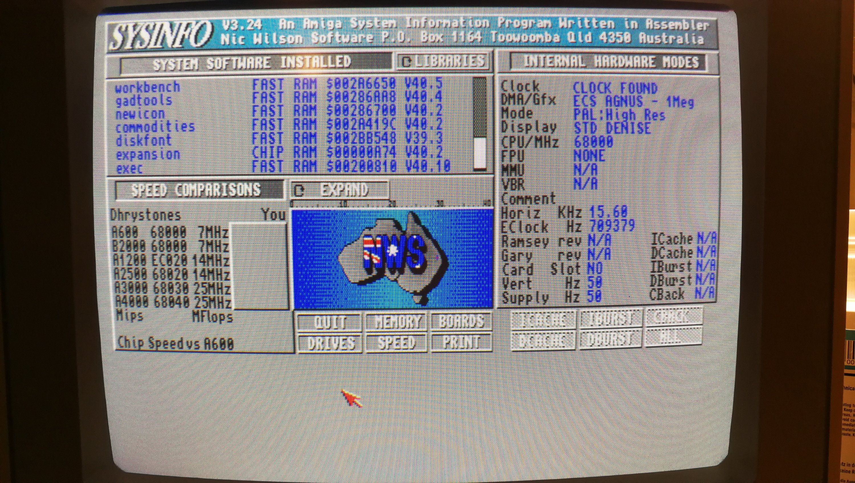
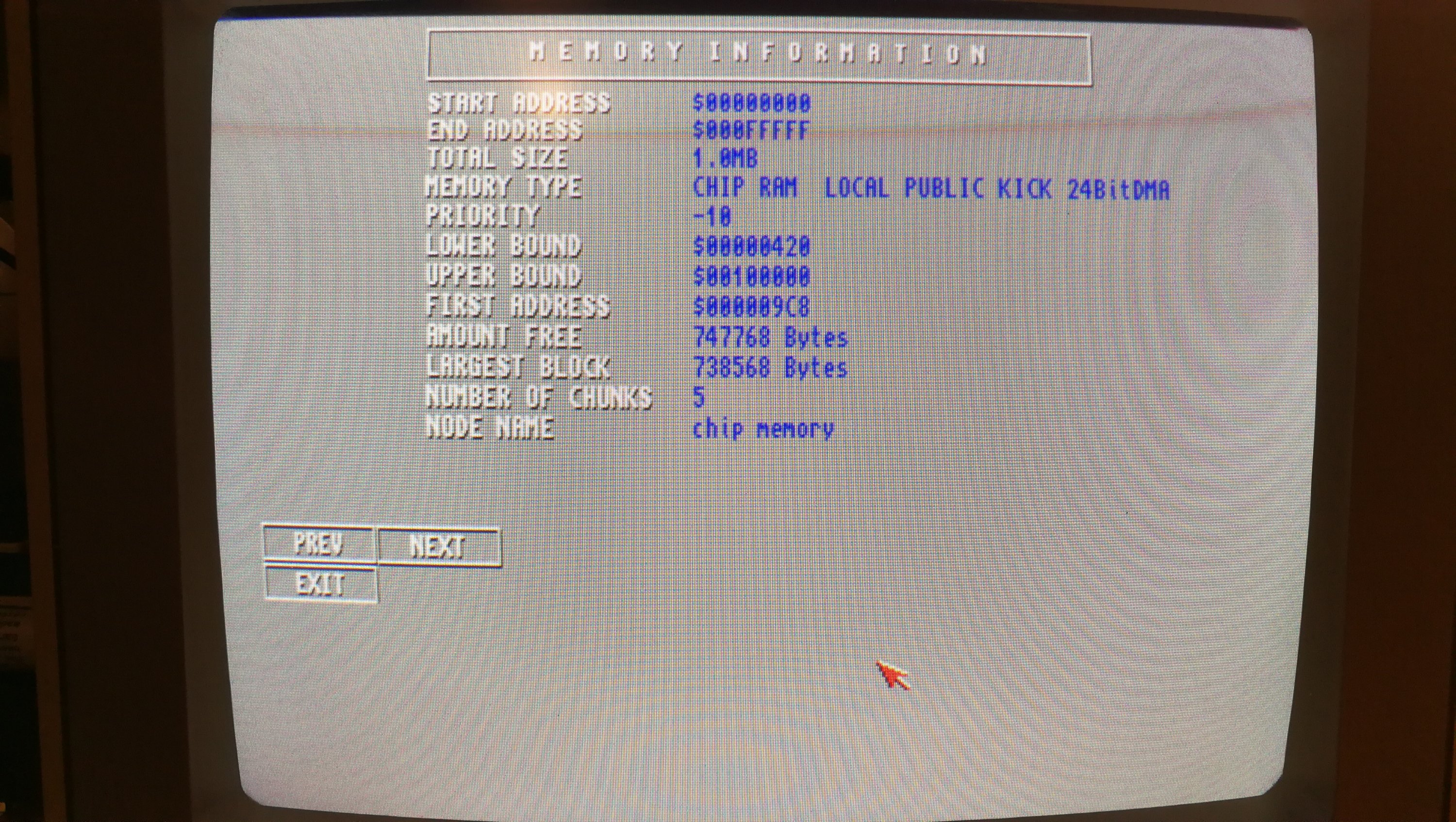
Below you can see before and after screens showing SysInfo details, and available screenmodes along with the two different Denise chips fitted. The end result is a success with more screenmodes (eg Super-Hi Res modes) available straight away, even with my standard 1084S monitor. However in order to benefit from the rest of the modes the Super Denise chip offers (such as Productivity) I need to get hold of a proper Multi-Sync monitor that can handle the different refresh rates they need.

Sysinfo Screen with Standard Denise Fitted
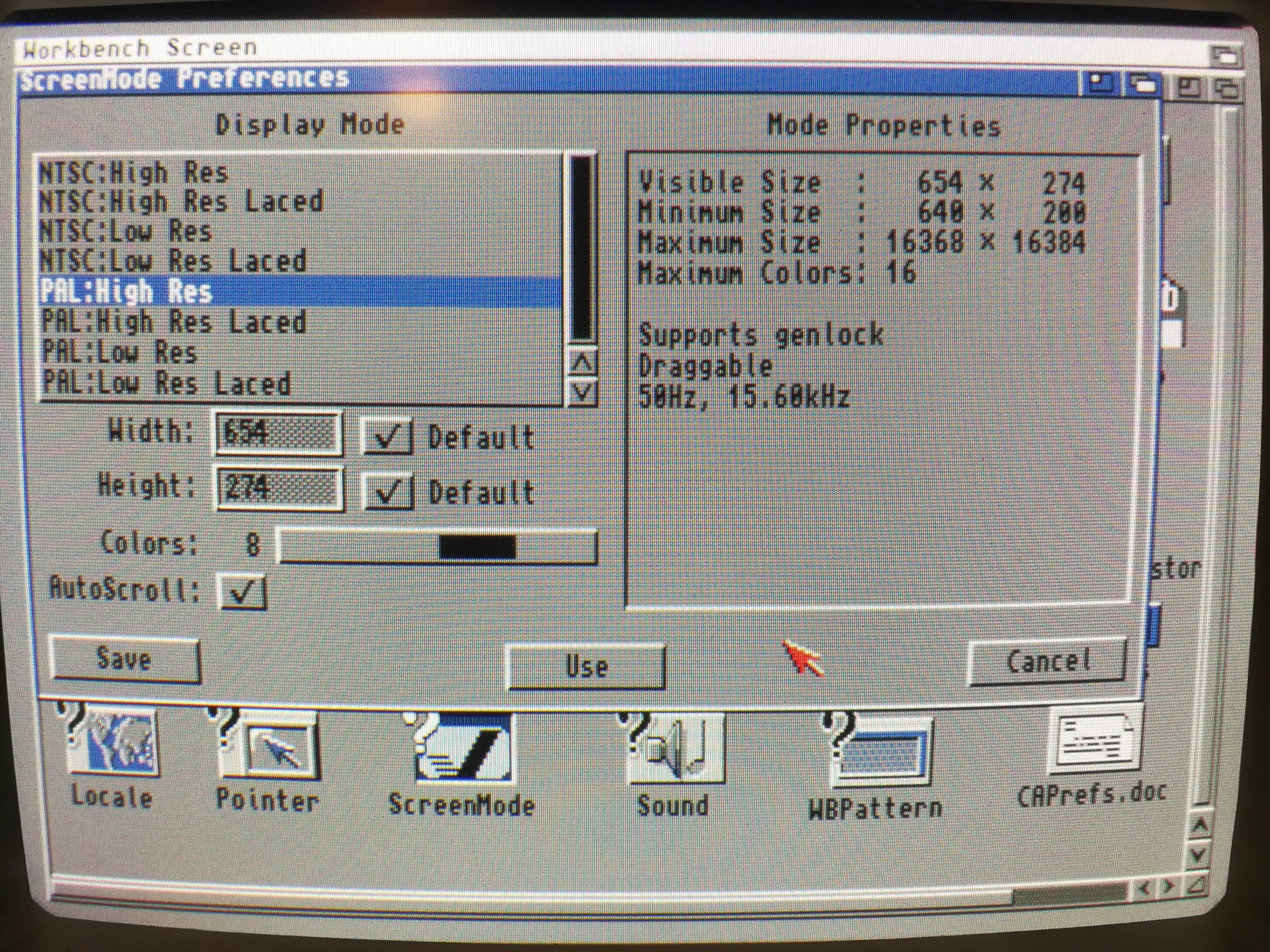
Screen Modes Available with Standard Denise Chip
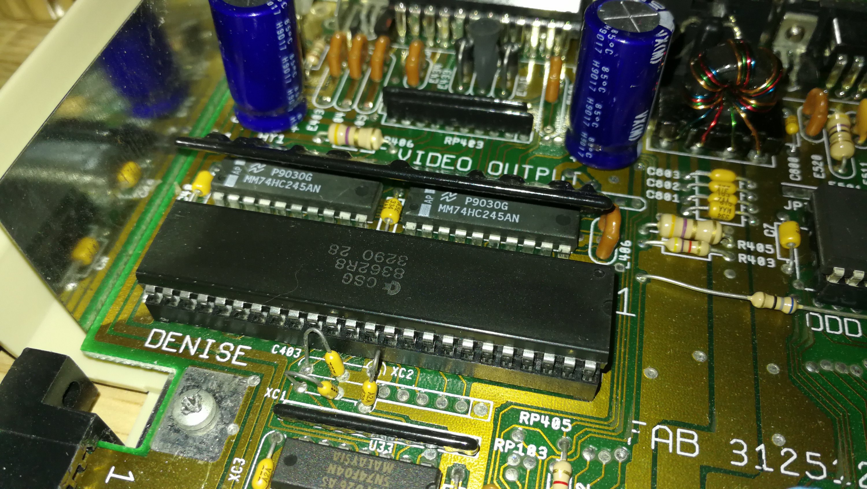
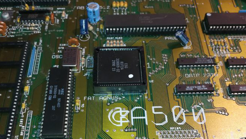
Standard 8362R8 Denise Chip Fitted
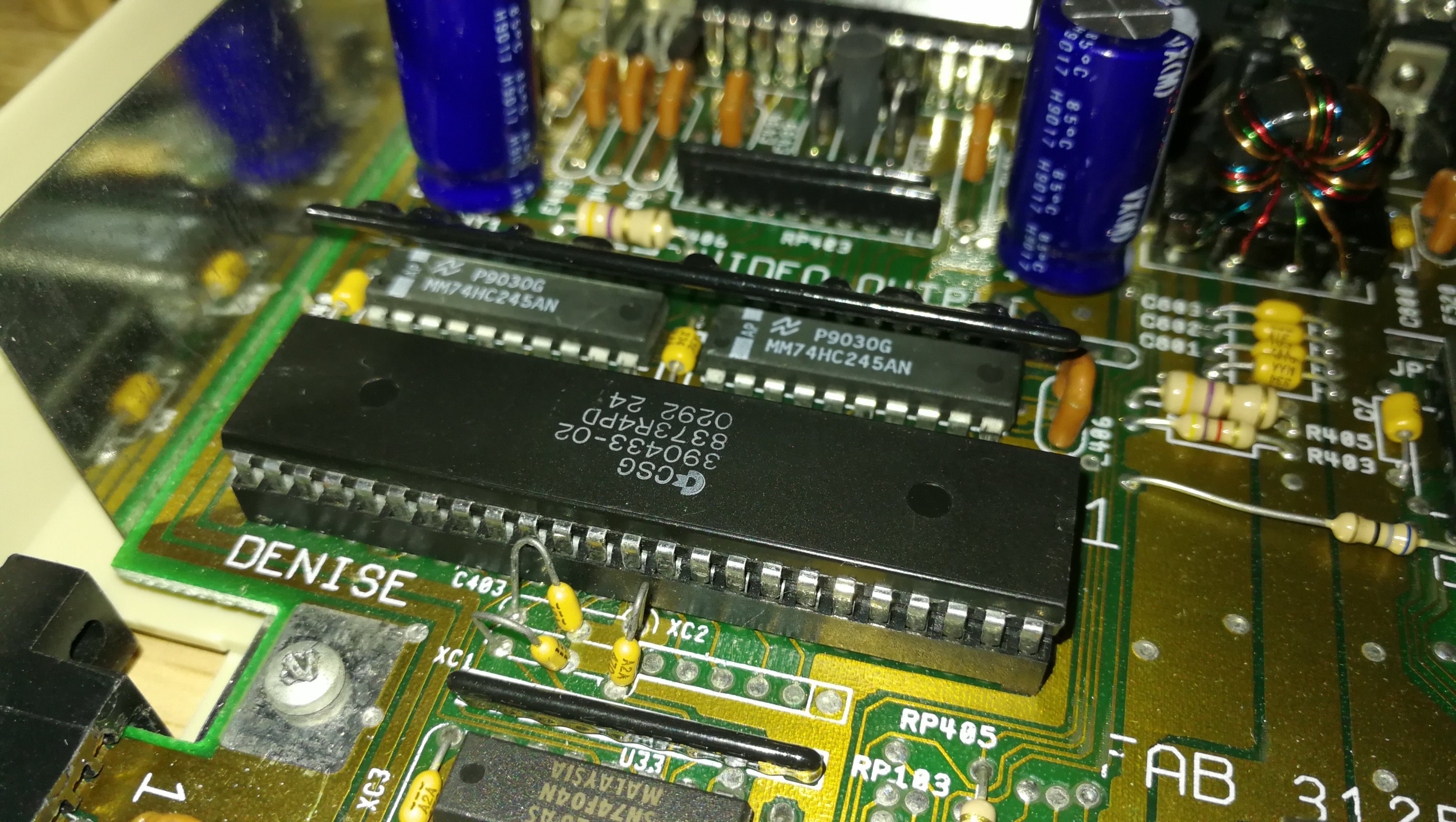
Replacement 8373R4 Super Denise Chip Fitted
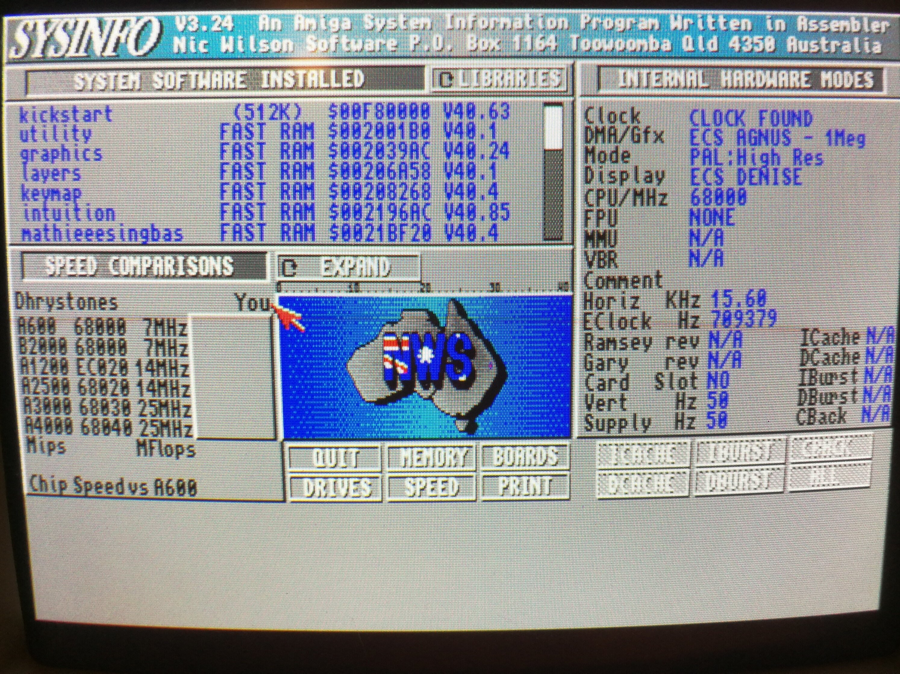
Sysinfo Screen with Super Denise Fitted
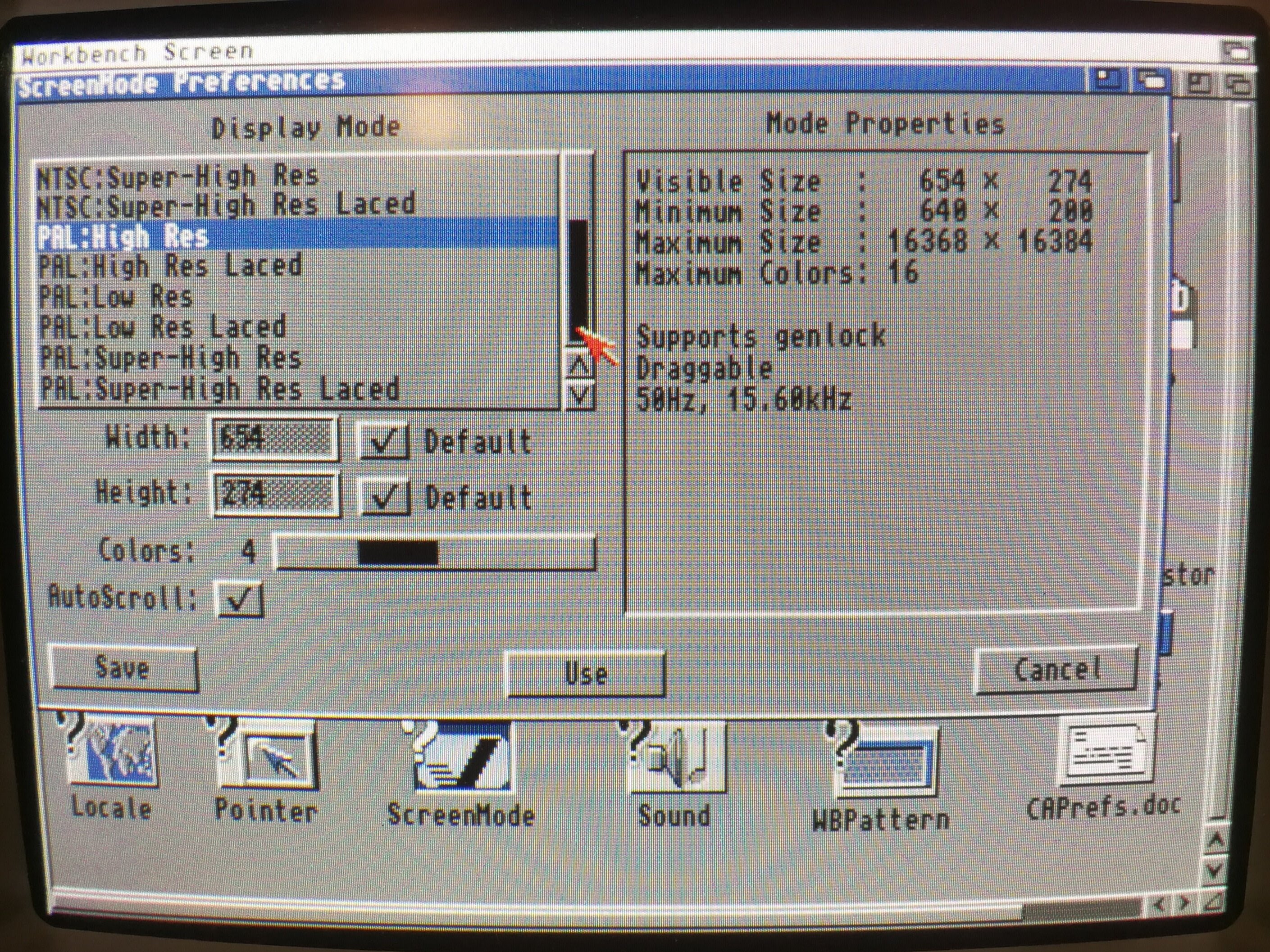
Screen Modes available after fitting Super Denise Chip