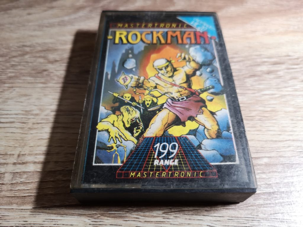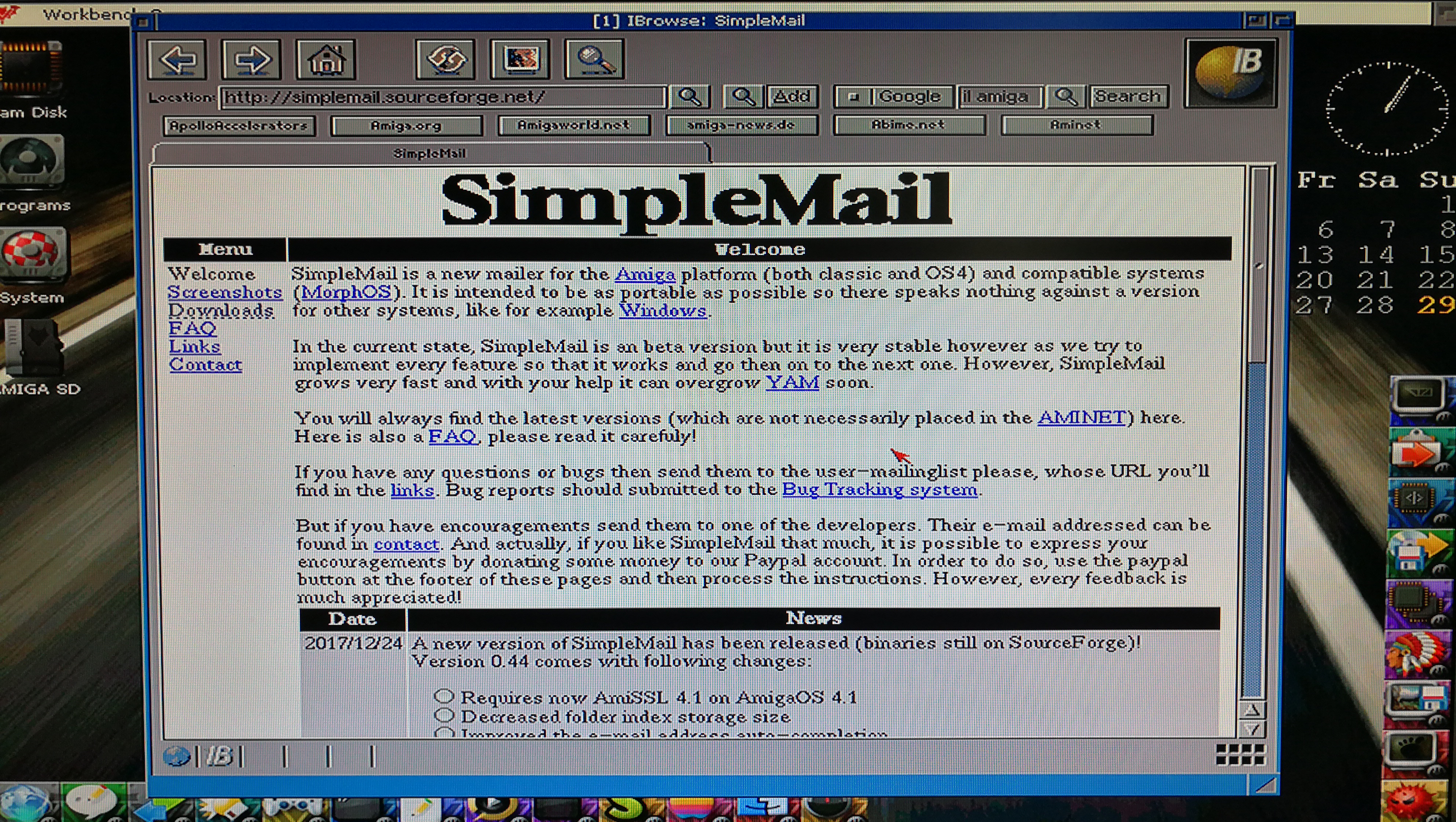
I’ve always wanted a cassette tape winder so when I stumbled across this plan on Thingiverse I thought it would make a great little project for my 3D printer. Sure I could search on eBay and maybe pick up an old one but where’s the fun in that? So here’s a little guide to how I built my own cassette tape winder.
Computer Stuff
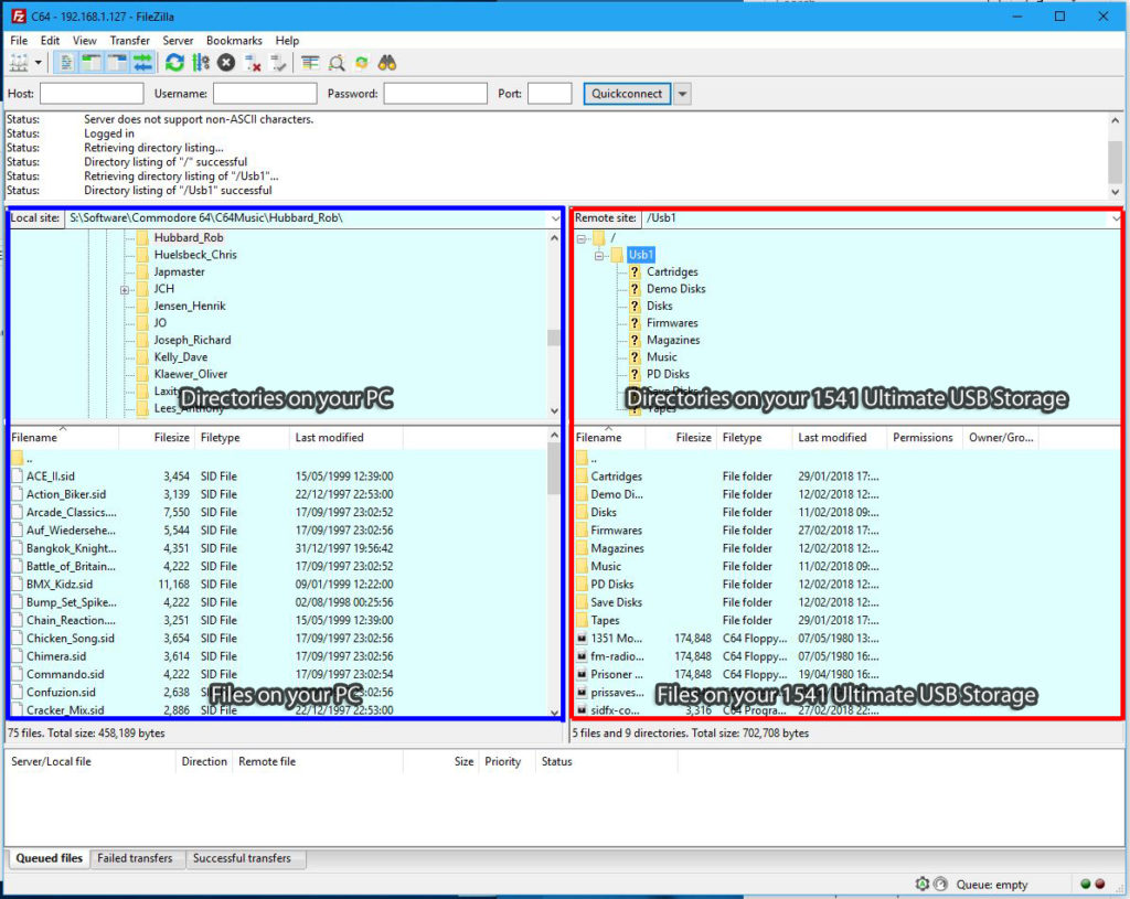
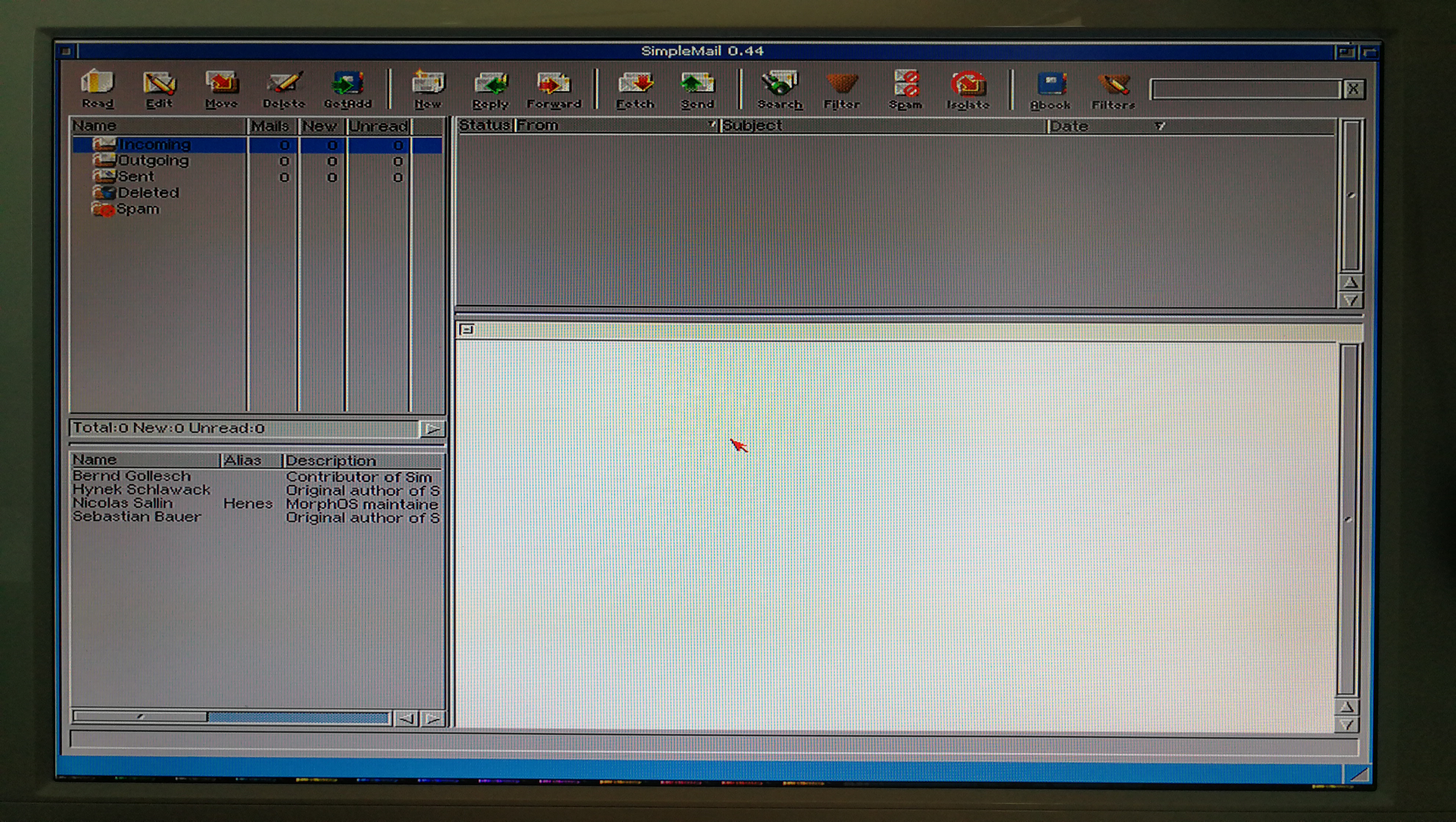
First off I had to download the zipped STL files from the Thingiverse site. (STL files contain 3D CAD objects that you can print).
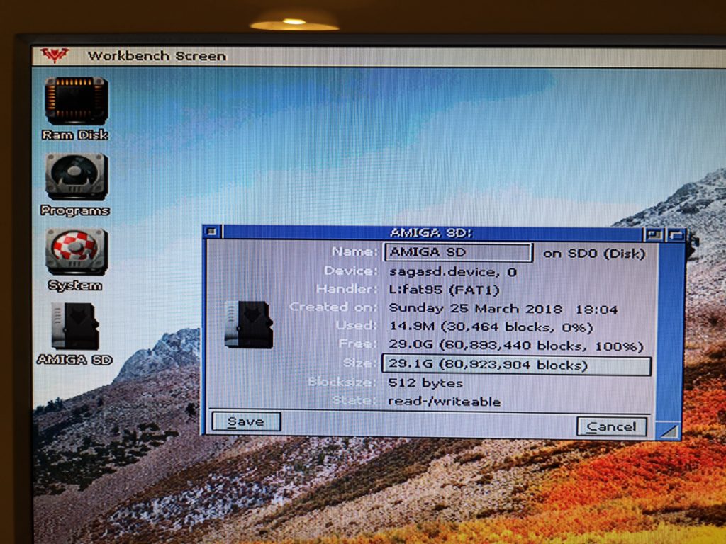
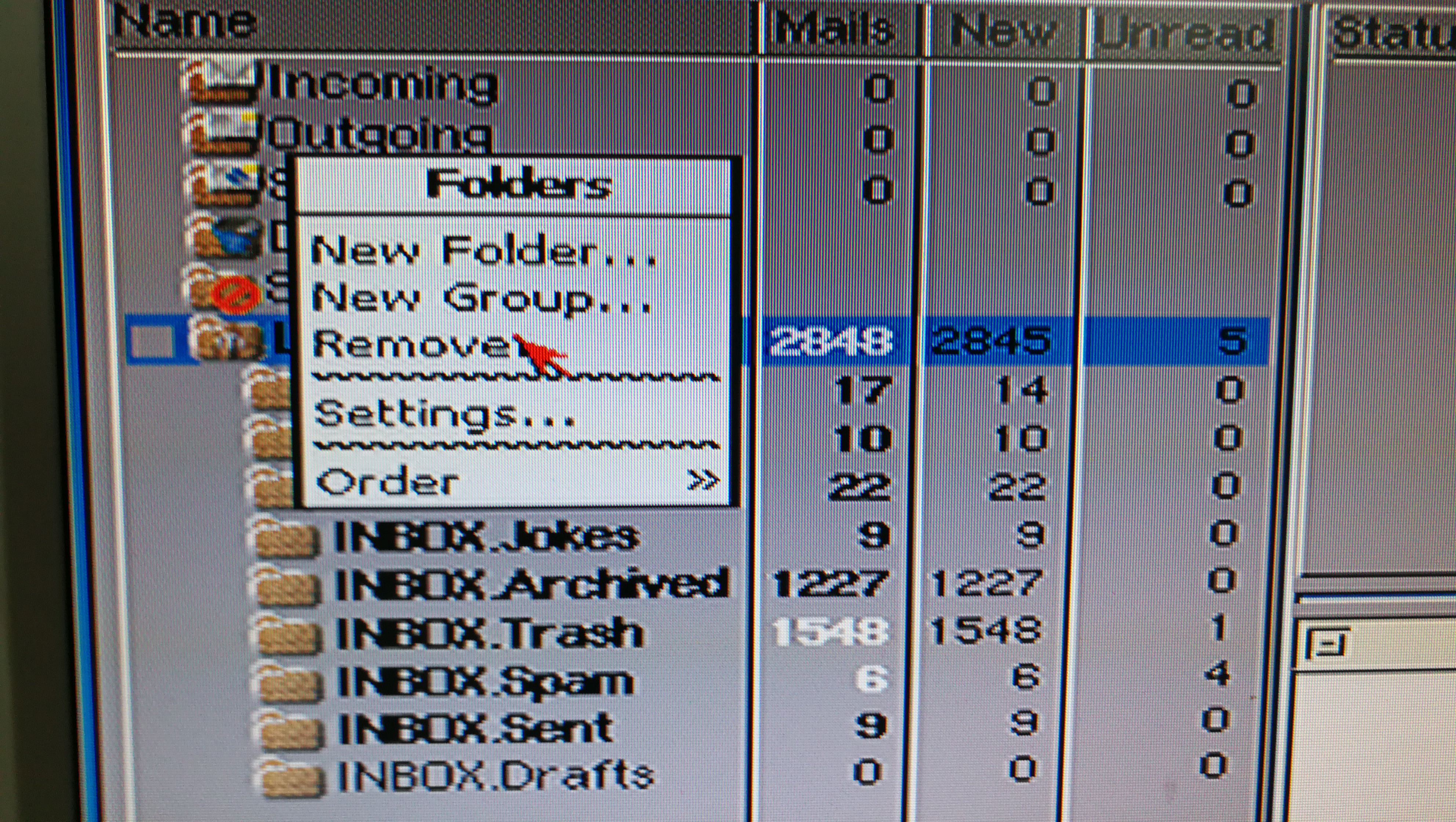
Each component has it’s own STL file and there were 10 of them for this project. You can see them all listed in the folder screenshot below.
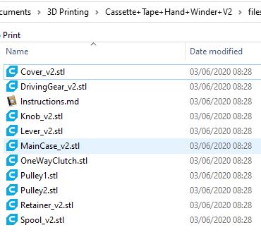
These are the components that you need to 3D print.
You cannot print STL files directly so I use a piece of free software called Cura to work with them. This software allows you to see the STL files as an interactive 3D model. It also processes STL files by ‘slicing’ them into layers that can then be saved as GCODE files and printed on a 3D printer. If you’ve never 3D printed something this might all sound very complicated but it really isn’t.
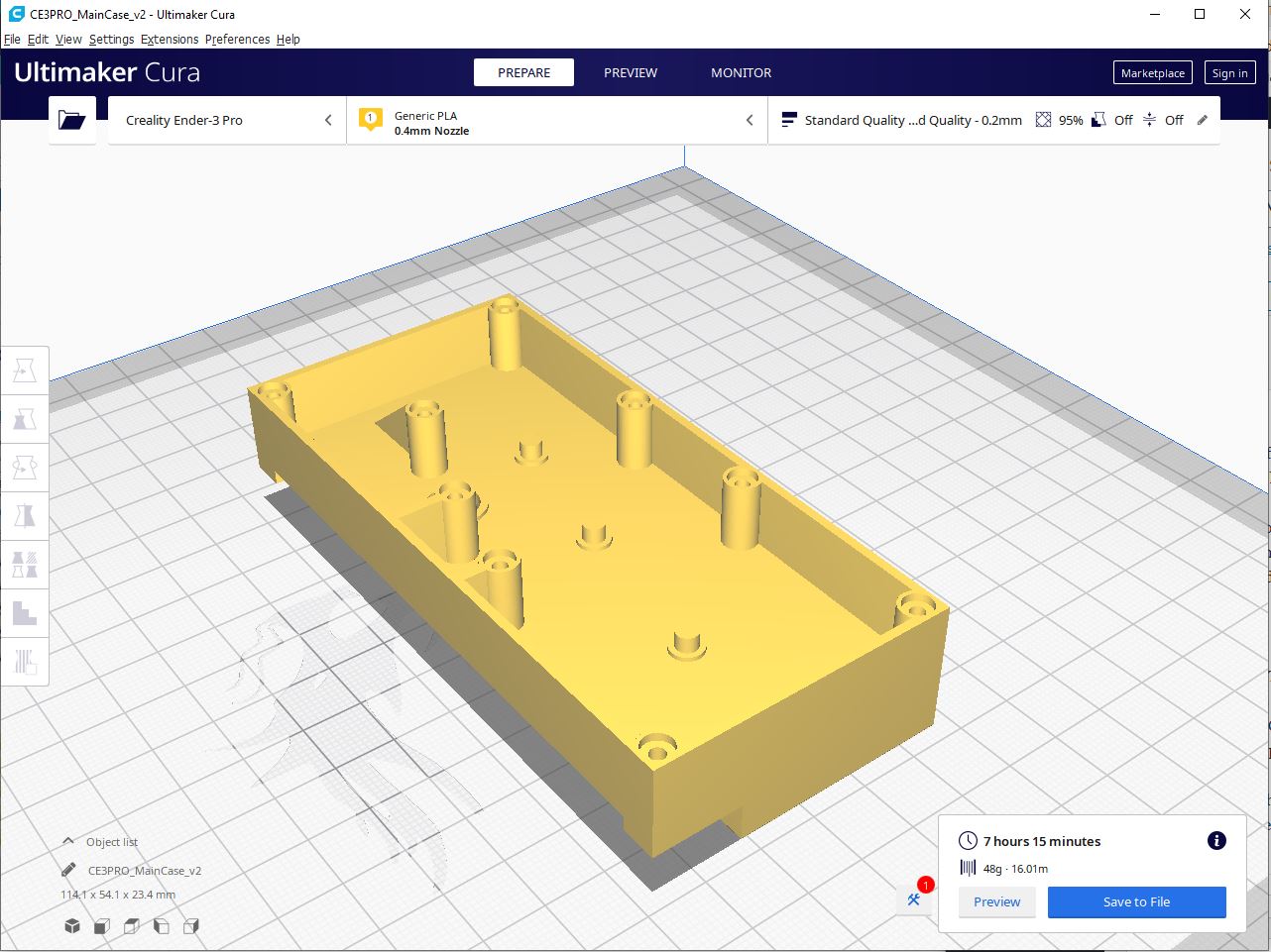
Winder case as viewed within Cura software.
The image above shows the main case for the winder in Cura. I have already sliced it and it shows an estimate of how long it will take to print, over 7 hours in this case. 3D printing is not a fast process!
Beginning the 3D Printing
Freshly printed winder case.
Above you can see the finished case print… but there’s some extra support material that will need to be removed from underneath it. 3D printers can’t print (over long distances at any rate) in thin air so they need to create a kind of scaffolding system (supports) in order to do so.
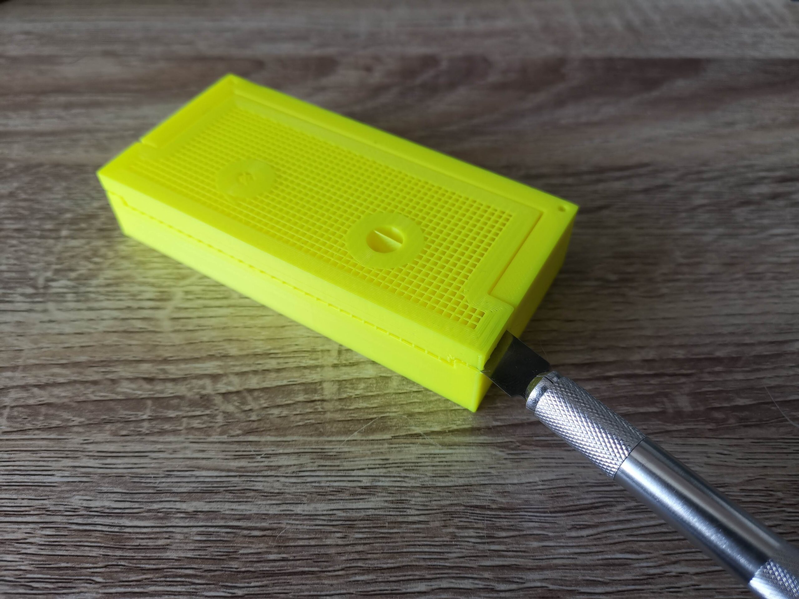
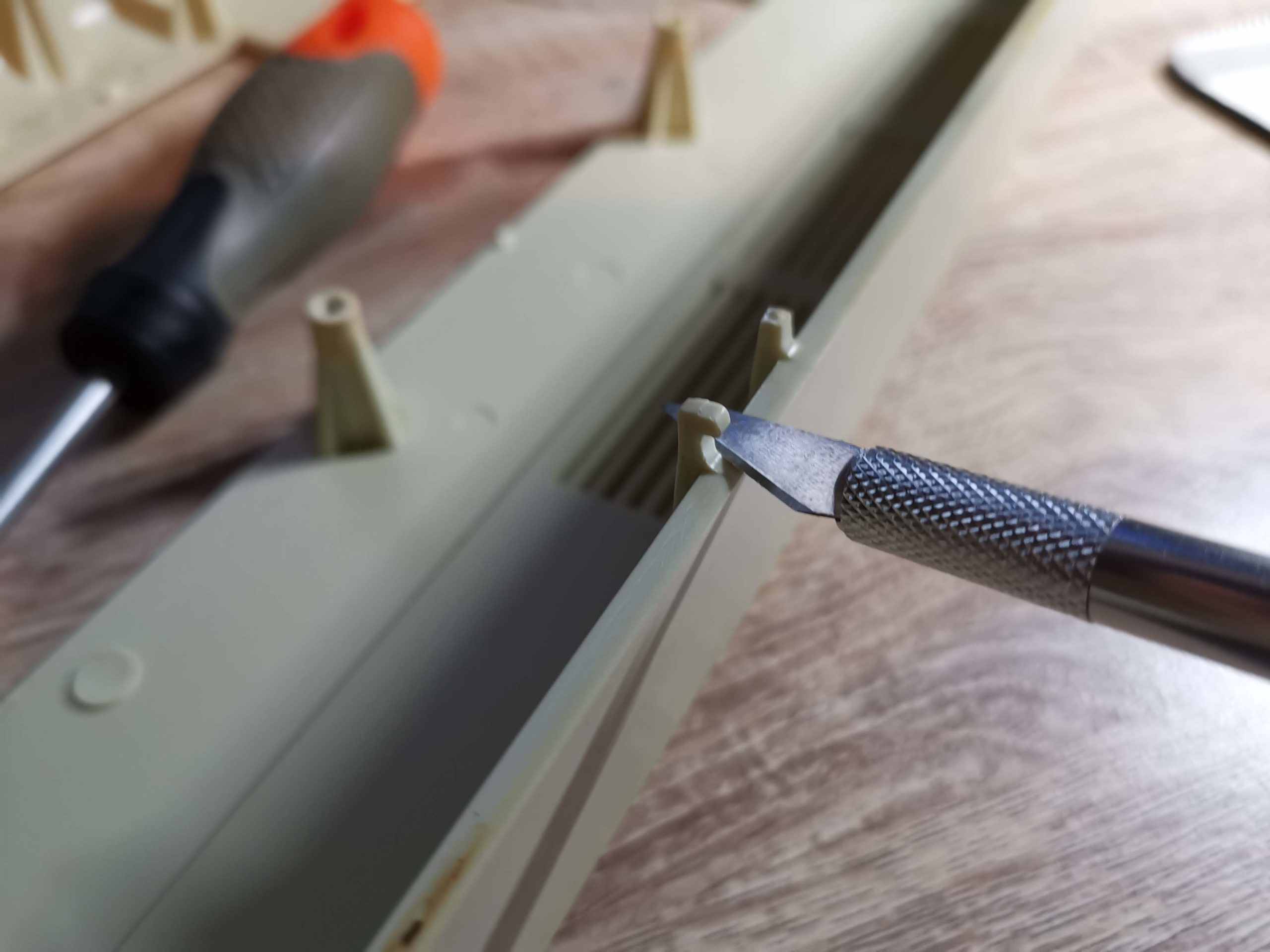
Removing the 3D printed support material.
Support material is designed to break away easily from the main print. In the above photo I used a sharp craft knife to break away the support material. It only took a couple of slices and then I was able to get my fingernail under it and simply pull it away in one piece.
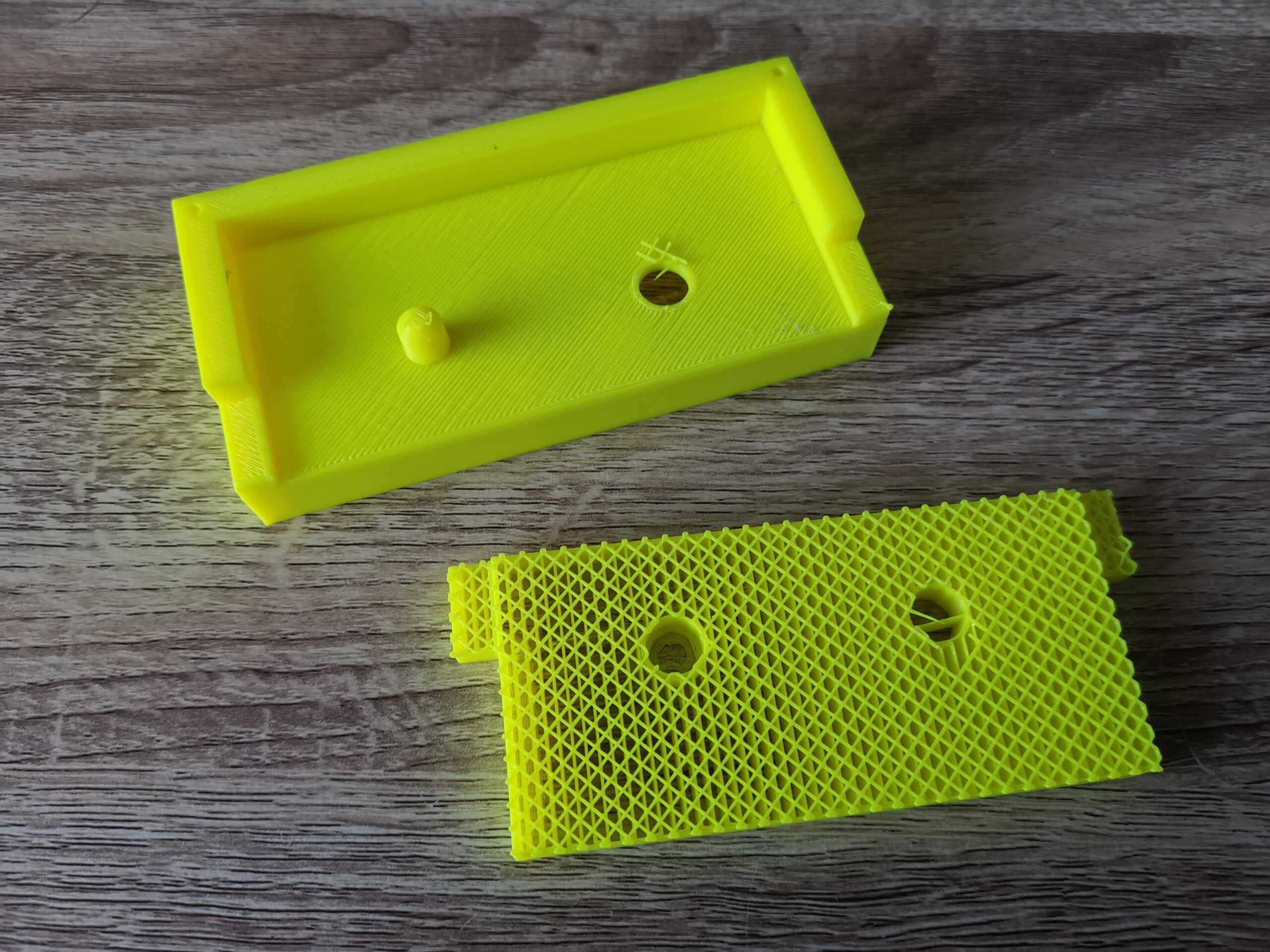
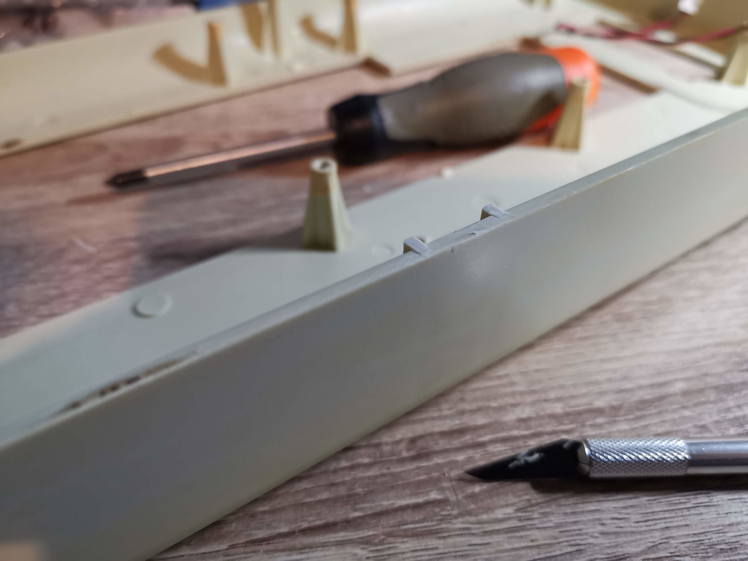
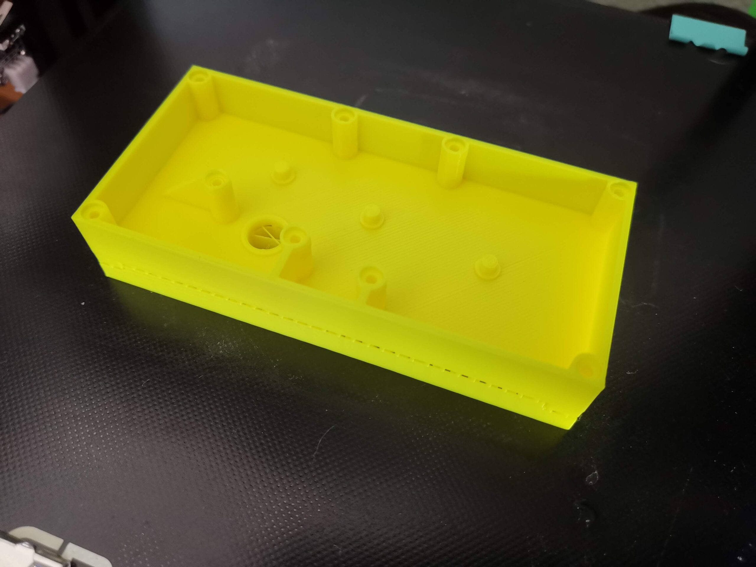
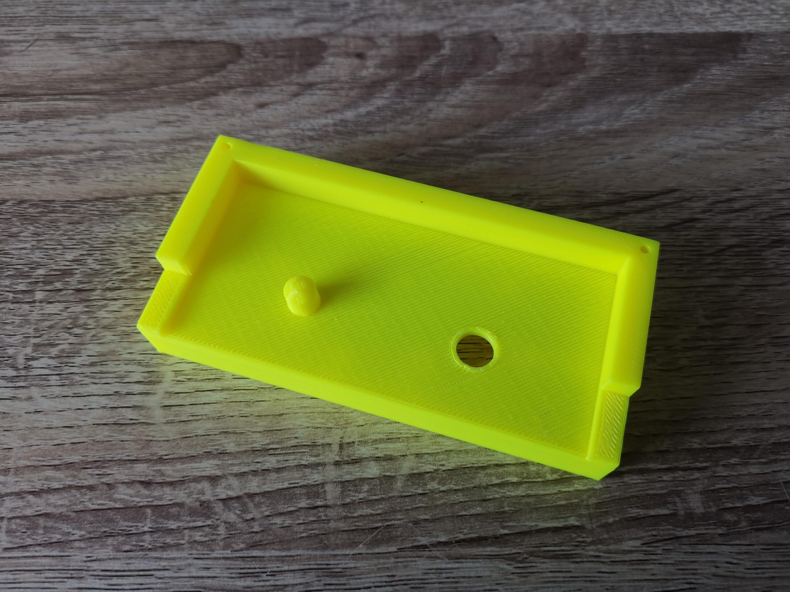
View showing the support material removed.
With the support material removed you can now see the winder start to take shape. In the above photo you can see the latticed support material too. It’s made this way to minimise plastic wastage and also allow it to be broken away easily. The fewer points of contact it has with the main build, the easier it is to break off.
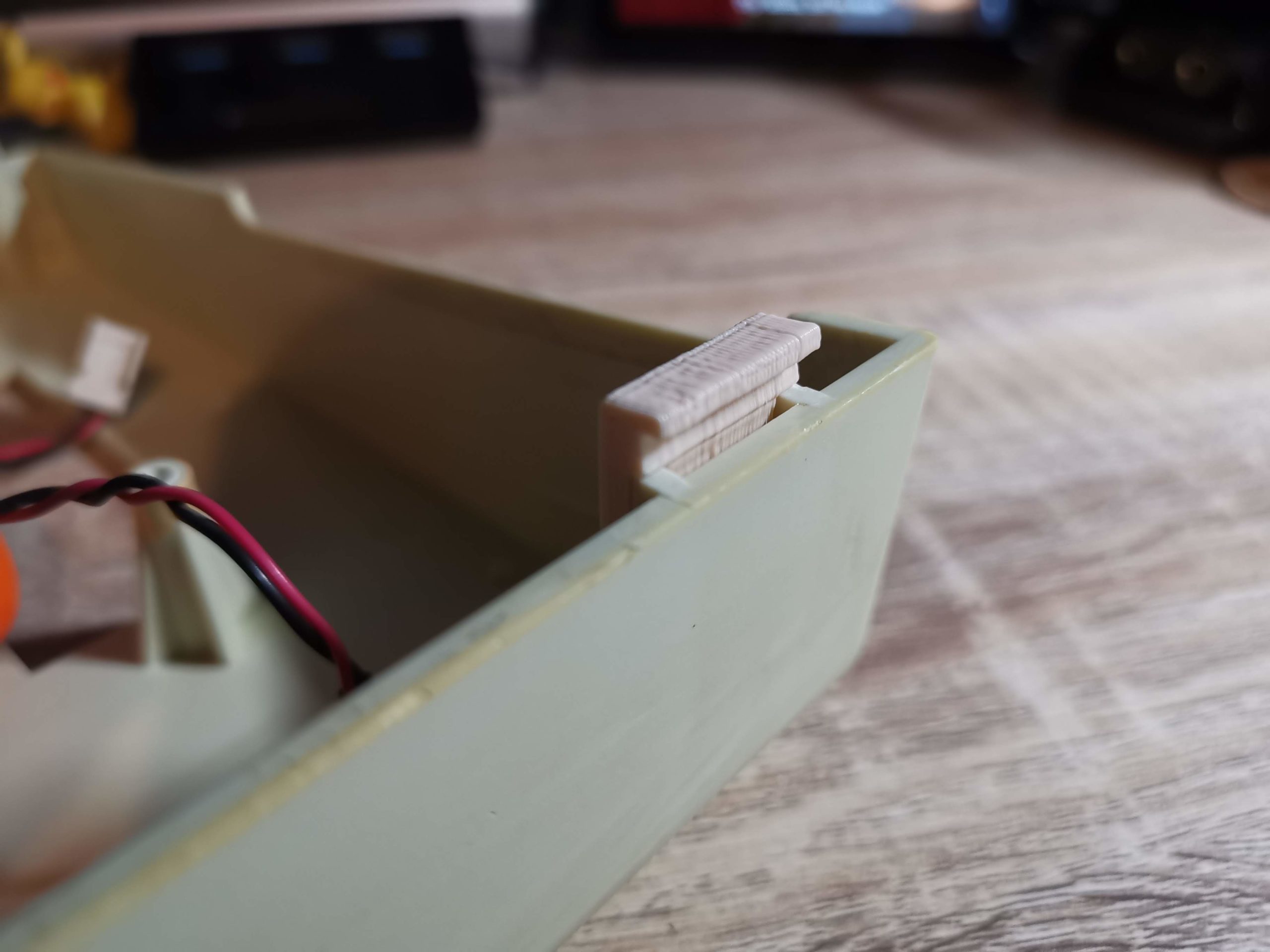
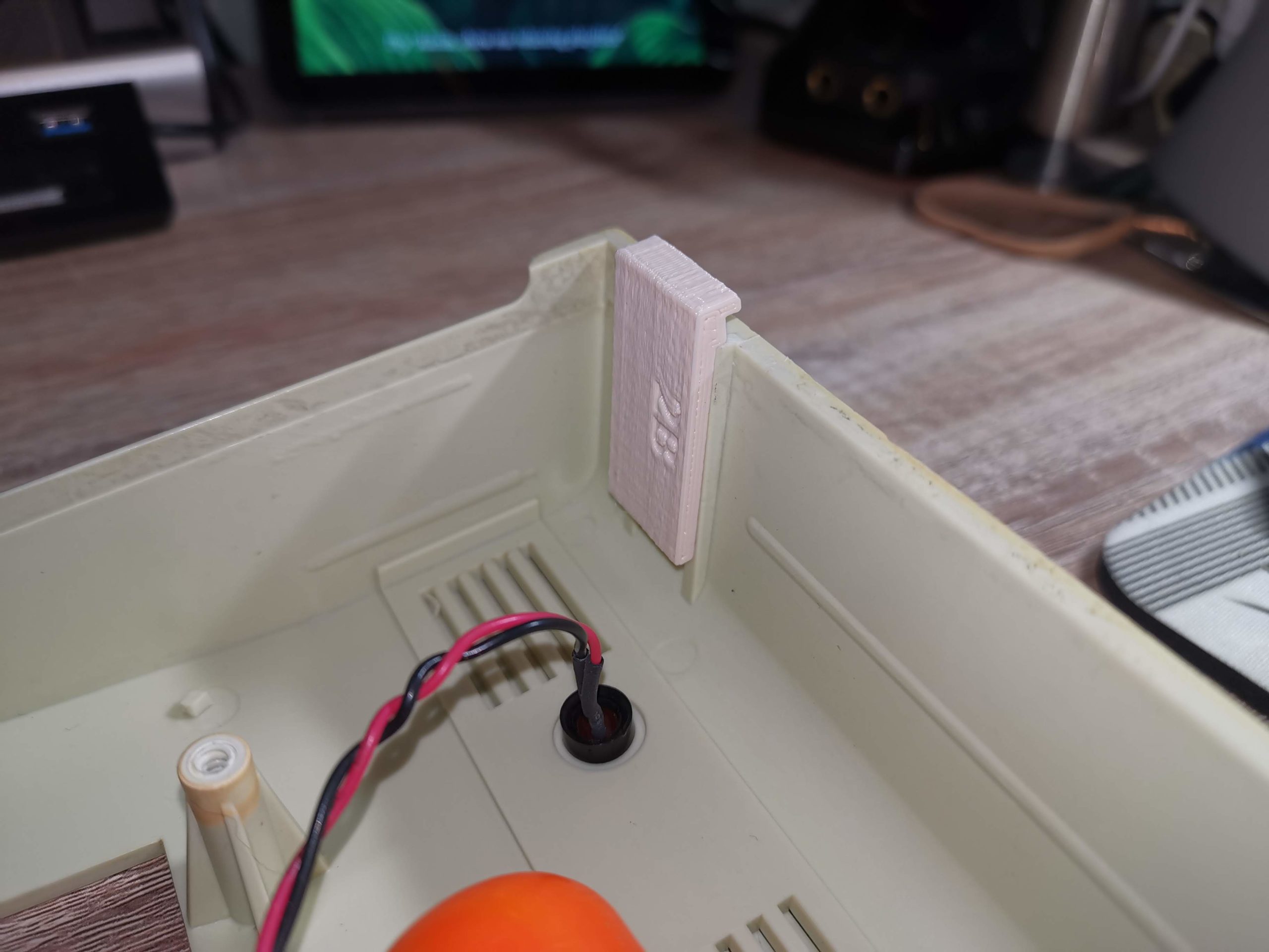
Here the few little pieces of support material that were clinging on have been removed with a craft knife.
In the above photo I have cleared away the few little straggly bits of plastic left by the supports with my craft knife.
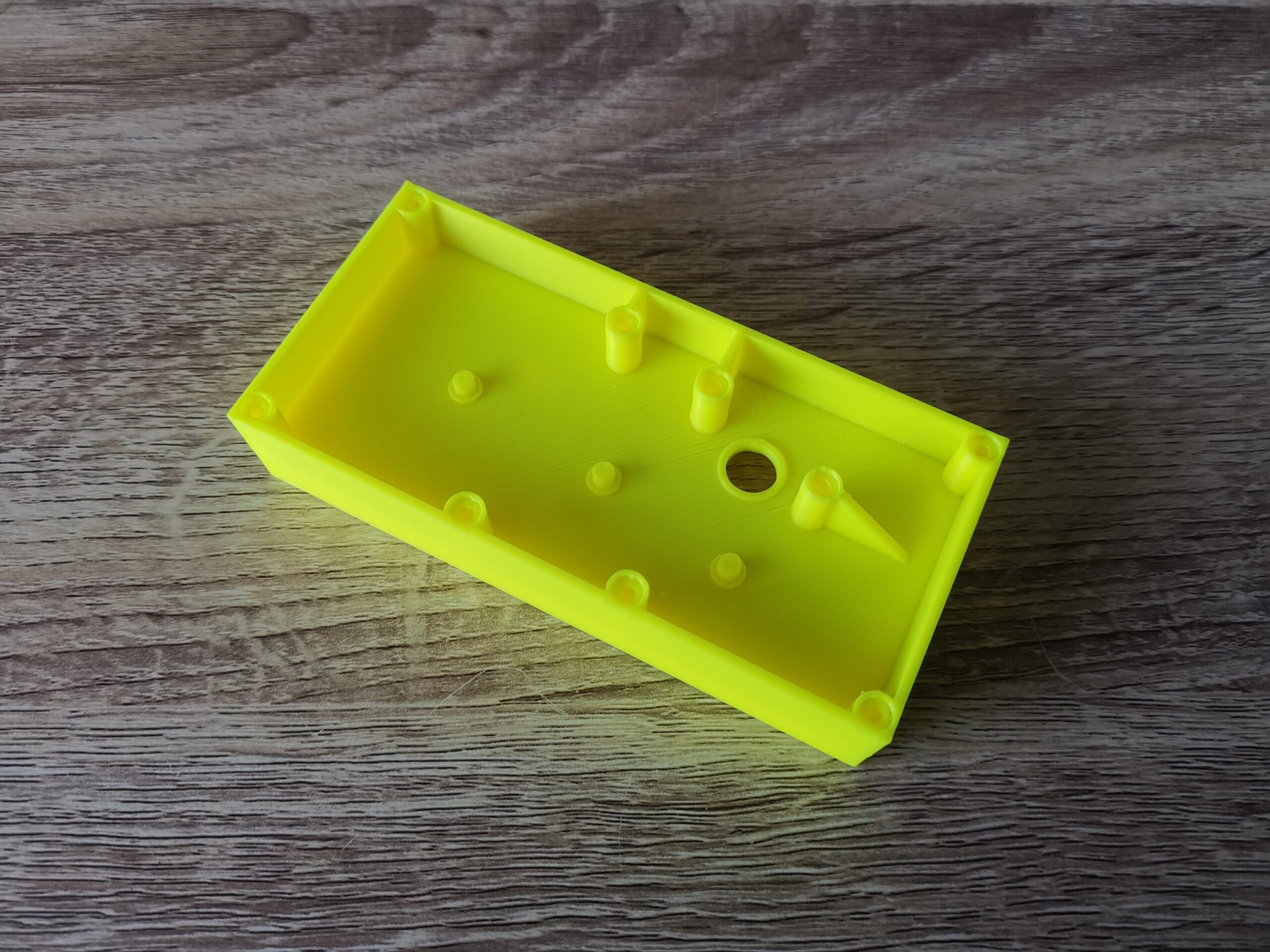
This is the case viewed from the other side.
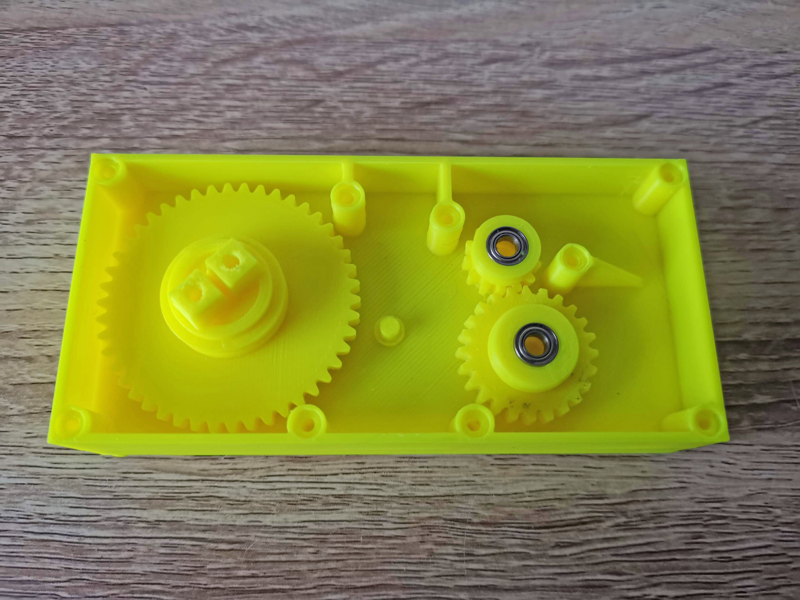
This is what the inside of the winder case looks like. There are 8 posts to support the case screws, a hole for the winder spool and 3 protrusions where the gears will sit.
Gathering the parts together
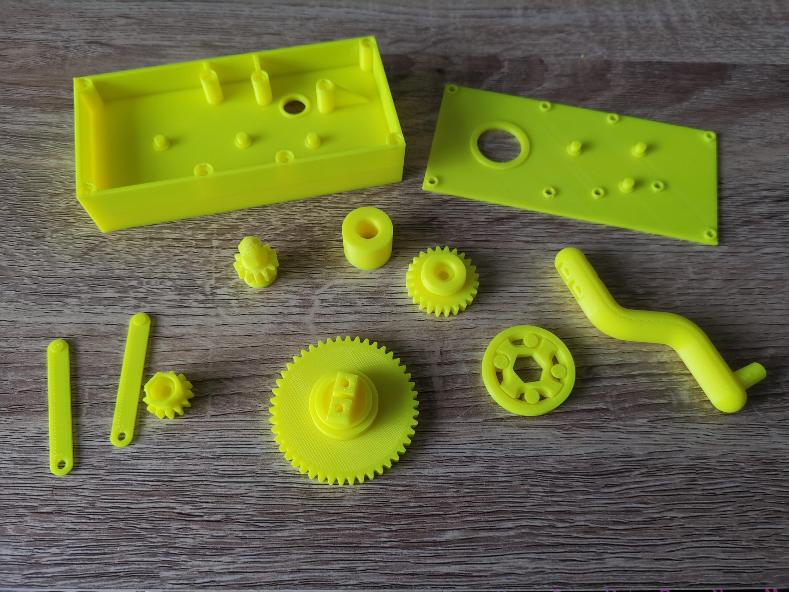
All the 3D printed components ready for assembly.
This photo shows all the parts of the winder fully printed a few days later. The instructions advise printing the cogs on rafts because they can be difficult to remove from the print bed. However I didn’t bother… I have glass bed and things pop off very easily once it cools down. It also means the finished prints are smooth and clean but of course YMMV. I did use supports for everything where the instructions recommended to do so and carefully removed them after printing.
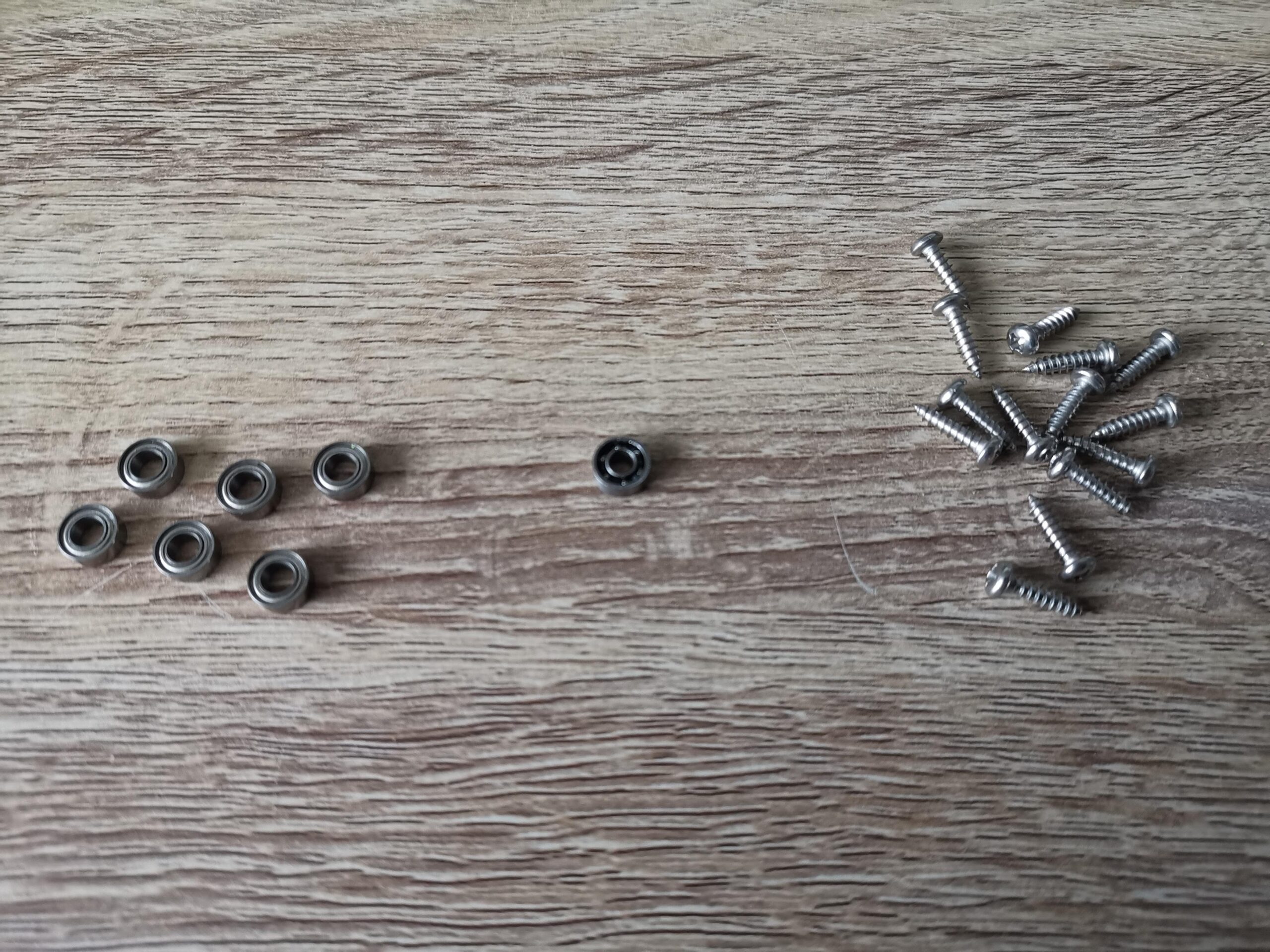
The bearings and screws needed.
What you will need
In addition to the 3D printed parts a few bits of hardware are also required. Some bearings, screws and a rubber belt. Here’s a rundown:
- 6x 4x8x3 miniature ball bearings for the gear wheels – I used these.
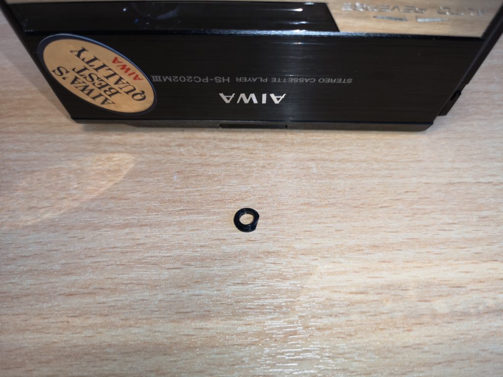
- 1x 3x8x3 miniature ball bearing (for the winder knob) – I used these.
- 14x 3x12mm pan head self-tapping screws – I used these.
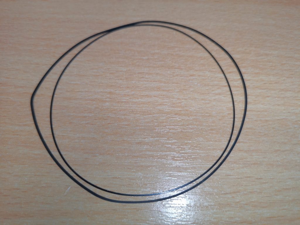
- A 1mm square rubber belt approximately 55mm in diameter.
- Philips screwdriver.
- Craft Knife.
- Side cutters (to help remove support material if necessary).
- Silicone Grease (optional but recommended).
- 3D printer!
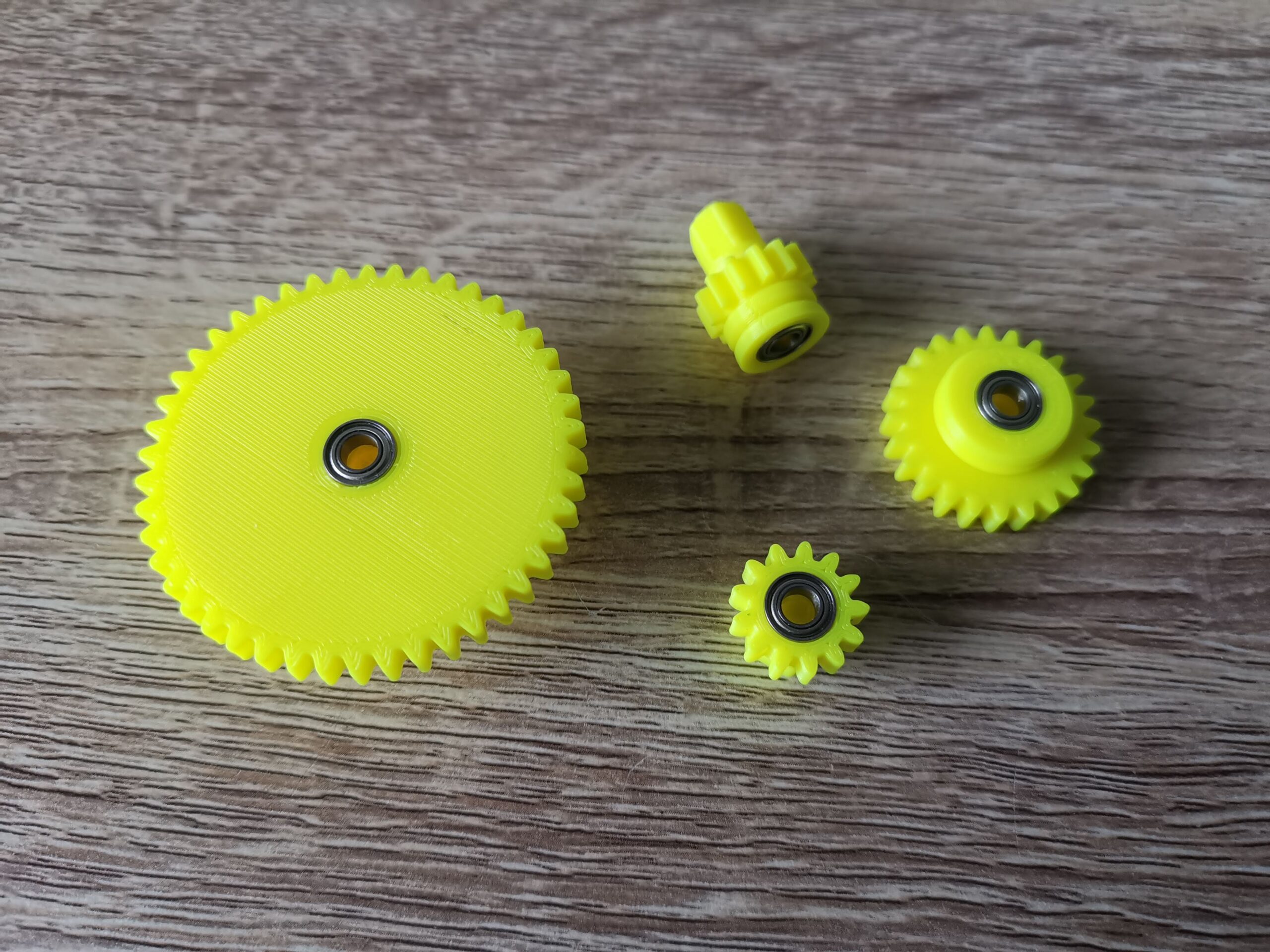
Gears with bearings fitted.
The next step was to fit the 6 bearings into the gear wheels. The two pulley cogs are fitted with two bearings, one each side whilst the driving gear and spool take just one.
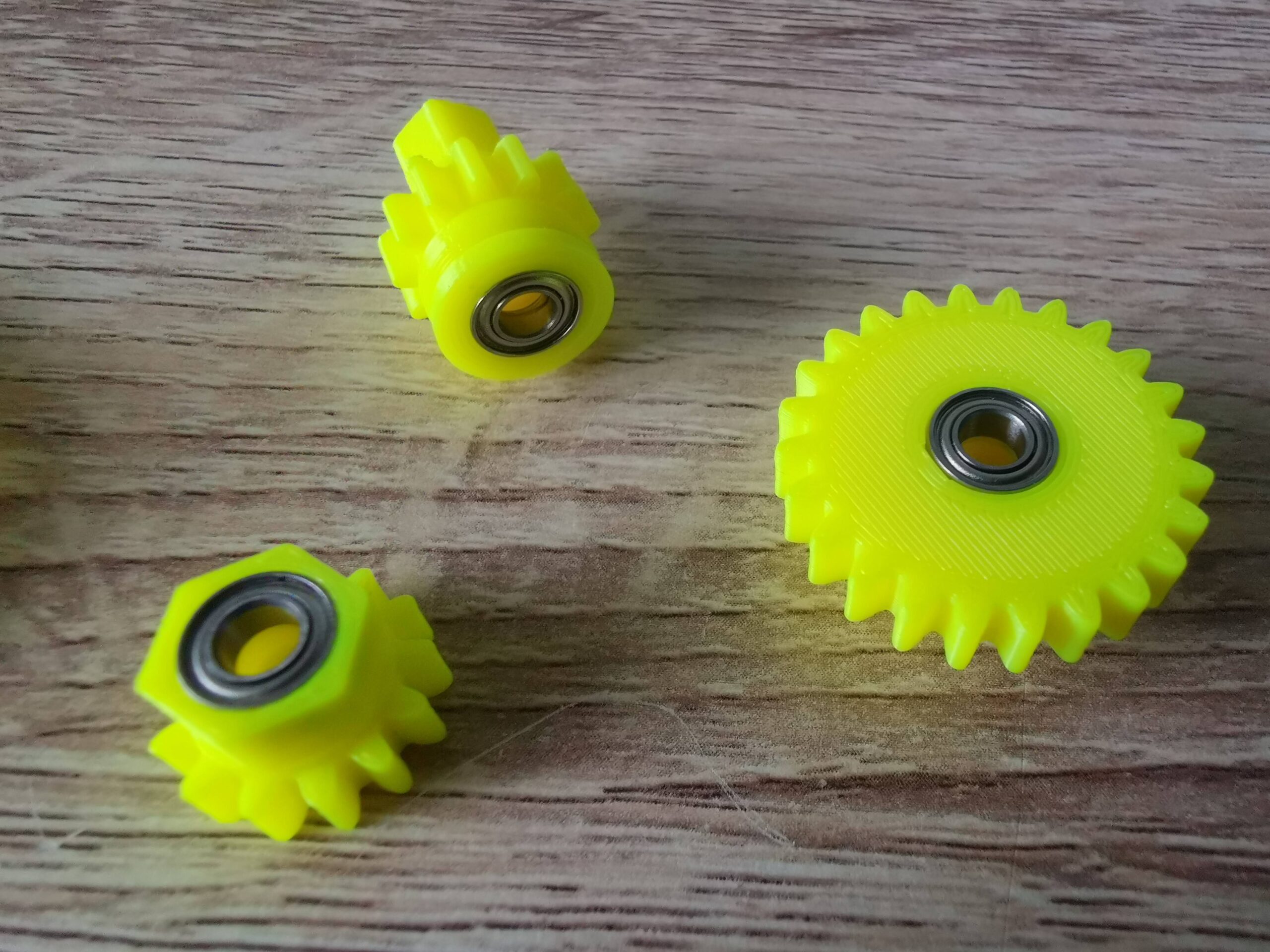
Gears with bearings fitted.
The bearings were a snug fit but I didn’t have to force them in at all. Once fitted they remained in place by friction alone so there was no need to glue them in.
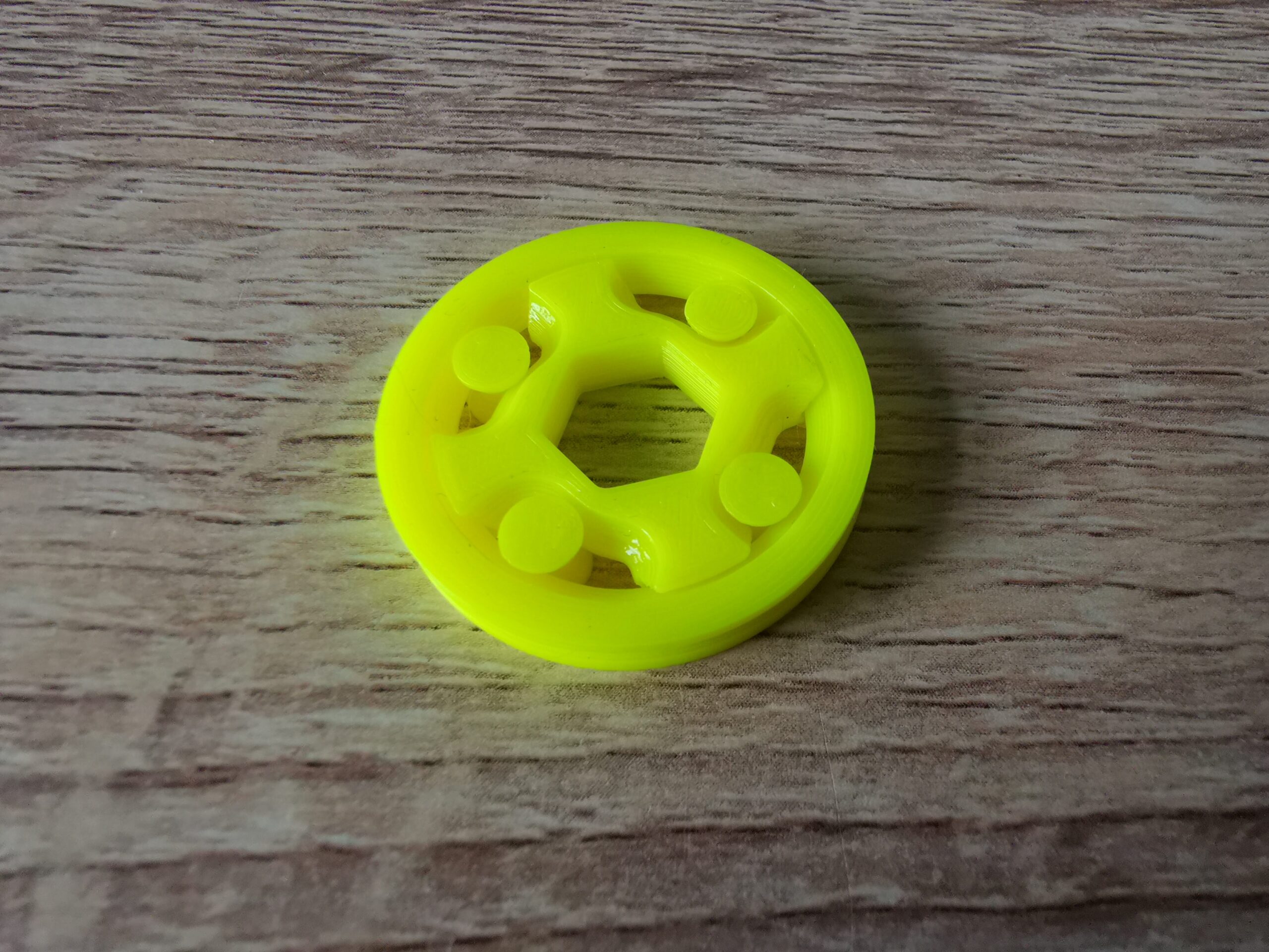
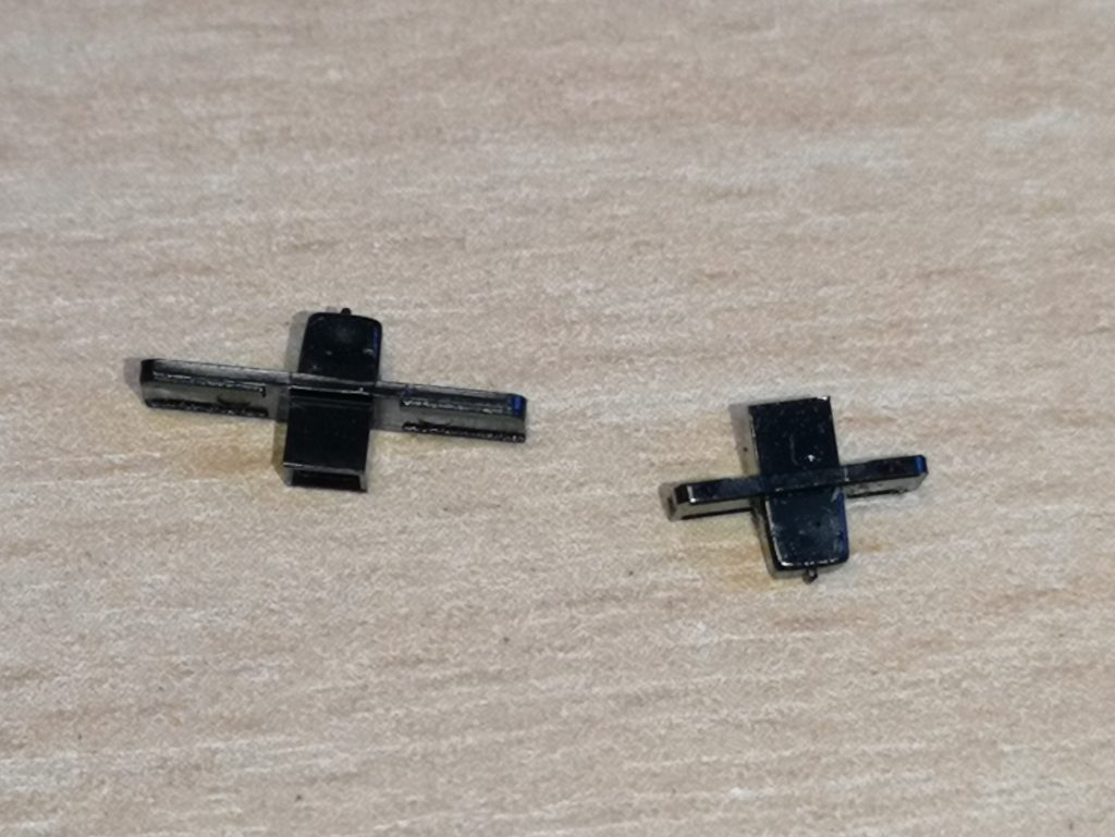
One-way clutch.
The winder incorporates an ingenious little one-way clutch mechanism that will only rotate in one direction. The benefit of this is it prevents you from accidentally winding a tape in the wrong direction causing it to unspool inside the case. Impressively it prints in situ too – there are 6 moving parts which are all printed as one complete mechanism together.
Putting it all Together
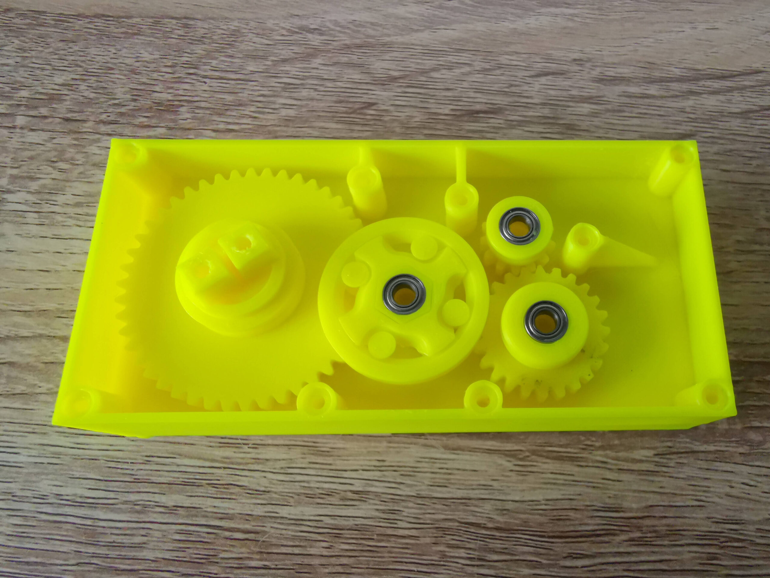
Start with these gears first.
Next came the exciting part – putting it all together. The driving gear, both pulley’s and spool went in first, making sure the bearings all seated correctly on the pegs.
Then add these. Note that pulley 1 and the clutch have already been assembled in this photo.
Next to go in was the one-way clutch which fitted onto the hexagonal shaft of pulley 1. It can fit either way around but needs to installed so that it ‘sticks’ when turned anti-clockwise but free-wheels clockwise. The instructions said to glue this in position but I didn’t bother as its going nowhere once the lid is attached.
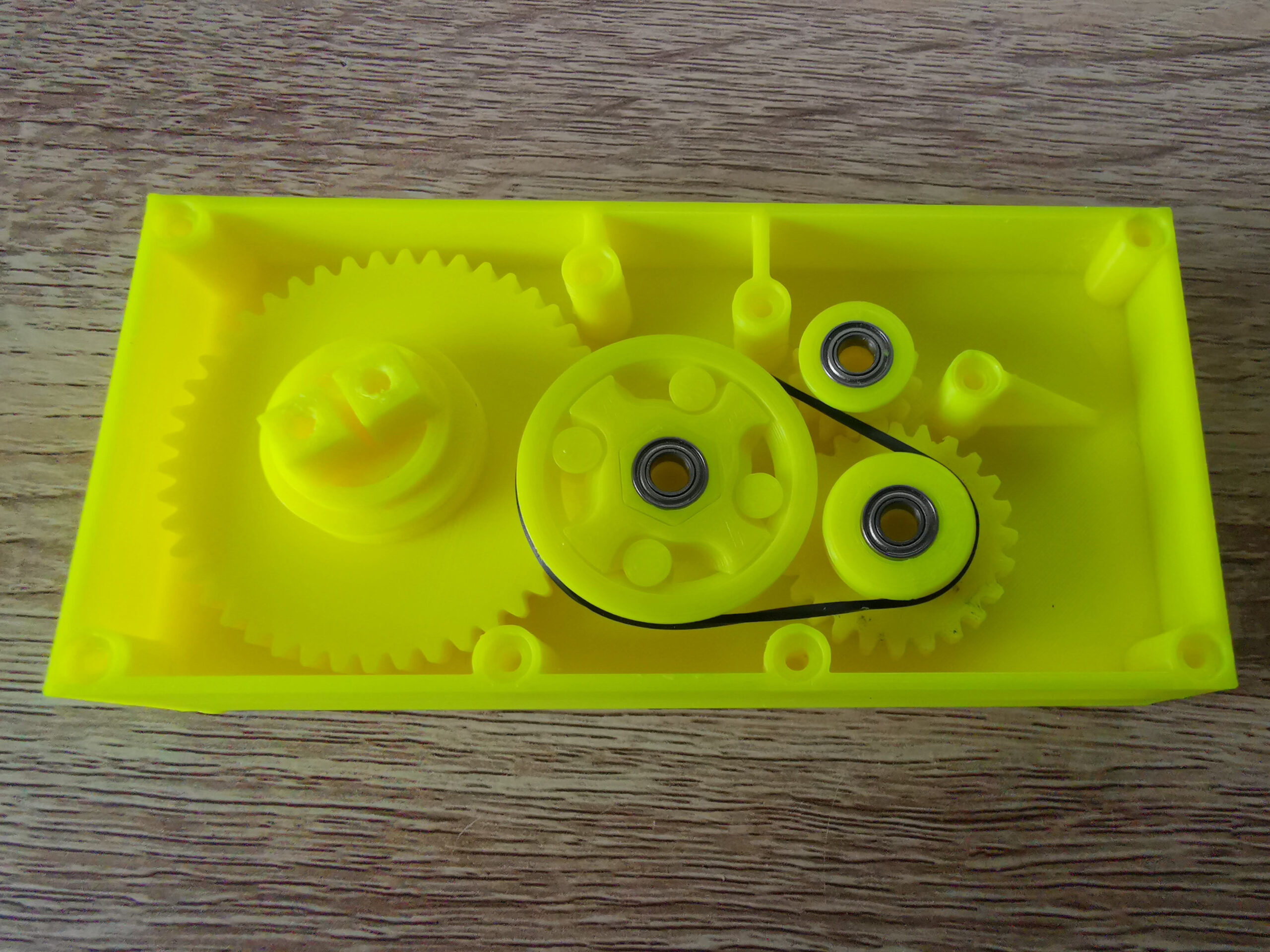
The rubber belt is added last.
The belt went in next and simply needed stretching around the clutch and pulley 2. There was a fair amount of tension here with the clutch being pulled over to one side, however once the lid goes on and the pegs slot into the bearing top and bottom, it sorts itself out.
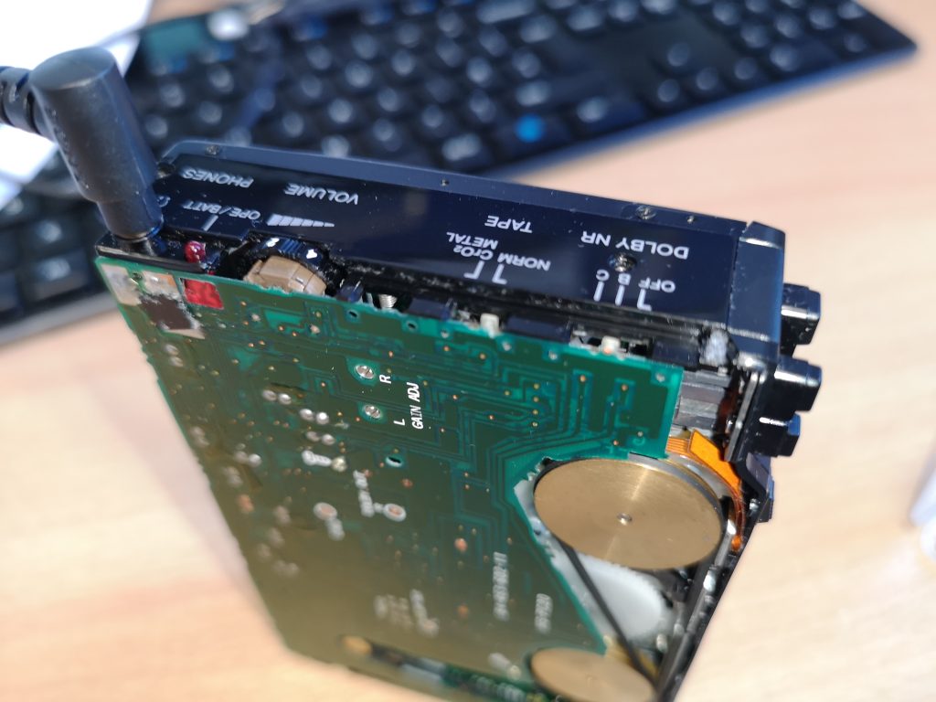
A minor issue…
I did have one issue at this point when putting everything together. There was too much friction with the spool and it wasn’t turning freely. I tried shaving/filing plastic from the cog teeth, adding a drop of oil to the bearing and adding a little silicone grease to the teeth but none of this really helped.
In the end I reprinted the part scaled down slightly to 98% which allowed the spool to spin freely. I also had to enlarge the bearing recess slightly with a Dremel so the bearing would still fit inside. Possibly if I’d persevered a little longer with the file I could have got the original part to work. However given how everything else fits together perfectly I figured the part needed re-designing slightly for a better fit. Regardless, I’m happy with my fix and how it now operates.
Before I screwed the back cover on I also added a tiny bit of silicone grease to the other gear wheels just to help keep them lubricated.
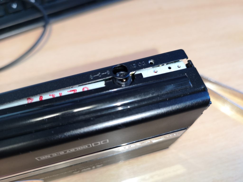
The Finished Winder
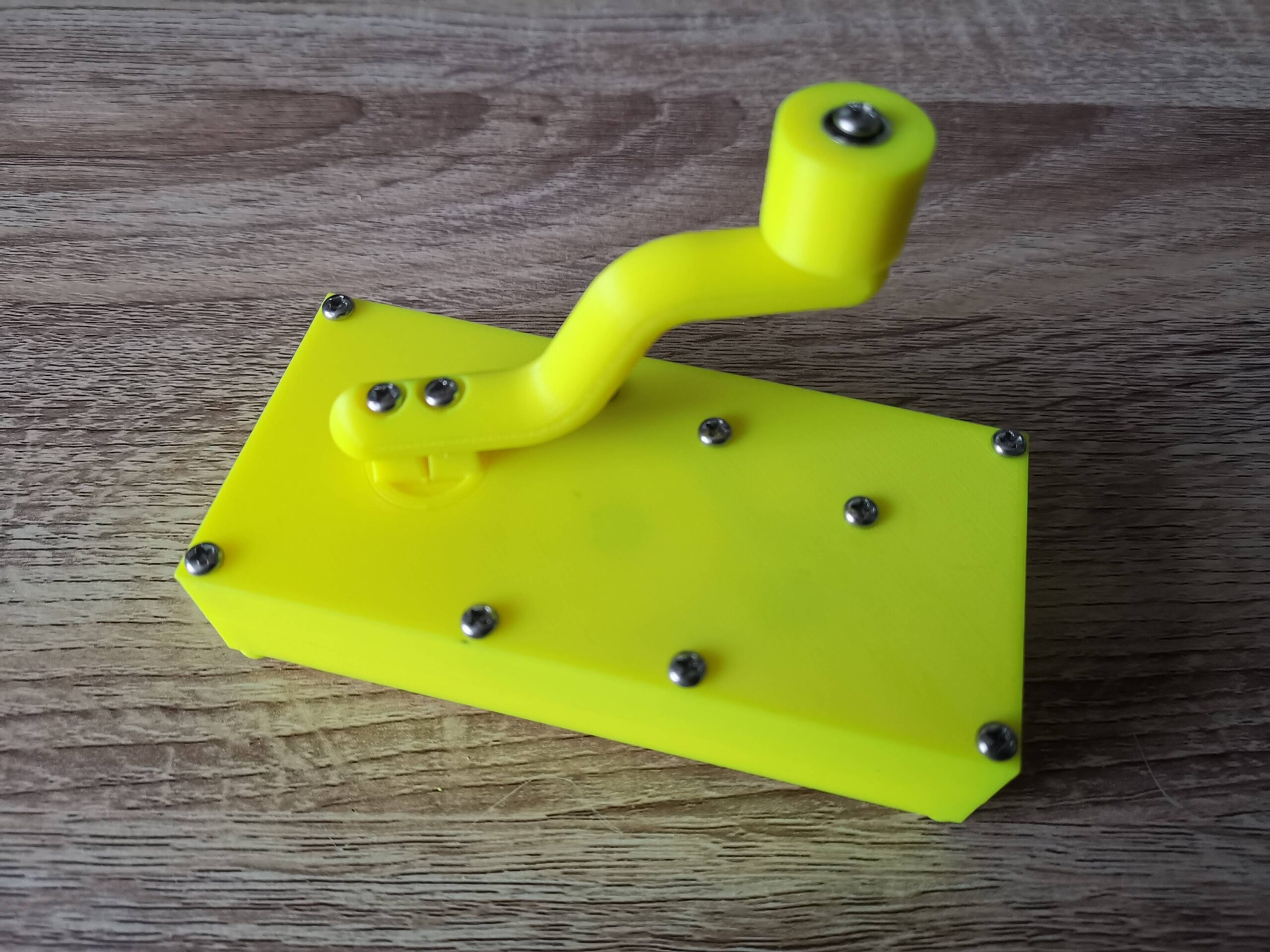
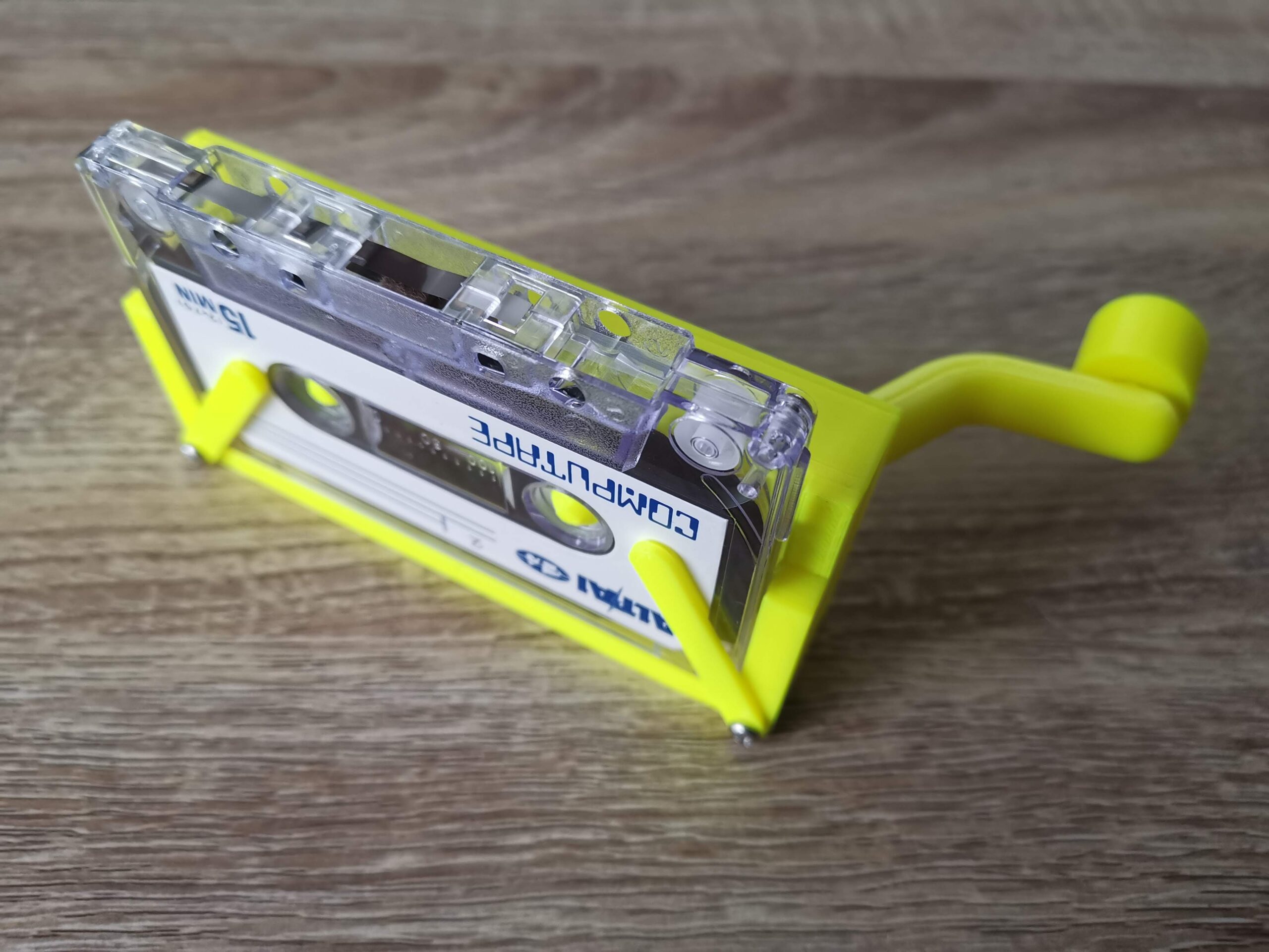
View of the back of the assembled winder.
Here’s the winder with the back screwed on and the handle and knob attached. The knob also has a bearing inserted into it so that when it’s screwed to the handle it will still spin freely.
I had no issues screwing things together but the instructions did advise caution in case the plastic splits and suggested drilling out the holes further as a precaution. Again I didn’t bother as I felt my screws were a good fit for the holes but again YMMV.
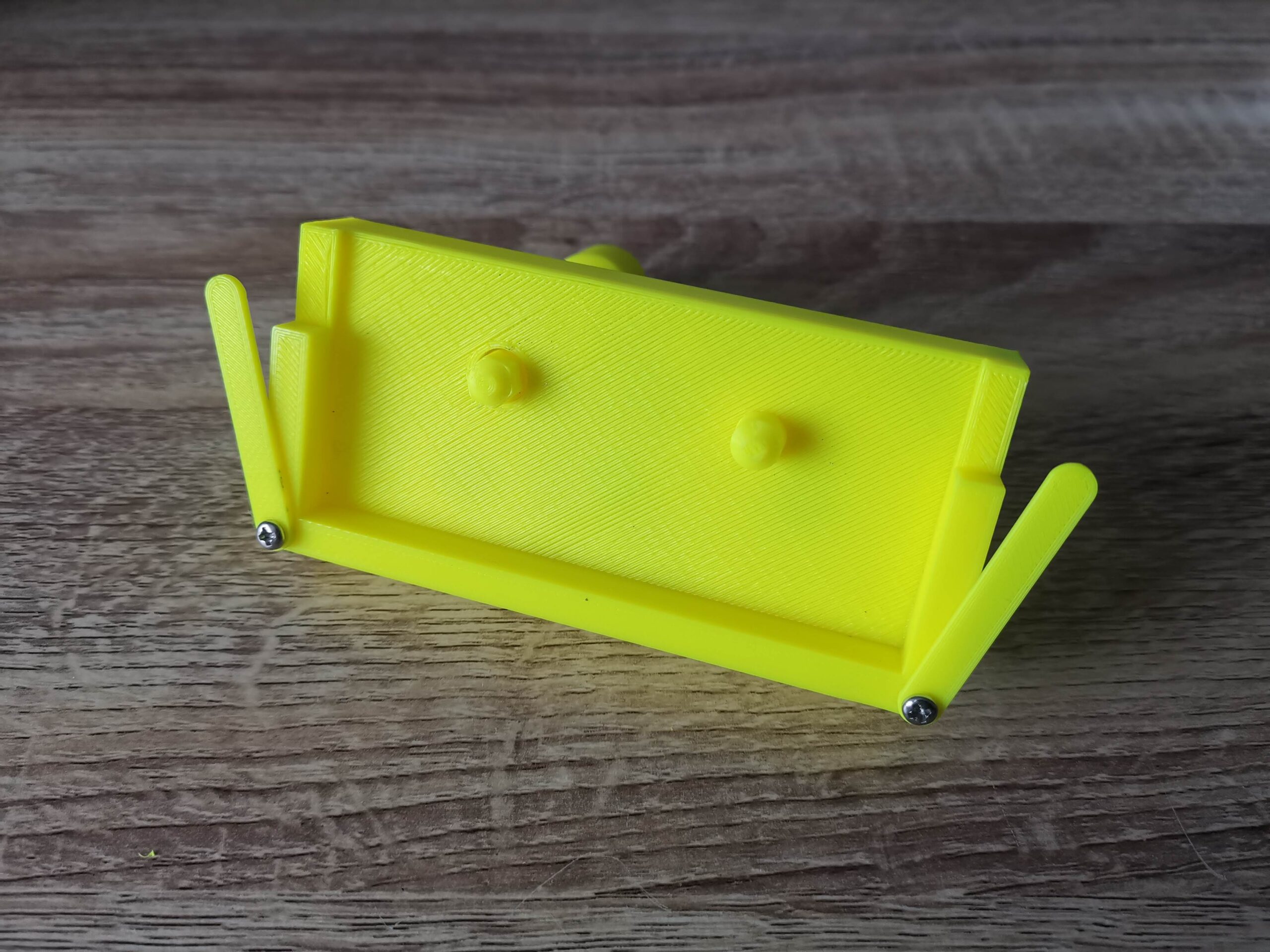
Front of Winder with retaining clips attached.
The two retainer clips attached to the front of the case using a couple more screws. The dimples are positioned such that they face the back of the winder.
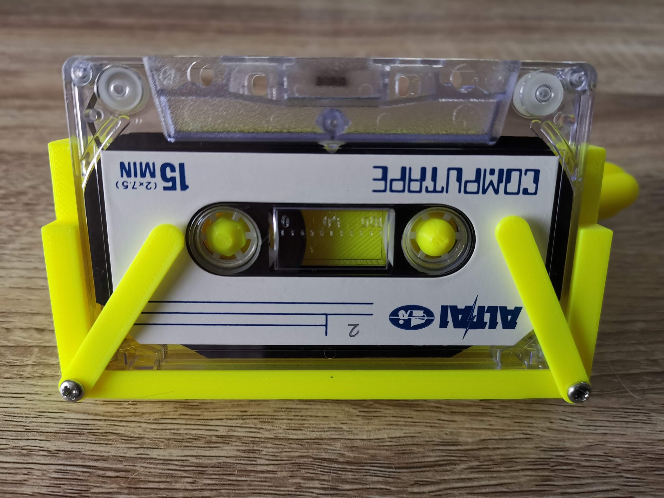
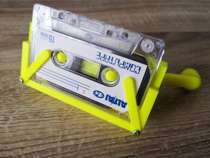
Tape held captive by retaining clips.
The screws need to be tightened just enough so that the clips can move with a little force but remain in any position. These are used to hold cassette tapes securely in place whilst winding.
View of the winder looking down.
Video of winder in use
And here’s the finished winder. I have to say it works extremely well and will be a great help in minimising wear and tear to my various C2N Datasette’s, Walkman’s and tape decks. It’s fast too, I managed to rewind a C90 tape in around 30 seconds. The use of a belt helps to ensure that when reaching the end of a tape, any excess force results in the belt slipping rather than damaging the tape.