Lyonsden Blog

Category - How to’s

Amiga 500 Super Denise Upgrade

The A500 machines shipped with a graphics chip called ‘Denise’ that is responsible for handling sprites and also all the different screen modes and resolutions you can use with Workbench and other apps. The later Amiga 500+ model sported an updated chip called ‘Super Denise’ which offered quite a few more screen modes and resolution options. The Amiga 500 Super Denise upgrade is a very straightforward modification which simply involves getting hold of the newer chip and replacing the old one with it. (It is an exact pin-for-pin replacement). For more detailed info on the Denise chip look here.

Getting hold of a new chip

The ‘Super Denise’ has the chip number 8373-R4 whereas the old regular ‘Denise’ is 8362. You can usually pick up Super Denise chips on eBay – here.  I paid around £20 for mine which I though was fair… be patient and wait for one at a fair price – don’t get ripped off.

Removal & Replacement of the chips

You can remove the the old chip with just a small flat bladed screwdriver if you are careful. Just lever up each end slowly, alternating from one end to the other, making sure it lifts evenly from each corner so that the pins don’t bend. Ideally though, use an ‘IC Extractor’ – it makes the job a lot easier and is a useful tool to have in your retro computer toolkit anyway. Again these are readily and cheaply available on eBay – here. The new chip should just plug straight into the socket. Make sure the marked end of the chip matches up with the notched end of the IC socket. If it goes in the wrong way around it won’t work and may even damage the chip and/or the motherboard. If the pins don’t quite line up you can bend them gently into place using a pair of pliers.

Amiga 500 Super Denise Upgrade – In Pictures

Below you can see before and after screens showing SysInfo details, and available screenmodes along with the two different Denise chips fitted. The end result is a success with more screenmodes (eg Super-Hi Res modes) available straight away, even with my standard 1084S monitor. However in order to benefit from the rest of the modes the Super Denise chip offers (such as Productivity) I need to get hold of a proper Multi-Sync monitor that can handle the different refresh rates they need.

Amiga 500 Super Denise Upgrade

Sysinfo Screen with Standard Denise Fitted

Amiga 500 Super Denise Upgrade

Screen Modes Available with Standard Denise Chip

Amiga 500 Super Denise Upgrade

Standard 8362R8 Denise Chip Fitted

Amiga 500 Super Denise Upgrade

Replacement 8373R4 Super Denise Chip Fitted

Amiga 500 Super Denise Upgrade

Sysinfo Screen with Super Denise Fitted

Amiga 500 Super Denise Upgrade

Screen Modes available after fitting Super Denise Chip

Repairing a Roctec Floppy Drive for an Amiga

Repairing a Roctec floppy drive

This is a guide to repairing a Roctec floppy drive for an Amiga 500 computer.  I thought I’d write this up as much for my own benefit as other peoples so I can refer back to it in another 20 years! LOL.

Roctec Amiga external floppy drive

Roctec Amiga external floppy drive

If you ever pop a disk in your external Roctec drive and hear a strange whirring noise and can’t read any of your disks then the chances are you are suffering from a perished or broken drive belt.

Perished Drive Belt

Perished Drive Belt

These drives use a rubber belt to connect the drive motor to the spindle hub. The rubber belt only has a finite life and given most of these drives are getting on for 30 years old now it’s hardly surprising that they expire.

cof

No tension in old perished belt

The good news is that it’s pretty easy to replace them and I’ll give an overview of what you need to do here.

Getting Started on the Repair

The first thing you need to do is undo the 6 screws on the underside of the drive case using a small philips screwdriver.

Underside of drive case

Remove these 6 phillips screws.

This particular drive case is made from a solid metal rectangular tube so you need to slide the floppy drive out. The aim here is to slide everything out of the BACK of the case. The first step is to gently slide the floppy drive forward out of the case far enough to detach the plastic fascia from the front of it. Unless you do this it won’t slide right into the case and out the back. There are 2 small tabs on each side of the fascia which you can gently bend with a small flat-bladed screwdriver and it will pop right off. Don’t force anything or it will break – it should come off easily.

Drive Fascia removed

Drive Fascia removed

Now you need to prise the back part of the drive out of the case using something thin enough to slide into the tiny gap between the case and the backplate, I found the blade of my pocket knife to be perfect for this but be careful not to injure yourself or damage the plastic/paint on your drive! Once you’ve got it moving slide it out slowly (a slight side to side wiggle can help here). It will be attached to the floppy drive via a ribbon cable so keep going until you’ve got the floppy drive out too.

Roctec floppy drive detached

Roctec floppy drive detached from controller board

The floppy drive has a thin metal cover that protects the mechanical innards and it is held in place by some little tabs on the edges and a solitary screw at the back right (when viewed from the front).

Roctec Floppy Drive Rubber Belt Path

Roctec Floppy Drive Rubber Belt Path

Replacing the Belt

Once the top is off you can see the drive mechanism, motors, heads and so on. Carefully remove what’s left of the old belt with a pair of tweezers. Be careful not to touch the drive heads with anything metallic or you may damage them. The photo above shows the path the rubber belt follows, indicated by the yellow line.

The next step is to remove the drive motor which is attached to a metal bracket that runs across the back of the drive. It is held in position by one screw in the far left corner and another on the right a few cm down from the corner. Don’t touch the two screws with the large flat heads either side of the motor. Be careful you don’t pull the bracket too much as there are two tiny wires connecting the motor to the circuit board here so be careful to support the bracket whilst you are handling the drive to replace the belt.

How to detach the motor and bracket

How to detach the motor and bracket

Drive motor and bracket removed

Drive motor and bracket removed

Once the bracket and motor are out of the way you can carefully thread a replacement belt around the large drive wheel, small tension wheel and keep a loop ready at the top right to go on the motor spindle. Follow the yellow path in the earlier photo and take your time as it can be a little tricky to get the belt into place. A small flat bladed screwdriver and a pair of tweezers are essential for this. Don’t forget the belt needs to thread behind the small silver pully wheel as this is what tensions the belt.

Close-up of the small tension wheel you need to thread the belt behind

Close-up of the small tension wheel you need to thread the belt behind

Once you’ve got it threaded around the wheels correctly you need to get the final loop onto the motor spindle. It helps if you grab the loop with some needle nosed pliers here and pull it taught with one hand whilst guiding the motor spindle into the loop with the other. Once this has been achieved (it may take a few goes as it’s quite fiddly) place the bracket back in place and rotate the large drive wheel slowly and check the belt stays on, is running where it should and isn’t fouling any components.

Look carefully through the tiny gaps in the top of the drive motor you should be able to see the motor armature slowly rotating as you move the belt. If it is then job  done, time to put it all back together! If it isn’t then don’t fret, just double check the belt is following the correct path, isn’t twisted anywhere and hasn’t slipped off any of the wheels.

Congratulations, your Roctec drive should now be fit for active duty for another several years now!

Upgrading my Amiga A500 to 1MB Chip RAM (1MB Chip RAM Mod)

1MB Chip RAM Mod

Introduction

My A500 motherboard is a Revision 6A which means that it is quite a straightforward modification to get a 512K trapdoor expansion to be seen as additional Chip RAM. The 6A comes with the Enhanced Chip Set (ECS) variant of the Agnus chip called ‘Fat Agnus’ which is able to support up to 1MB total Chip RAM. This 1MB Chip RAM Mod will combine the 512k onboard RAM with the 512k Trapdoor RAM to give 1MB total Chip RAM, just like you get in the later A500 Plus models.

Chip RAM is needed for stuff like graphics as it is the only memory that the custom Amiga chips are able to access and 512k goes nowhere! Opening Workbench windows, increasing the screen resolution, adding a wallpaper all gobble up precious Chip RAM. The popularity of WHDLoad as a means to run old Amiga floppy games off a hard drive is also a problem for 512k machines as most of the games require 1MB of Chip RAM to function.

Checking the Amiga board revision

You can check what revision your Amiga is by opening it up and removing the floppy disk drive. The revision number will be etched into a small area underneath along with other interesting information such as the serial number and when it was made. It looks like my board was designed in 1988 (30 years old this year!) but that it might have been assembled in 1989/90 going by the serial number sticker?


1MB Chip RAM Mod

Revision 6A motherboard confirmed


1MB Chip RAM Mod

Here’s a screenshot from SysInfo confirming the presence of an ECS Agnus chip – needed for this mod.

Under the knife!

The first thing to do is cut the small trace between the lower two pads (2 & 3). I used a small craft knife but any similarly sharp knife should do the job. Be very careful not to slip with the knife as there are several other tracks on the motherboard that you do not want to damage! To check that you have successfully cut the track you can use a multimeter – there should be no continuity between the two pads if the track has been cut properly.


1MB Chip RAM Mod

JP2 – Track cut between the lower 2 of the 3 solder pads with a sharp craft knife.

Bridging the gap

After successfully cutting the track between pads 2 and 3 the next task is to solder the top two pads (1 and 2) together. I found the easiest way to do this was just to keep adding blobs of solder to one of the pads until there was enough to drag across to the other pad and bridge the gap.


1MB Chip RAM Mod

JP2 with pads 1 and 2 soldered together.

The shortcut

Traditionally the next part of this modification required cutting a track on JP7A but just by chance I stumbled across an advert for a 512K Trapdoor expansion on eBay that bypasses this requirement completely. This particular RAM expansion has a series of jumpers on it that you can use to enable/disable a number of features including using it to expand Chip RAM. It also features a clock with battery backup so it’s a very complete little package. Anyway, in order to have the 512k of RAM added to the pool of Chip memory you need to remove the blue jumper – this basically has the same effect as cutting the track on JP7A.


512K RAM Expansion

512K RAM Expansion with blue jumper disabled to enable it to be seen as Chip RAM.

Testing

The final step (after putting everything back together of course) is to turn on the Amiga and check that it now has a full 1 megabyte of Chip RAM.  Easiest way to check for sure is to load up good old SysInfo and go to the Memory Information screen and you should see 1.0MB Chip RAM displayed. Job done!


SysInfo 1MB Chip RAM

SysInfo screen confirming 1MB of Chip RAM 🙂

Adding Bluetooth Audio to a Range Rover Sport Mk1

Ranger Rover Sport Bluetooth Audio

If, like me, you were disappointed to discover that your beautiful, highly specc’d Range Rover Sport Mk1 did not come equipped with Bluetooth Audio then I have a solution for you that will cost less than £20. Once you’ve got hold of the kit the whole job should only take you about 5 minutes.


range-rover-sport-mk1

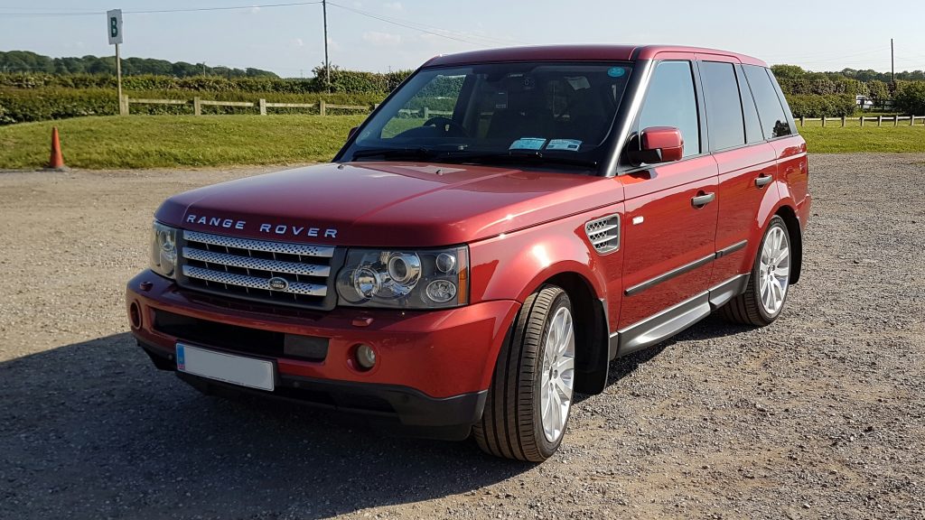
Mk1 Range Rover Sport


What you need to buy…

The first thing you need to purchase is a USB car charger adaptor for your rear cigarette lighter socket. The more slimline the better, I used this one which works really well. In fact I’ve got one of these in my front power socket too!

Next you need purchase yourself this little gadget from Amazon which is a bluetooth audio receiver and will convert your bluetooth audio back into good old analogue for your Range Rover sound system to play.

UPDATE: You may want to check out a new, alternative Bluetooth option I recently discovered at the end of this article as it offer a few advantages, albeit at extra cost.


Once the above gizmos have arrived follow the super-easy instructions below to enjoy wireless music playing in your car.


Bluetooth Adaptor

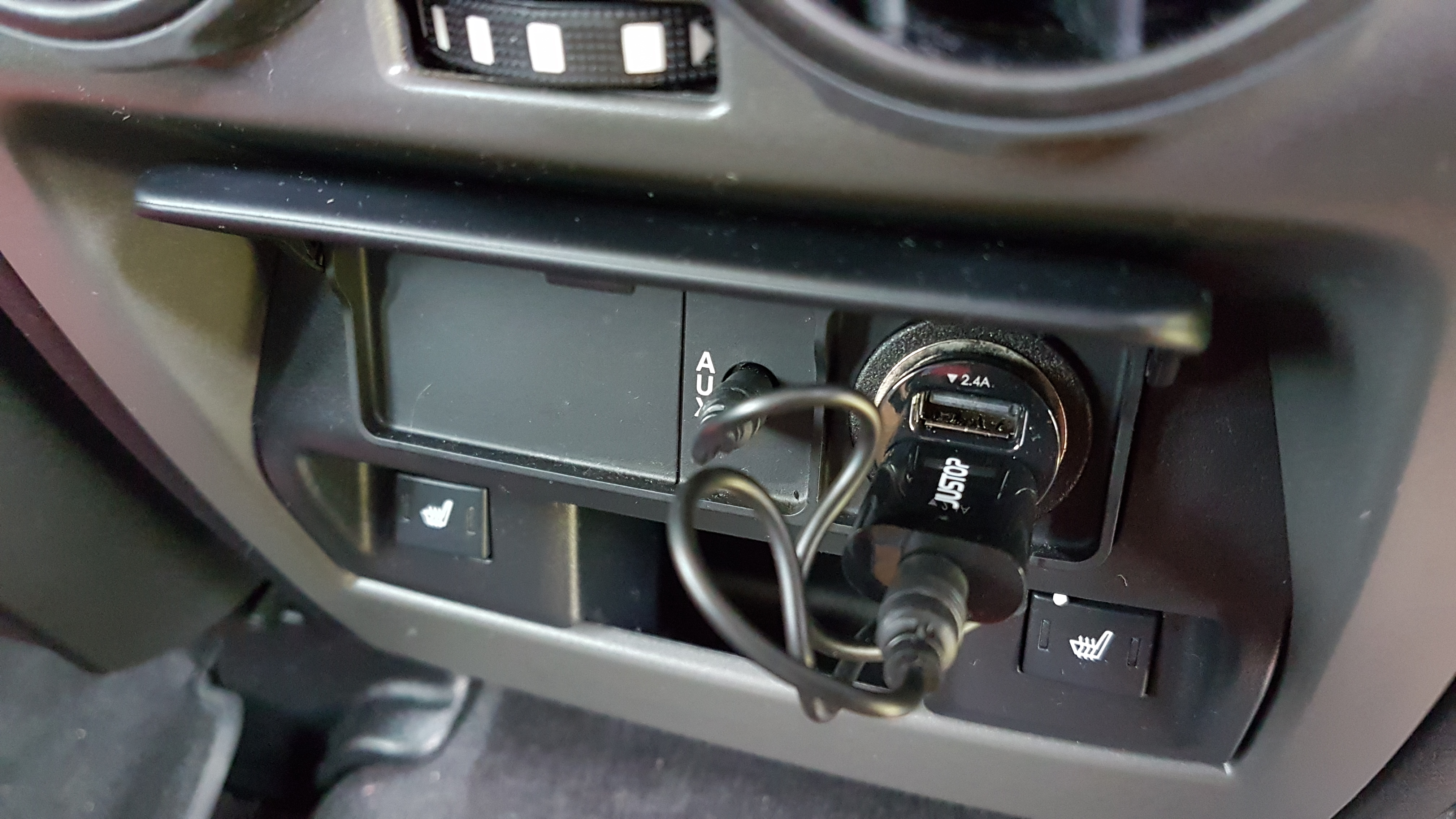
Bluetooth Adaptor connected to Aux rear aux socket


Installation…

First off you need to plug the USB adaptor into the rear passengers power socket (it hides underneath a flap on the centre armrest). Now plug the Bluetooth receiver into that USB adaptor . Finally you need to plug one end of the (supplied) auxiliary audio cable into the socket on the end of the Bluetooth adaptor. Plug the other end into the aux socket on the back of the centre armrest, located just to the left of the power socket. That’s it for the hardware side of things, the next step is configuring your phone.


Android Bluetooth Screen

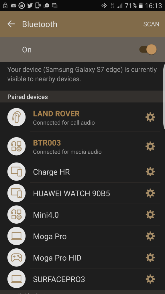
Screenshot showing Bluetooth adaptor paired.


The next stage of the install requires your backside in the drivers seat and turning on the ignition. Get your phone out and go to the ‘Add Bluetooth devices’ part of the phone settings. I have tested this with both an Android Marshmallow Galaxy S7 and an Android Nougat Huawei Mate 9 with no issues, although the settings on all phones will probably look a little different. (UPDATE: Have also tested with Android Oreo and Pie and on two more devices; a Huawei P20 Pro and a Huawei Mate 20 X). I see no reason why this wouldn’t work for an iPhone/iPod but I don’t have access to any Apple stuff so can’t guarantee it. I’d be very surprised if you had an issue though.

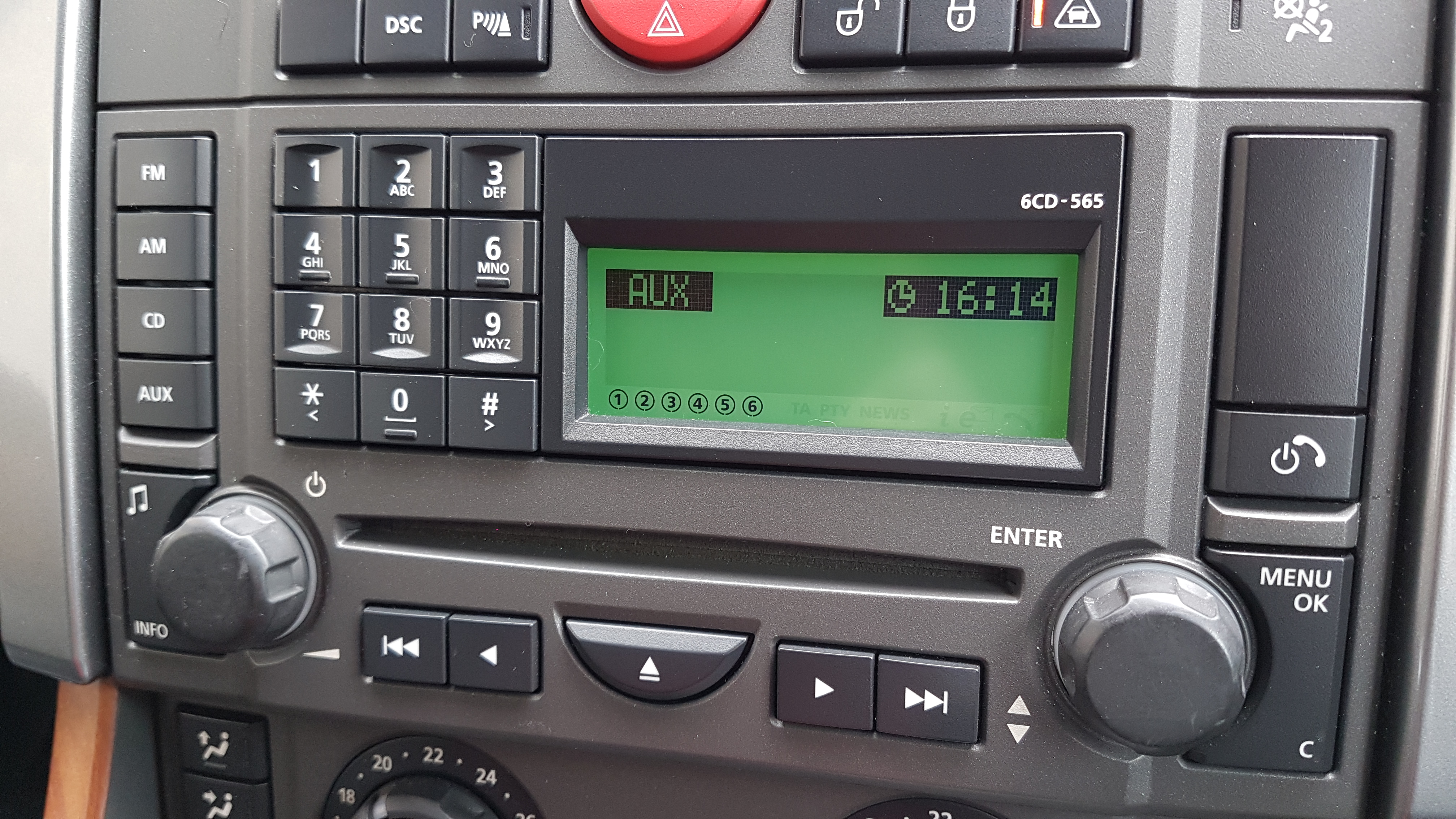
Once you have got to the ‘add Bluetooth devices’ screen, make sure your bluetooth is turned on and wait for the device ‘BTR003’ to appear. This is the bluetooth adaptor – add it as a paired device (there is no pairing code) for ‘Media Audio’ ONLY and you should be good to go. Turn on your Range Rover sound system and select AUX as the input and play some music on your phone and it should come through loud and clear! I find the AUX input a little on the quiet side compared to the CD and Radio but you can easily compensate by turning the volume up on your phone and/or the sound system itself.

Every time you get in your car and turn on the ignition your phone will automatically pair with the bluetooth adaptor so you should never have to mess with the settings again – it’ll just work. Your phone will still work for bluetooth handsfree calling through the car phone as that uses a separate ‘Call Audio’ bluetooth connection.


Aux Input

Range Rover Stereo Aux Input


Have fun and if you find a better way to do this or have any questions please contact me!

I know it’s not a perfect solution as the adaptor does stick out a few cm and if you have kids in the back it may not last long… but as it’s just me and the wife in our car I’ve not had a problem so far…

UPDATE: May 2019

OK so I wrote this article a few years ago now and the above solution has continued to work well for me. I’ve changed phones a few times since then (I currently have a Huawei Mate 20 x) and it worked with each and every one of them. However recently I had my hyperactive grandson in the back and he managed to kick the bluetooth adaptor and snap it off so I needed to buy a new one. Happily Amazon still sell the exact same device I bought originally… however I also spotted one that looked like it would be even better so I thought I would give it a try. It’s not as cheap as the Justop device but in the grand scheme it’s not very expensive either.

It’s called the ‘Firefly’ and it is claimed to be ‘The Worlds Smallest Bluetooth Receiver’. Not sure about that claim but what I do like about it is that the aux cable is actually built into the device. Not only does this make the whole thing look at lot neater when installed but it doesn’t protrude as far out making it  less likely to be knocked by passengers. It comes in a range of different colours too (Black, Red & Gold) but I chose black to match the interior of my car.


This slideshow requires JavaScript.


When you first plug the Firefly Bluetooth Adaptor into the USB power adaptor in your car the tip will flash white signifying that it is in pairing mode. The setup process is exactly the same as described above for the Justop except you need to look out for ‘Tunai Firefly’ in your bluetooth devices. It should pair straight away once selected (no code is required) and the flashing white LED on the tip will become solid white to show that it has paired successfully.


Firefly Bluetooth Pairing

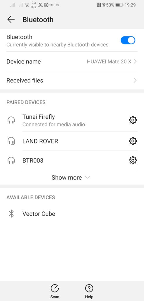
Here you can see the ‘Tunai Firefly’ paired with my Mate 20 X as a media audio device.


In use I have found the Firefly to perform superbly, just like the Justop. My phone pairs with it quickly and automatically every time I get in the car and it looks terrific too.


This slideshow requires JavaScript.


As you can see from the above photos, the Firefly Bluetooth adaptor is definitely a neater, more compact solution. Only time will tell if it proves to avoid damage better than the Justop device though. I also noticed one unexpected improvement over the Justop – the audio is louder! I no longer have to crank the volume up louder than usual which is a nice bonus.

Overall I think the Firefly Bluetooth adaptor is worth the extra money as it looks neater and more professional. It also doesn’t protrude into the back of the car as much and it seems to output audio at a higher volume. The Justop is still a great solution and is hard to beat for the price – it’s also more ‘expendable’ if it does get kicked due to it’s cheaper price.

Whichever option you choose, rest assured that both devices will do the job. I just thought I’d update the article with my new findings in case it proves useful for someone.

Changing a Boogie Board Battery

Boogie Board LCD Slate/Tablet

Boogie Board LCD Slate/Tablet

A couple of years ago I bought a cool looking gadget called a Boogie Board from Firebox. Intention was to attach it to the fridge-freezer and use it as a paperless notepad for shopping lists, reminders and so on. It has performed that job flawlessly until a week ago when it suddenly refused to erase the contents of the screen. To cut a long story short, the battery was flat and without any power the e-ink display (similar to the original Kindle) couldn’t be erased. The device is sold with a NON-REPLACEABLE 3V battery and is supposed to last for 50,000 screen wipes before losing charge. I’ve had the thing for not much longer than 2 years and even if it had been used and wiped every single day that would be less than 800 wipes, a figure massively short of the touted 50K. I’ve probably erased it once or twice a week so probably erased it 250-300 times, tops!!! When you consider that is cost me £30 and they expect me to throw it in the bin and get another one you can imagine I was not too pleased!

So, being a tinkerer and having nothing to lose if things went wrong I decided to open it up and see if there was anything I could do to salvage it. Turns out it is fitted with a normal 3v Lithium CR2032 Button Cell with the only complication being that it is soldered onto the small PCB inside. The good news is these can be purchased off eBay for a few pounds, complete with the solder tags – a much better prospect than throwing a perfectly good product in the bin and spending £30 to replace it! Incidentally, I did try my local Maplins but they don’t stock this type of battery..

I thought I’d share my exploits in case it can help anyone else in a similar situation.


Prising the cover off

Prising the cover off with a screwdriver

First off, you need to remove the thick top strip (the bit that houses the erase button). There are no screws, it appears to just clip into place by means of four studs spaced across the width of the board. I was able to carefully prise this strip off using a very thin precision flat-head screwdriver, just be careful not to push the screwdriver in too far as you may damage the components inside.


Boogie Board with cover removed

Boogie Board with cover removed

Once it is off you will be able to see the old battery in the centre, soldered to the PCB by means of two ‘tags’. You will need to de-solder the old battery to make way for the new one. Be careful though, I was a little ham-fisted and accidentally pulled away some of the solder pad on one side – luckily enough remained to allow me to continue.


Old battery removed

Old battery removed

Here’s the PCB with the old battery removed.


Replacement 3V CR2032 Battery

Replacement 3V CR2032 Battery

Here’s the replacement battery, complete with tags. You need to make sure you observe the polarity of the tags when you solder it back onto the PCB otherwise it may not work.


New battery fitted

New battery fitted

Once the battery is soldered back on, check the erase function now works by depressing the little silver switch to the top left of the battery. You can then replace the cover strip by simply pressing it back into place and you’ll have a fully working Boogie Board once more!


My fixed Boogie Board

My fixed Boogie Board