Introduction
My A500 motherboard is a Revision 6A which means that it is quite a straightforward modification to get a 512K trapdoor expansion to be seen as additional Chip RAM. The 6A comes with the Enhanced Chip Set (ECS) variant of the Agnus chip called ‘Fat Agnus’ which is able to support up to 1MB total Chip RAM. This 1MB Chip RAM Mod will combine the 512k onboard RAM with the 512k Trapdoor RAM to give 1MB total Chip RAM, just like you get in the later A500 Plus models.
Chip RAM is needed for stuff like graphics as it is the only memory that the custom Amiga chips are able to access and 512k goes nowhere! Opening Workbench windows, increasing the screen resolution, adding a wallpaper all gobble up precious Chip RAM. The popularity of WHDLoad as a means to run old Amiga floppy games off a hard drive is also a problem for 512k machines as most of the games require 1MB of Chip RAM to function.
Checking the Amiga board revision
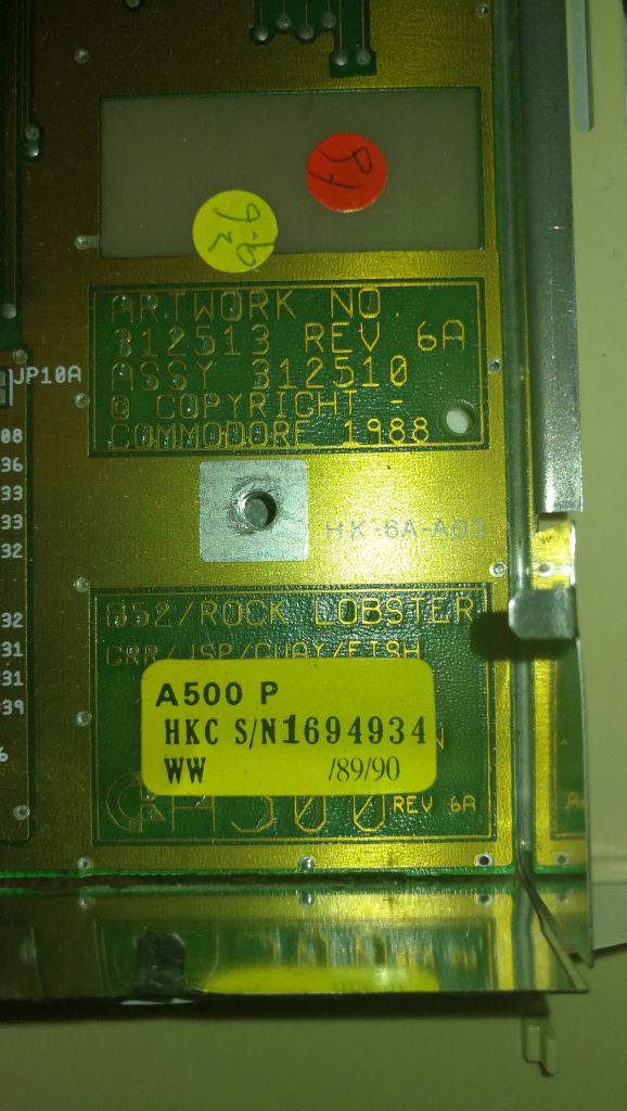
You can check what revision your Amiga is by opening it up and removing the floppy disk drive. The revision number will be etched into a small area underneath along with other interesting information such as the serial number and when it was made. It looks like my board was designed in 1988 (30 years old this year!) but that it might have been assembled in 1989/90 going by the serial number sticker?
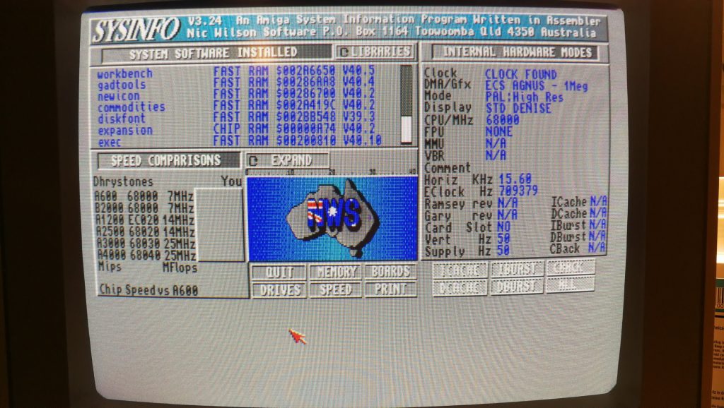
Here’s a screenshot from SysInfo confirming the presence of an ECS Agnus chip – needed for this mod.
Under the knife!
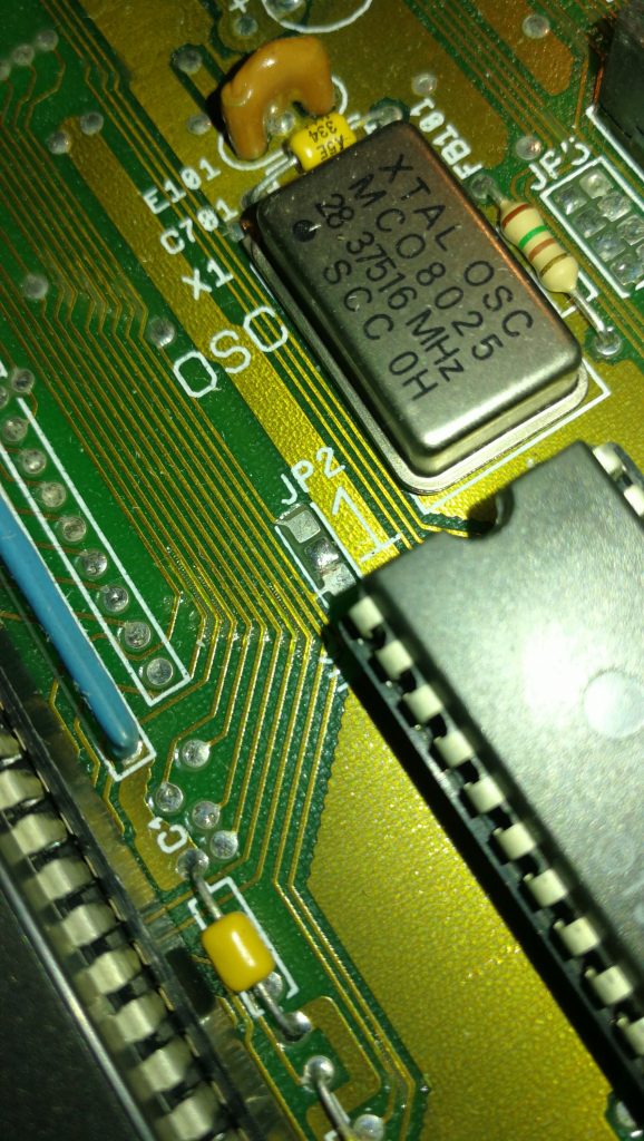
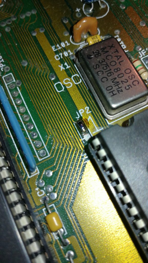
The first thing to do is cut the small trace between the lower two pads (2 & 3). I used a small craft knife but any similarly sharp knife should do the job. Be very careful not to slip with the knife as there are several other tracks on the motherboard that you do not want to damage! To check that you have successfully cut the track you can use a multimeter – there should be no continuity between the two pads if the track has been cut properly.
Bridging the gap
After successfully cutting the track between pads 2 and 3 the next task is to solder the top two pads (1 and 2) together. I found the easiest way to do this was just to keep adding blobs of solder to one of the pads until there was enough to drag across to the other pad and bridge the gap.
The shortcut
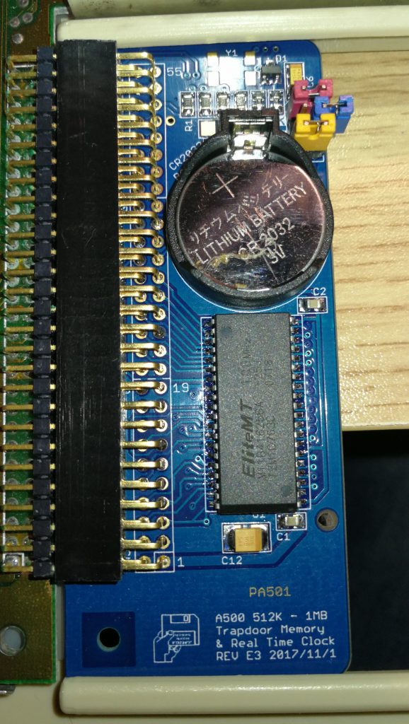
Traditionally the next part of this modification required cutting a track on JP7A but just by chance I stumbled across an advert for a 512K Trapdoor expansion on eBay that bypasses this requirement completely. This particular RAM expansion has a series of jumpers on it that you can use to enable/disable a number of features including using it to expand Chip RAM. It also features a clock with battery backup so it’s a very complete little package. Anyway, in order to have the 512k of RAM added to the pool of Chip memory you need to remove the blue jumper – this basically has the same effect as cutting the track on JP7A.
Testing
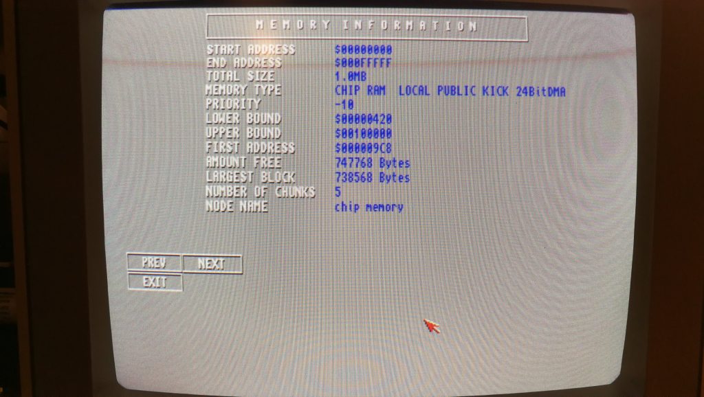
The final step (after putting everything back together of course) is to turn on the Amiga and check that it now has a full 1 megabyte of Chip RAM. Easiest way to check for sure is to load up good old SysInfo and go to the Memory Information screen and you should see 1.0MB Chip RAM displayed. Job done!
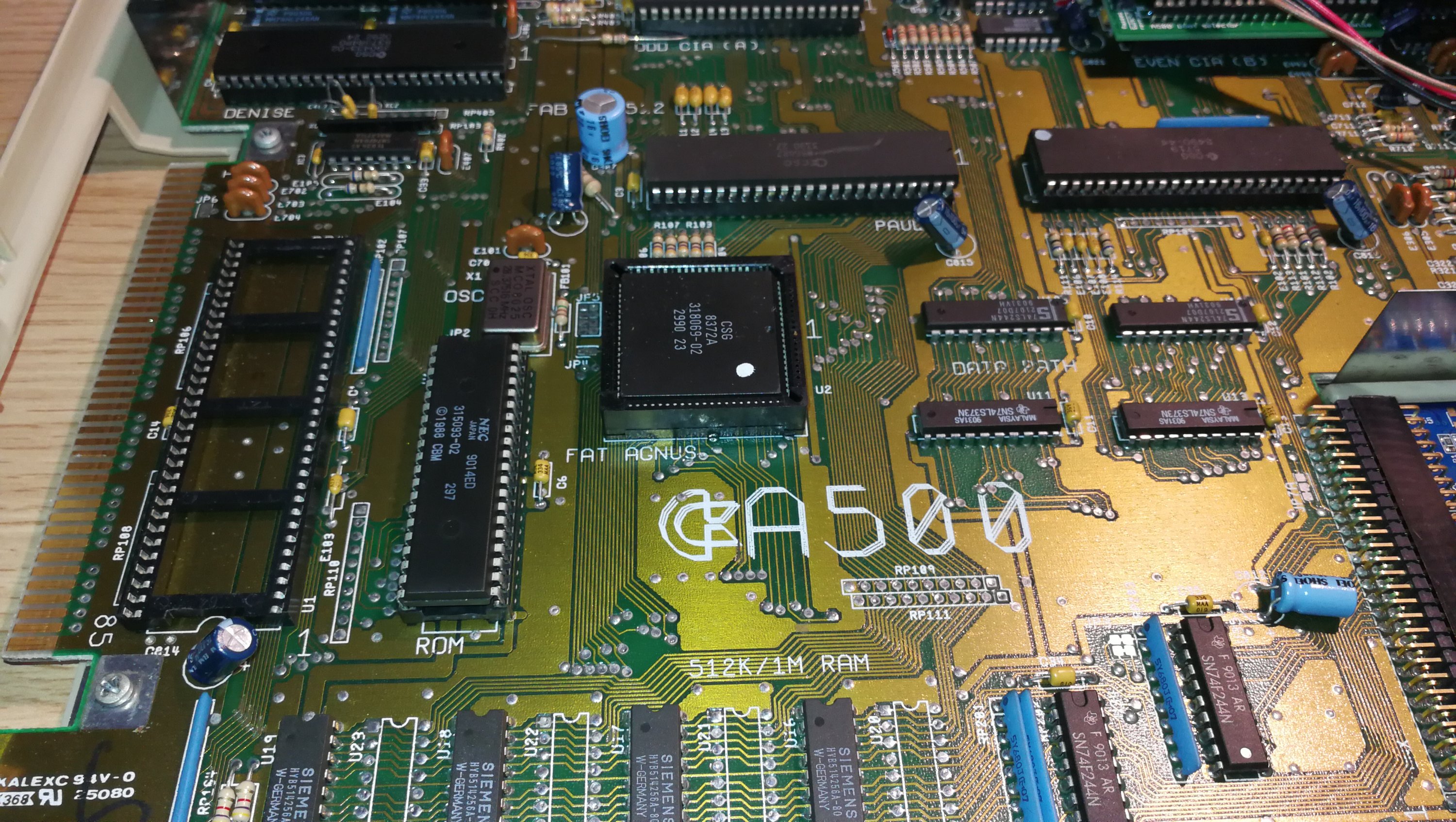

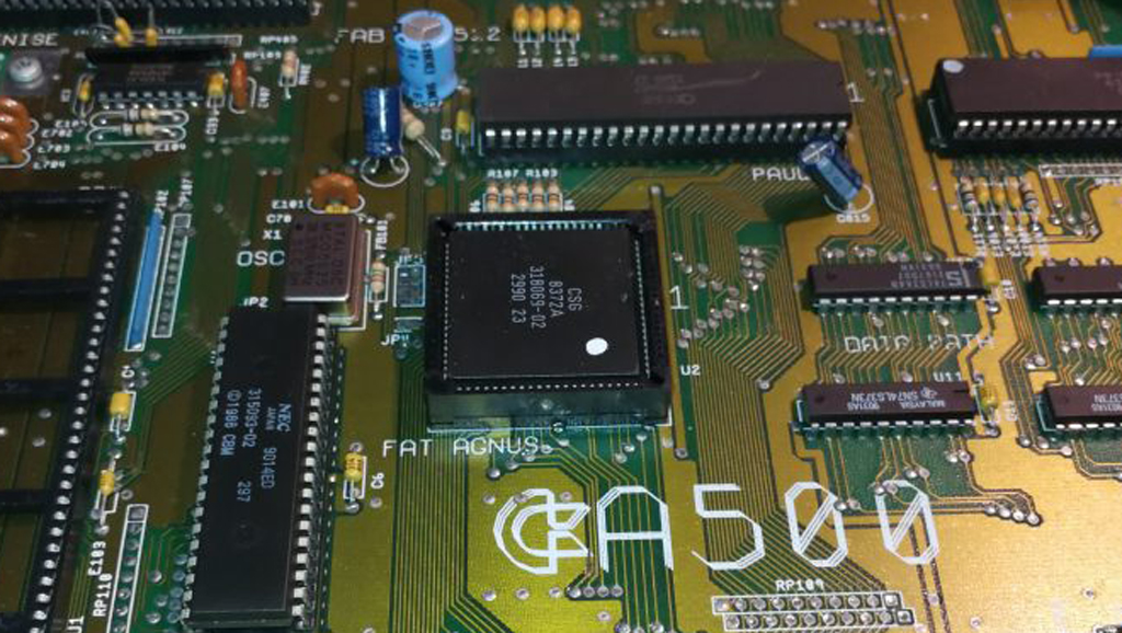
I have been reading that you can change a PAL to NTSC by switching to Fat Agnus chip if so were would I get one and what the real chip number
This isn’t something I’ve ever done myself but I have read about it. You need to make sure your Amiga has at least a Revision 6 motherboard and the Agnus you want is an 8372A which you will probably be able to pick up off eBay. You’ll also need to be capable of doing a spot of soldering to get it working. Here’s a good guide for you: linky
Hi, I have cut between pads 2/3, but don’t have a working multimeter, is there any other way to test if I have made the cut correctly, if I have made the cut properly what would happen after I turn it on etc, is there a way to test that way. Thank you.
Hi,
Sorry I’m afraid I don’t know of any way to test it without a multimeter. You can pick a cheap one up on Amazon for 5 just quid though.
Thank you for your reply, I managed to borrow one and good job as first of all I didn’t cut the trace enough, then didn’t solder enough. Tested continuity and all ok, problem is I can’t now boot. I have the Terriblefire 530, could this be the reason or something else, thank you.
I’ve got no experience of the TF530 in an A500 but it’s possible. It’s also possible you might have inadvertently overshot with the knife and cut through another track. Inspect the area with a magnifying glass and check the tracks are in tact.
When you say it won’t boot do you mean you just get a black (or coloured) screen or that it comes on but won’t boot off a floppy or CF card? Normal troubleshooting stuff would be to remove all expansions and unnecessary devices and see if it works then. Also check every chip is properly seated in its socket. Remove the TF card and put the 68000 back in, remove trapdoor RAM, any extra drives, joysticks etc and just have the A500, power and video connected – you should at least be getting the ‘insert disk’ screen. Good luck!
I am an idiot at times, I had the riser on Gary still with it’s own jumper settings, which was used for the previous Trapdoor ram. Took this off and working brilliantly. Thank you for your help.
No problem, glad you got there in the end. 🙂
So I’m onto step “cut JP7A” jumper pad trace on my rev6A- as my card jumpers are mysterious despite much written on the open design 2mb trapdoor men expansion card on abime .net! It has a jumper Ras 0, ras U2, cas 0 (1st 2 are closed), and I tried combos without luck so have to cut jp7- but I assume cutting the lower 2 pads and *not* soldering the upper 2?
It’s been awhile since 1992 when I did this on my former A500!
Tks
Yeah assuming you can’t find the correct combination of jumpers on your RAM expansion (and you don’t want to buy a new one that is guaranteed to work) then you separate pads 2 and 3 on JP7(A) by cutting the track between them and then you leave it there – don’t solder pads 1 and 2 together.
EDIT: There’s a guide on Aminet if you want some further reassurance. Here: http://aminet.net/package/docs/hard/a500chip.
I have a question.
I’m about to do this modification myself. I have a pal rev5 board with an 8371 upgrading to a 8372a and want it to remain pal, do I have to isolate pin 41 on the Agnus chip to do this.
I have read elsewhere that this is the case with European versions.
Hi Clint,
Yes you are quite right there, it would need isolating to prevent your A500 booting into NTSC mode. Here’s a good video explaining an easy way to do this. How to isolate pin 41.
Hi Steven, thanks for the reply. I’m confident I can resume with this now, cheers.
thank you so much for clear simple instructions. I was able to upgrade to 1MB chip RAM without any issues. As I was on a roll, I also modified my GVP A500 HD drive to use Amiga power supply rather than it’s own external power supply following another blog. Very happy Amiga User today.
No problem, enjoy the extra Chip RAM. 🙂
Hi Steven. Happy new year. I am an avid Amiga enthusiast. I have a few 500 Rev6s, a couple of 500+ and a couple A1200’s. I am familiar with Jp4(NTSC/PAL), but I am slightly confused with your article here. Each of my 500s has the A501 trap door memory (512k). I am able to run 1 meg games like the 1m Zaxxon. I see the Jumpers you are talking about. They are default from the factory. What advantage would I get by doing the mod? The reason this came about was an entry on ebay today. It was a 1meg/512k trap door card for $30. It says: Adds 1MB to an A500+ or 512KB to an A500. The jumper needs to be installed for an A500 and removed for an A500+.
https://www.ebay.com/itm/133919710711?hash=item1f2e3c9df7:g:Pp0AAOSwRkFhfeLQ
So here are my questions for my 500:
1). Is the 500 with a 8372 Agnus limited to a total of 1meg? Any options to increase it?
2). If not, I don’t think this 1 meg expansion card will give me anything more than the 512k A501 already is. What advantage is there doing your mods on JP2 and 7A?
3). On the main 500 6A board are 4 Ram chips and 4 “missing” Ram chips. U23,U22,U21,U20 plus 4 small caps. If I were to add these, would I get an additional 512K. And If I add a trap door memory card, will that buy me anything? I understand that the 500+ has a different Agnus chip.
Just trying to see if I missed anything. Thanks Steve! Pete.
Happy New Year Pete! The 8372 Agnus is indeed limited to 1MB – you’d need an 8375 from an A500+ to access 2MB. The main advantage to this mod is that instead of having 512k of FastRAM and 512k of ChipRAM you get a full 1MB of ChipRAM. This is really useful if you want to run larger or higher colour Workbench screens or WHDLoad which doesn’t play nice unless you give it 1MB of ChipRAM. Finally there is no benefit to be had from installing the missing chips – the 8372 can only address 1MB of RAM in total, whether that be a 50/50 mix of chip/fast or 100% chip. Thus adding a further 512MB wouldn’t increase the available RAM and would probably cause some pretty strange behaviour. Best sticking with the 512k trapdoor expansion. If you want more RAM go for a sidebus RAM expansion – you can have up to 8MB plugged in there.
Good tutorial!
Just to remind people…. If you just want to use the Amiga 500 for games from diskette and you don’t intend to try to use larger/higher-color Workbench screens, and you don’t use WHDLoad, then there’s really no point doing this mod. 1MB games still work fine on 8372A-equipped Amigas with 512K Chip RAM and 512K Fast RAM.
I love this, and this blog too. Very thorough step by step approaches, so needed when dealing with difficult amiga topics, many long forgotten or buried in abime.net posts from a decade + ago.
Thank God you used the newer trapdoor memory card with the jumper feature such that the JP7A jumper 2nd modification wasn’t needed. My 2nd A500 suddenly has 1 Mb chip mem thanks to you, yay!
Glad you found the article useful. Preserving Amiga knowledge was one of the reasons I started this blog in the first place, both for the community and as a personal reference guide I could come back to in the future.
Hi. my A500 is a rev 6a. there were some damaged traces on the board going to the ram holes on u16-u19. would it be possible to use chips in u20-u23 and add the caps to fix this problem? if so, would I have to change any jumpers on the board to address these spots as the main 512k of ram?
I’d try to repair the damaged traces on the board by either using a conductive silver pen, or bridging the damaged sections by soldering some tiny wires across them.
I tried that but, the damage is a bit too extensive, which is why I was asking about the other ram spots.
Ah right that’s unfortunate. Afraid I don’t know the answer to your other question. Maybe try the EAB forum?