Lyonsden Blog

Tag - repair

Razer Basilisk Ultimate Battery Replacement

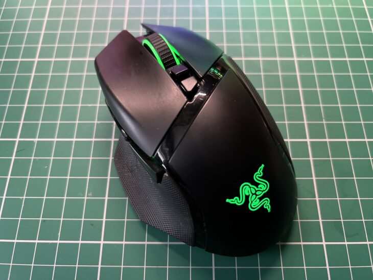
Razer Basilisk Ultimate Mouse

When I am not tinkering around with my old Commodores my ‘daily driver’ computer is a Windows PC and lately the mouse I use with it has been driving me crazy. It’s a wireless Razer Basilisk Ultimate that I bought three years ago and it’s been terrific until recently. Over the past 6 months or so the battery life has deteriorated to the point where it barely lasts an hour before it needs charging again! I made sure the contacts were clean on both the mouse and dock and even charged it with a micro USB cable but nothing worked. Basically the rechargeable battery was completely knackered and so began my mission to replace it!
 

Razer Basilisk Ultimate

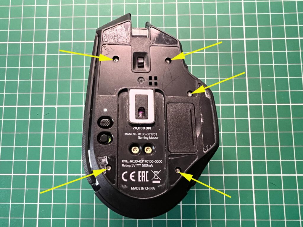
Positions of the 5 screws holding the case together.


The first job was to find where the screws were hiding so I could take the mouse apart. I removed all the glide feet and managed to find two of the screws. The remaining three screws were hidden underneath the serial number/barcode sticker which I also had to remove. The sticker came away quite cleanly with the use of a craft knife to lift up a corner. However the glide pads were really stuck down well so although I got them all off in one piece they were quite tatty afterwards and wouldn’t stick back down properly. They ended up in the bin! The good news if you are looking to do this yourself is that you now know that only the bottom two gliders need removing so if you are careful you might not need to replace them like I did!
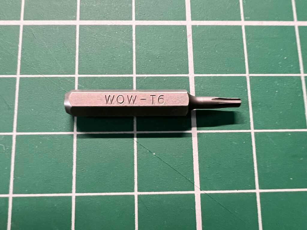
 

The T-6 bit needed to undo the screws.


The screws were tiny little torx head ones and required the use of a T6 bit to remove them as you can see in the photos above and below.
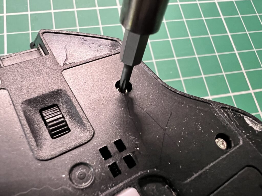
 

Razer Basilisk Ultimate

Removing the screws.


With the five screws now removed the top of the mouse shell could be lifted off. There was a short ribbon cable joining the two halves but it was just long enough to not have to bother disconnecting it whilst working on the lower half.
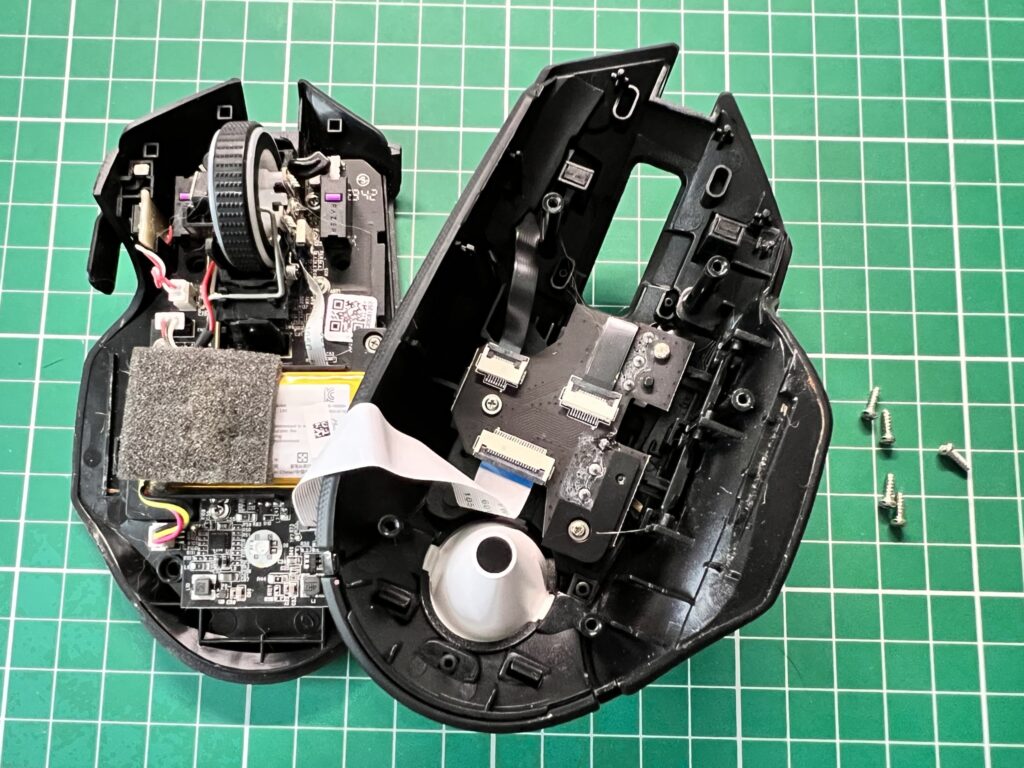
 

Razer Basilisk Ultimate

View of the two halves of the case.


The battery was connected to the mouse by means of a short connector with red, yellow and black wires which unplugged easily.
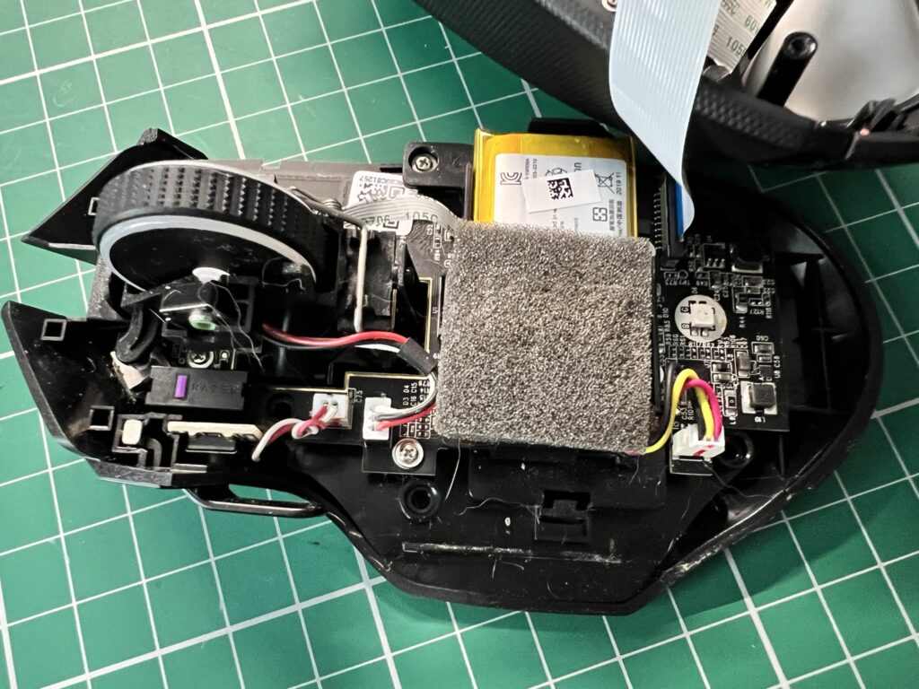
 

Razer Basilisk Ultimate Battery

The battery is lurking under this piece of grey foam.


The battery itself was stuck to the mouse chassis but pulled away fairly easily.
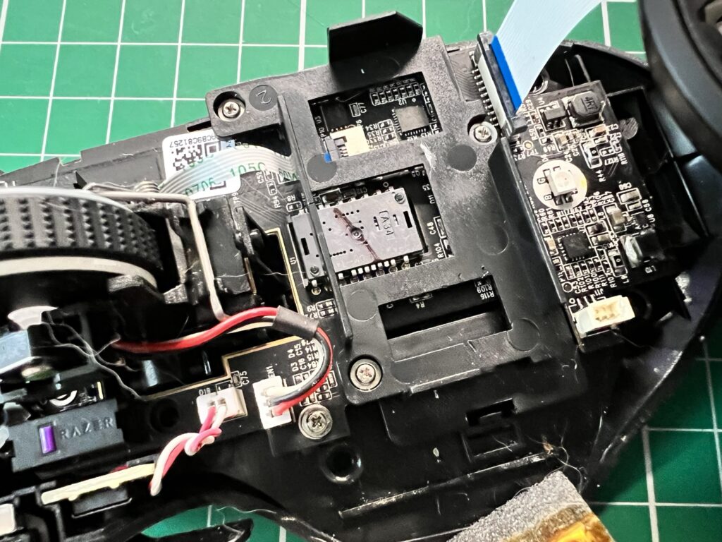
 

Razer Basilisk Ultimate

Battery removed.


The top of the battery had a small square of foam attached. I can only assume it was there to help make sure the battery didn’t work its way loose so I opted to keep it and carefully removed it with my craft knife.
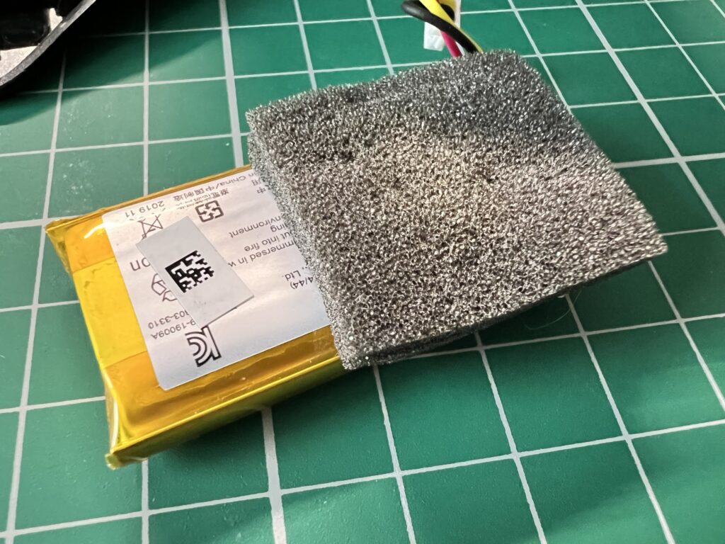
 

Razer Basilisk Ultimate Battery

Razer Basilisk Ultimate Battery still covered by the foam.


With the foam removed (mostly in-tact) I could finally read the label to get the exact specs of the battery.
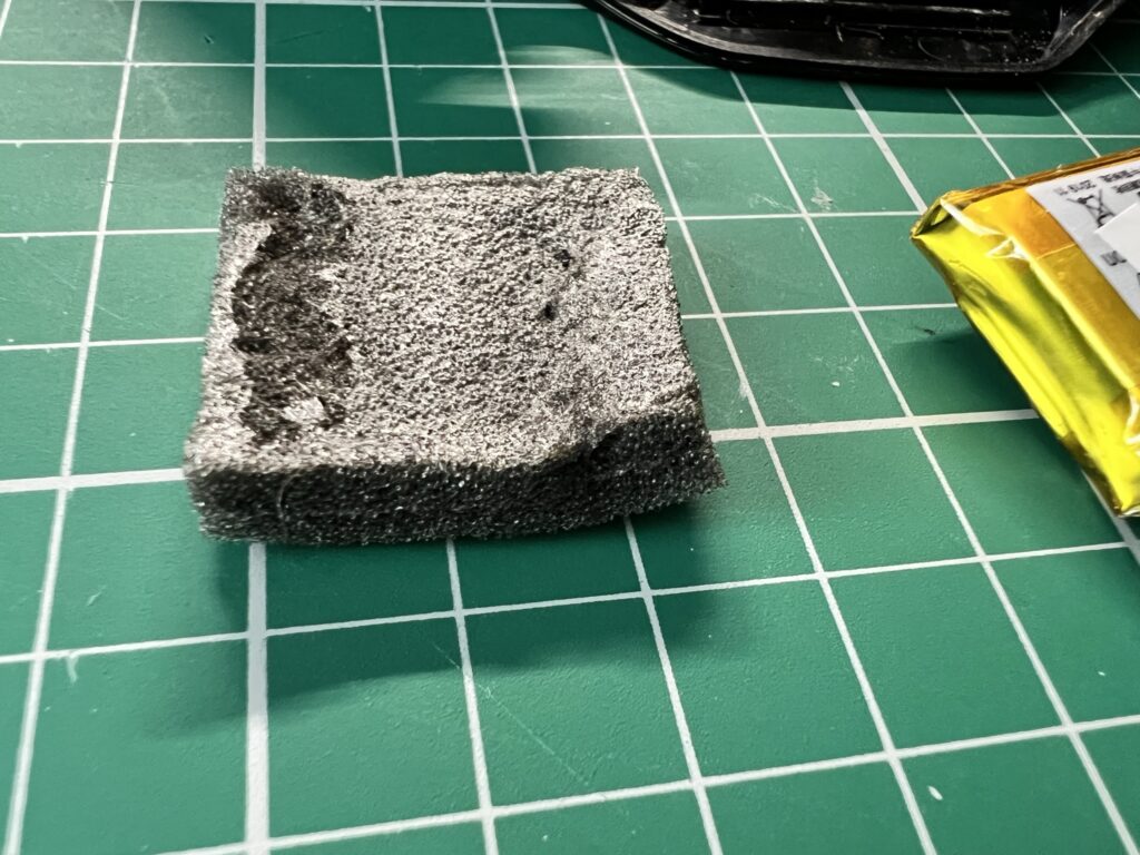
 

Foam removed in one piece.


Sourcing a New Battery

The battery model number was ‘PL782144’ and the specs stated it was 3.7v, 700mAH and 2.59Wh.
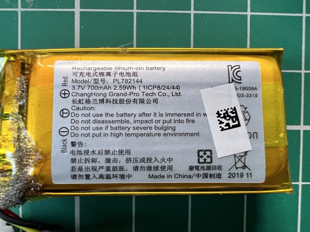
 

Razer Basilisk Ultimate Battery

The old battery label.


These specs didn’t help too much initially as I scoured both Amazon, eBay and even AliExpress for a suitable replacement. I found many batteries with the same ratings but they were all the wrong shape or size or only had two wires instead of three. The battery was quite a snug fit inside the mouse so I needed something the same size.
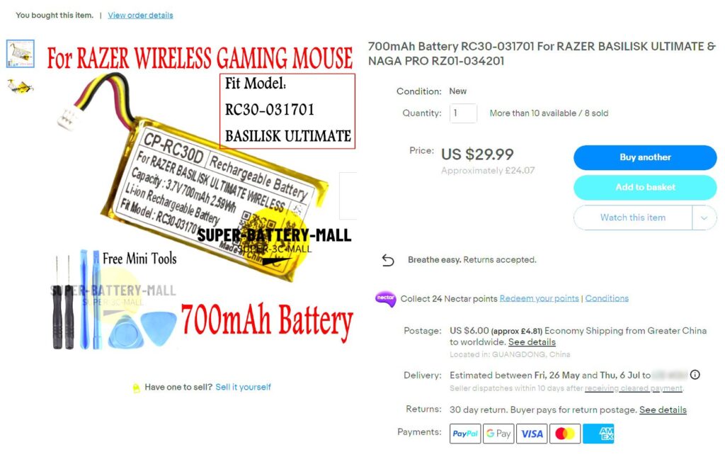
 

Razer Basilisk Ultimate Battery Listing on eBay.


After a lot of searching around I found a battery that claimed it would fit my mouse and had the right specs, connector and size. The seller was based in China and the delivery time suggested it could take up to two months to arrive but it seemed to be my only option so I went ahead and ordered one. Here’s a link to the one I ordered: Mouse Battery. The link works right now but at some point in the future it may not so just use the details in the screengrab above to search around for an alternative.
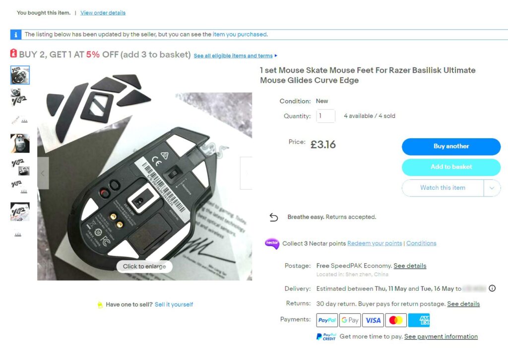
 

Razer Basilisk Ultimate Gliders Listing on eBay.


As I’d also messed up the gliders I found a set of those too here. They were only a few quid including postage from China so well worth it. The picture showed them as being white but they were actually black when I got them. No big deal as I think they look better black anyway. Besides, you never get to see them when the mouse is on your desk anyway!
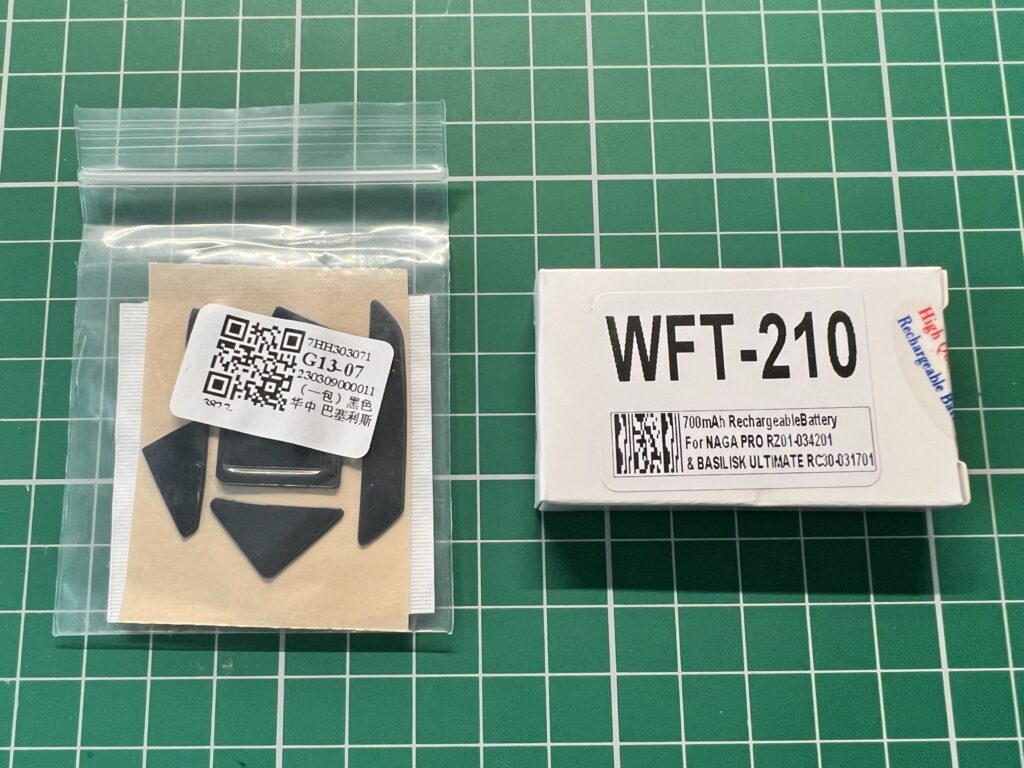
 

New Gliders and Battery in supplied packaging.


Thankfully both items arrived in a little under three weeks, much sooner than the listings had stated. I guess they quote the worst case scenario so that people don’t complain.
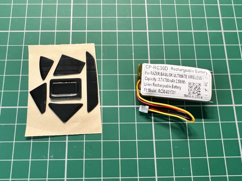
 

New Gliders and Battery unpacked.


When I placed the battery next to the original they were a pretty good match in terms of size with the new one just a millimetre or two smaller.
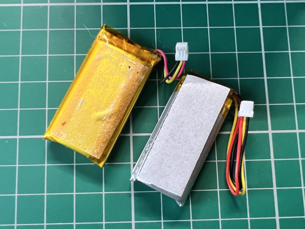
 

New Gliders and Battery in supplied packaging.

Old battery (left) and new battery (right).


Installing the New Battery

Now that I had everything I needed to fix my Razer Basilisk Ultimate mouse I set about finishing the job.


This slideshow requires JavaScript.


The first thing to do was peel off the adhesive cover on the new battery ready for it to be stuck into position.
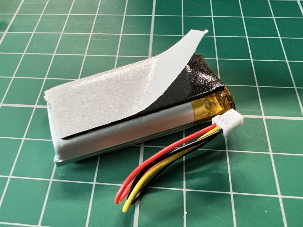
 

Peeling the tape off the adhesive pad.


I made sure to orient the battery with the cable nearest the socket but as it was quite a bit longer than the original I looped it around a section of the battery holder to keep it from getting into harms way when reassembling the mouse.
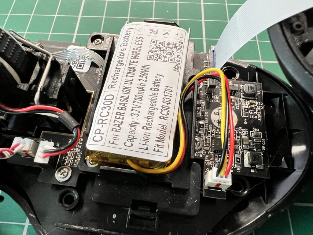
 

Razer Basilisk Ultimate Battery

New battery fitted.


Once the battery was fitted and the wire connector plugged back in I re-fitted the foam pad to the battery. It had enough residual stickiness left to just stick right back on. Not entirely sure it was necessary but it was on there before so I put it back,
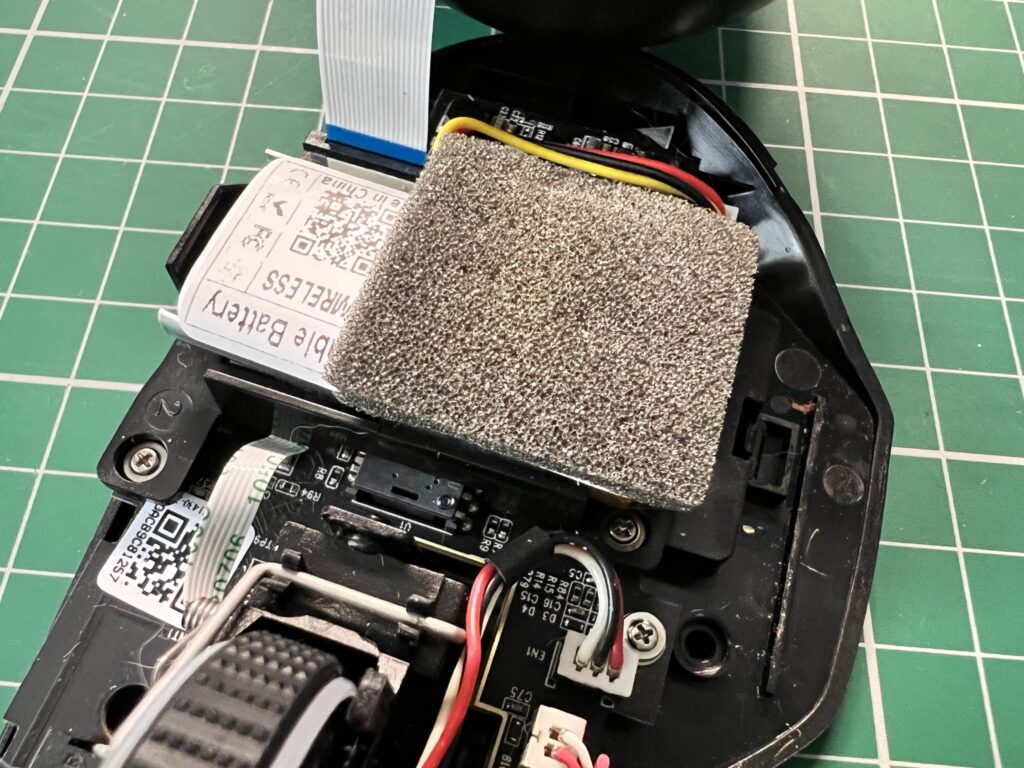
 

Old piece of foam re-fitted.


With the battery stuck in place, reconnected and foam replaced I put the case back together and turned my attention to the bottom of the case…


Fitting the New Gliders

To fit the new gliders I used a pair of precision tweezers to remove them from the backing sheet and position them on the base of the mouse before pressing them firmly into place. It’s far easier to see where they go when your view isn’t obscured by the end of a finger!
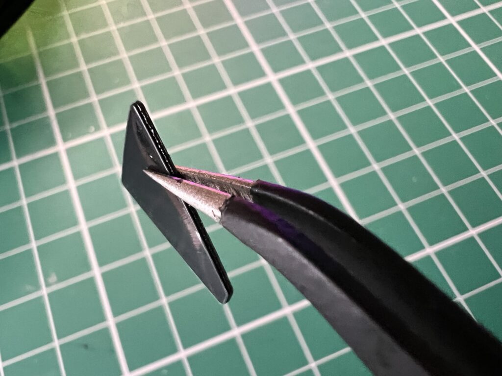
 

Holding one of the gliders with a pair of tweezers.


The gliders had a thin protective film on them that needed removing after application.
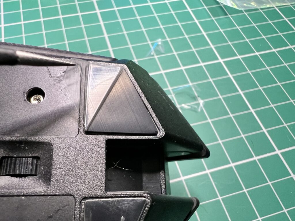
 

Peeling off the protective film.


I also carefully replaced the barcode sticker and also the square glider around the laser in the middle. I hadn’t removed this but since all the new ones were now black and this was still white it had to go!
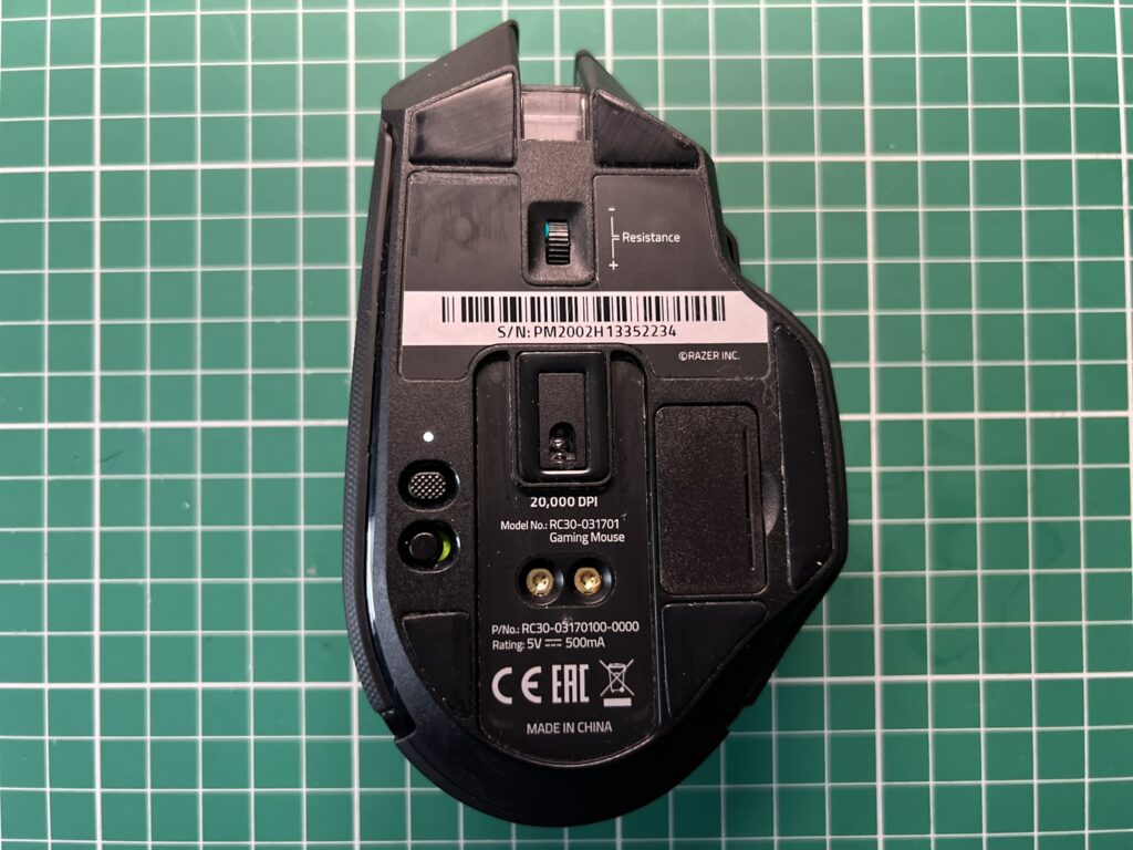
 

Razer Basilisk Ultimate

Ta-da! The finished article with all gliders and serial number sticker fitted.


Whilst I was at it I decided to give the charging contacts a quick clean too.
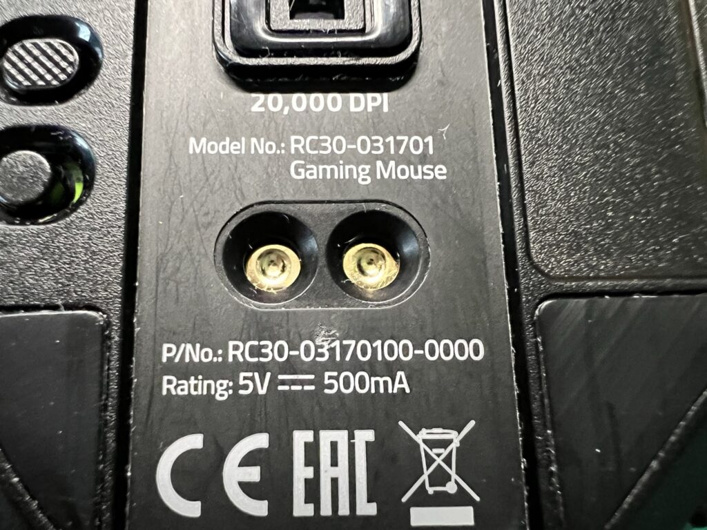
 

Razer Basilisk Ultimate

These are the charging contacts that need periodic cleaning.


A quick spin of an isopropyl alcohol soaked cotton bud was all it took to make sure they were nice and clean. I did the same thing with the prongs of the charging dock too for good measure.
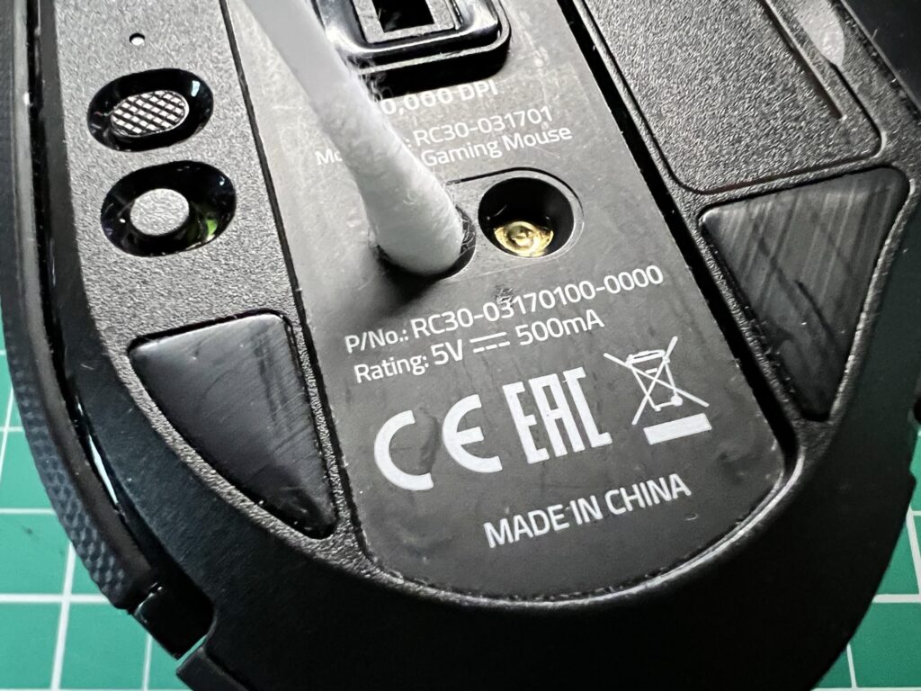
 

Cleaning the contacts with some Isopropyl Alcohol on a cotton bud.


I then gave the whole mouse a quick wipe down to remove any dirty marks I’d made before taking the photo below and then putting it straight back into active service.
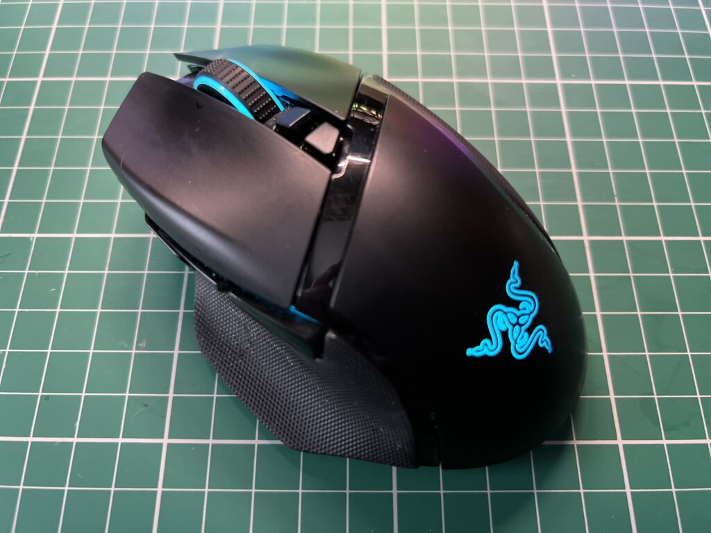
 

Razer Basilisk Ultimate Mouse

My Razer Basilisk Ultimate Mouse – Restored to its Former Glory!


At the time of writing it’s been three days since I fitted the new battery and my mouse is still going strong on the one and only charge I gave it that first day. The battery replacement has been a resounding success and my Razer Basilisk Ultimate is basically as good as new now. The total cost was £32 for the battery, gliders and postage whilst the repair probably took about 30 minutes. Given that the mouse cost me £150 when new I think that was money and time well spent for another three years of top class service (touch wood).
VIC20 Game Box Preservation

It’s winter here in the UK so recently I decided to spend a particularly cold and rainy afternoon on a little VIC20 game box preservation project I’ve been meaning to do for some time.

Why did I want to do this?

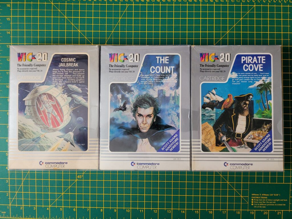
Unfortunately, unlike Sega games which came in sturdy plastic clamshell boxes, Commodore cartridges were supplied in flimsy cardboard boxes. Consequently many of these have not stood the test of time – as a quick glance at all the box-less cartridges on eBay will attest to. I’m really proud that my collection has remained largely in tact for almost 40 years but for them to survive another 40 I figured they’d need a little helping hand.

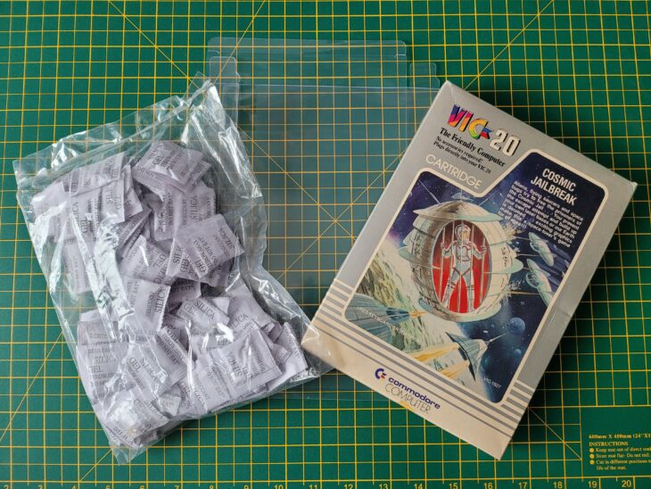
I’d already found some great looking box protectors on eBay and also picked up some sachets of Silica Gel off Amazon for good measure. All I needed was a some time to apply them to my VIC20 cartridge collection.


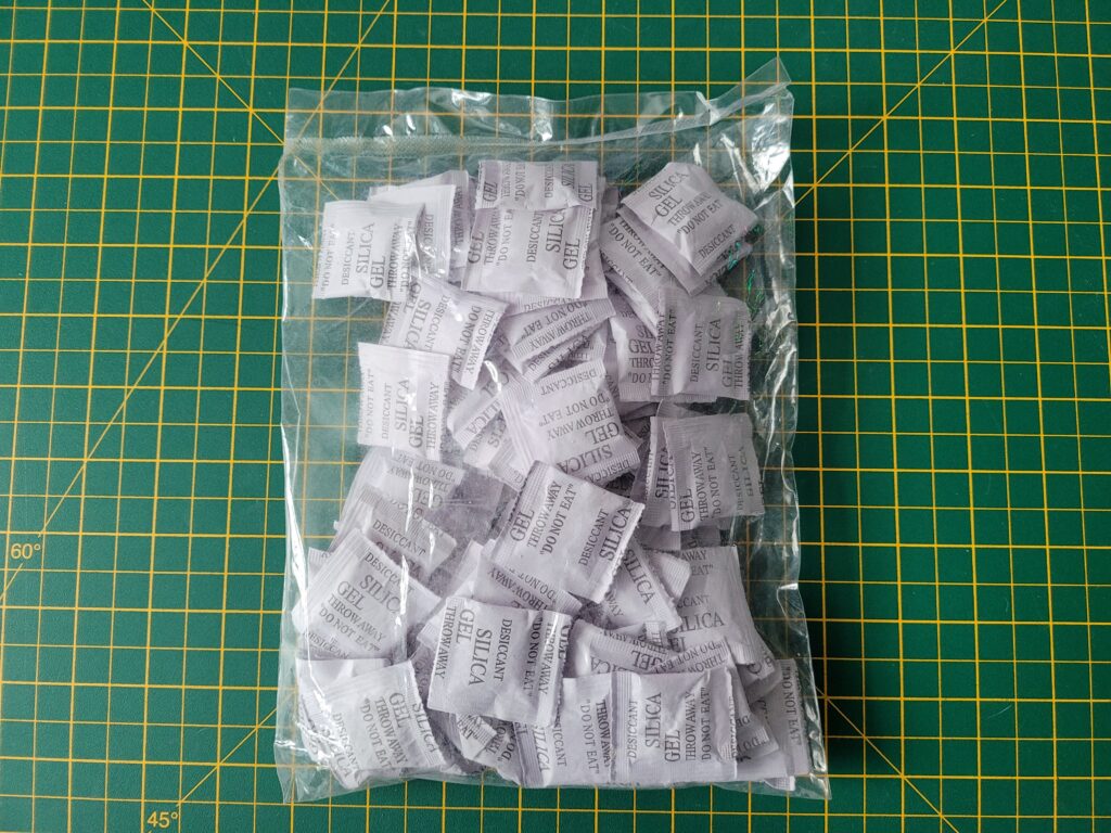
Sachets of Silica Gel

Sachets of Silica Gel


The Silica Gel sachets came in a sealed bag of 100. The moment you open the pack they will start absorbing any moisture in the air so it’s important to minimise their exposure and keep them in a sealed container once opened.


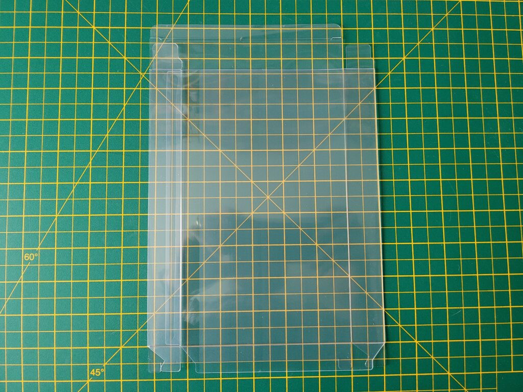
VIC20 Box Protector

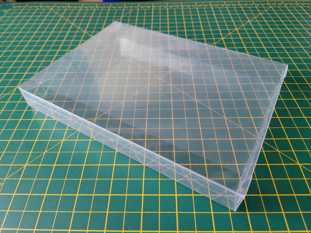
A VIC20 Box Protector folded flat (this is how they are supplied).
 

The Box Protectors

The box protectors are made of PET material which according to Wikipedia “makes a good gas and fair moisture barrier, as well as a good barrier to alcohol (requires additional “barrier” treatment) and solvents. It is strong and impact-resistant”. The boxes were supplied with a protective film on them to prevent scratches in transit. I have to admit I hadn’t realised this at first and was wondering why they looked slightly opaque. When the penny dropped and I removed the film they were crystal clear. You can see the difference clearly in the photos below.


This slideshow requires JavaScript.


Protect and Preserve

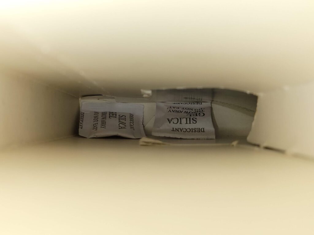
After ensuring that my game boxes were dust free and that the cartridge inside was similarly clean I added a couple of sachets of gel inside each box. The plastic box protectors should do a good job of protecting the contents from the environment but they’re not air-tight so the gel will absorb any moisture that makes its way inside. This should prevent any mould from forming on the contents. At some point in the future the sachets will need replacing but as I’m keeping the games in a nice warm room they should be fine for years.


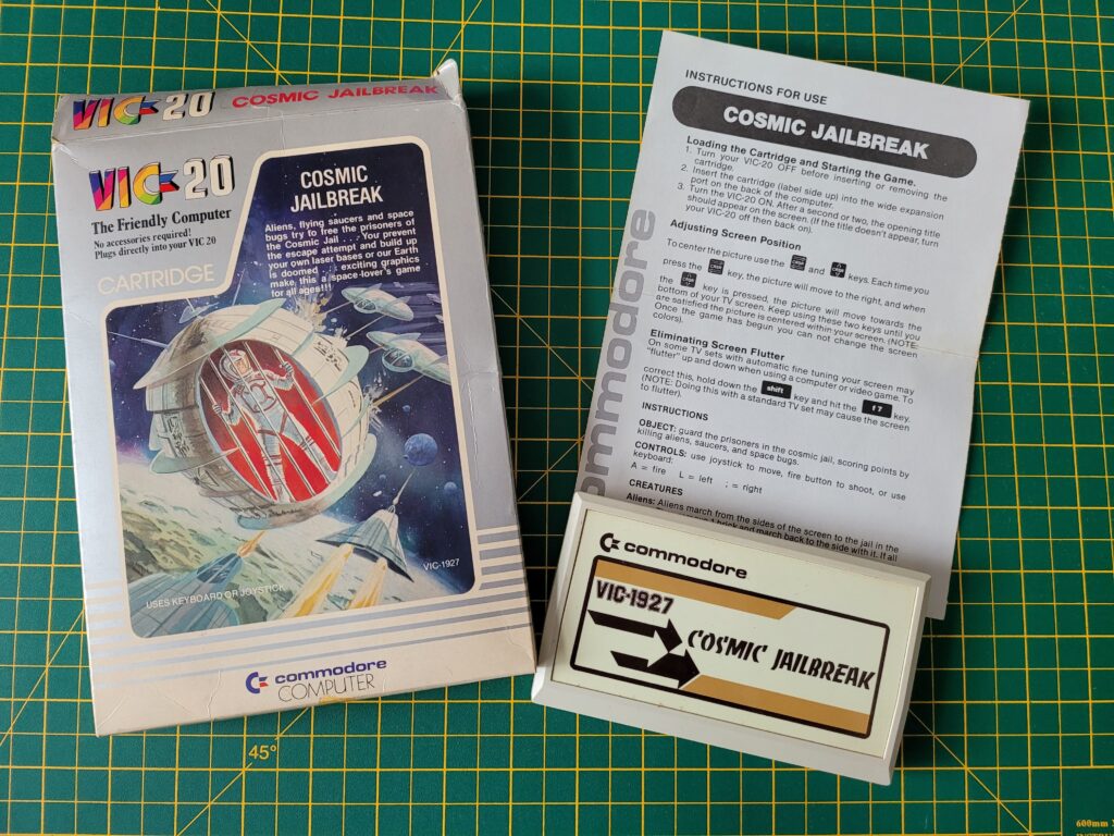
VIC20 Cosmic Jailbreak Cartridge

Game box, with the cartridge and instruction manual laid out alongside it.


If I was placing them in a damp, cold basement, loft or garage then they would need replacing far sooner. However in those locations the games would need to be sealed in an air-tight box too.


VIC20 Game Box Preservation

Silica gel sachets placed inside the bottom of box.


The protective cases were supplied flat-packed so needed folding into shape before they could be used. I found this really easy to do and it took less than a minute per box.


VIC20 Game Box Preservation

A completed box… with the protective film still attached in this photo!


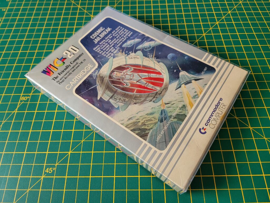
Now it was simply a matter of carefully sliding the game box into the protective case. The cases were a very snug fit so I did need to ensure the box went in straight before it would fit inside.


VIC20 Game Box Preservation

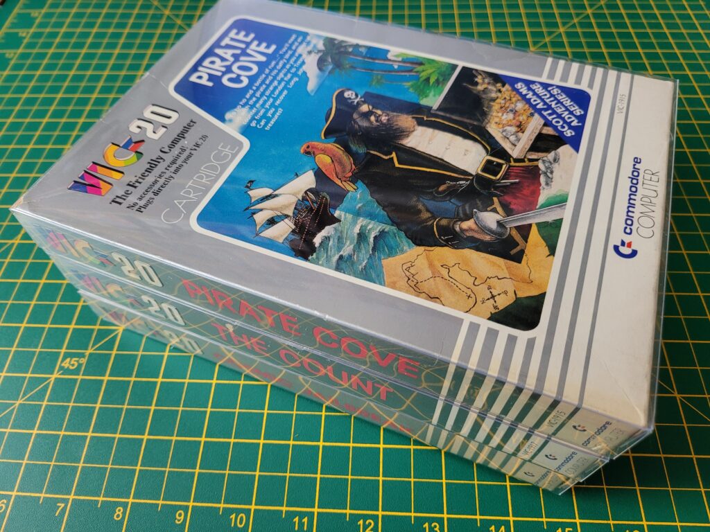
Game box fitted inside a protective case.


There is a seam down one edge (where the box spine is) so I made sure to position that at the back when displaying them on my shelf.


VIC20 Game Box Preservation

Notice how the game on the far left looks slightly opaque – this box still had the protective film on it. It has been removed from the other two.


I think the games look terrific inside the boxes and from most angles you can’t even tell they’re inside a cover.  In fact I’d go as far as saying some of my games looked much better inside the protective cases. Take the Menagerie game shown below which has suffered some box crushing and creasing over the years.


Before…


This slideshow requires JavaScript.


Because the protective covers are such a snug fit they actually force the game boxes back into their original shape when inserted. In effect the covers act as a kind of exoskeleton, almost eliminating the effect of the creasing. The creases are still there of course but just far less noticeable now.


After…


This slideshow requires JavaScript.


All in all I’m really pleased with how this project worked out. It was inexpensive, effective and the whole project only took me a couple of hours to complete. That included taking the photos for this post too.


VIC20 Game Box Preservation

A bunch of VIC20 games in their new protective covers.


My VIC20 games not only look better than before but I feel much happier knowing that I’ve taken steps to ensure they last for another 40 years!


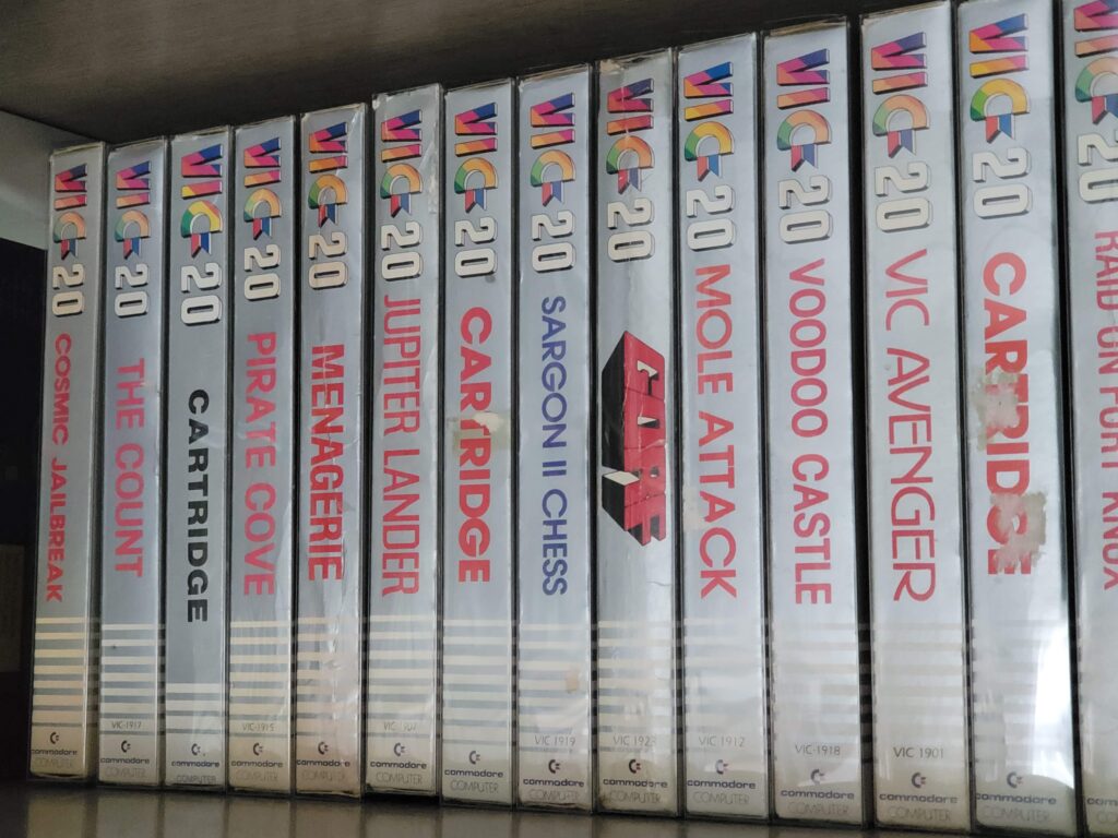
VIC20 Box protectors

Row of protected games on my shelf.

Brucie Bonus

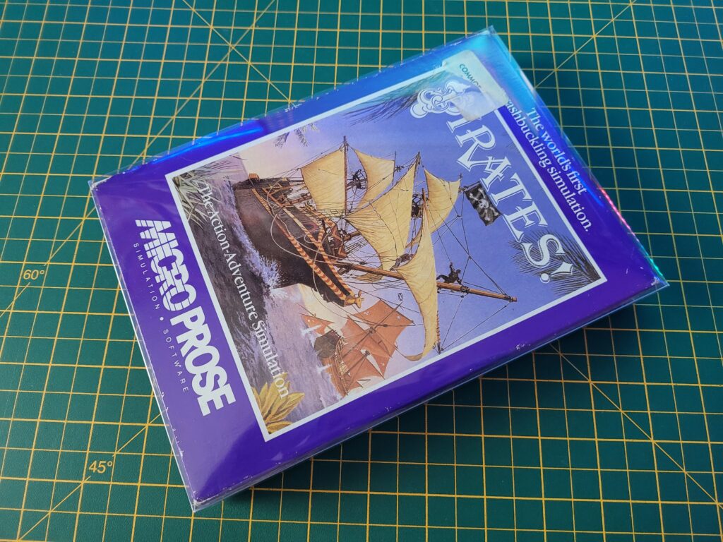
I discovered that the protectors are also a perfect fit for the Commodore 64 Microprose style boxes. This means they’ll also fit similar style boxes from the likes of Rainbird and Level 9. I can see another batch being ordered very soon!


C64 Microprose box protector

The VIC20 box protector also happens to be a perfect fit for the popular Commodore 64 Microprose style game boxes!

Commodore VIC20 ‘breadbin’ Case Repair

VIC20 Case Repair

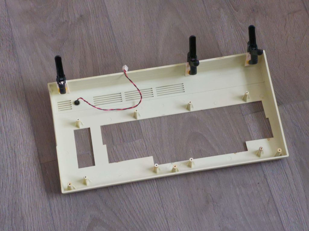
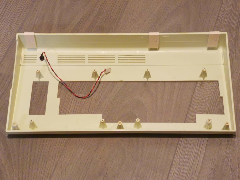
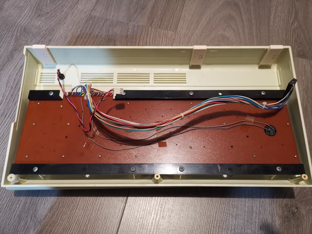
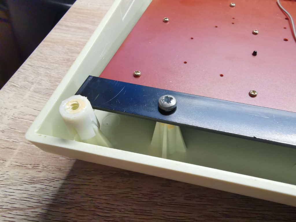
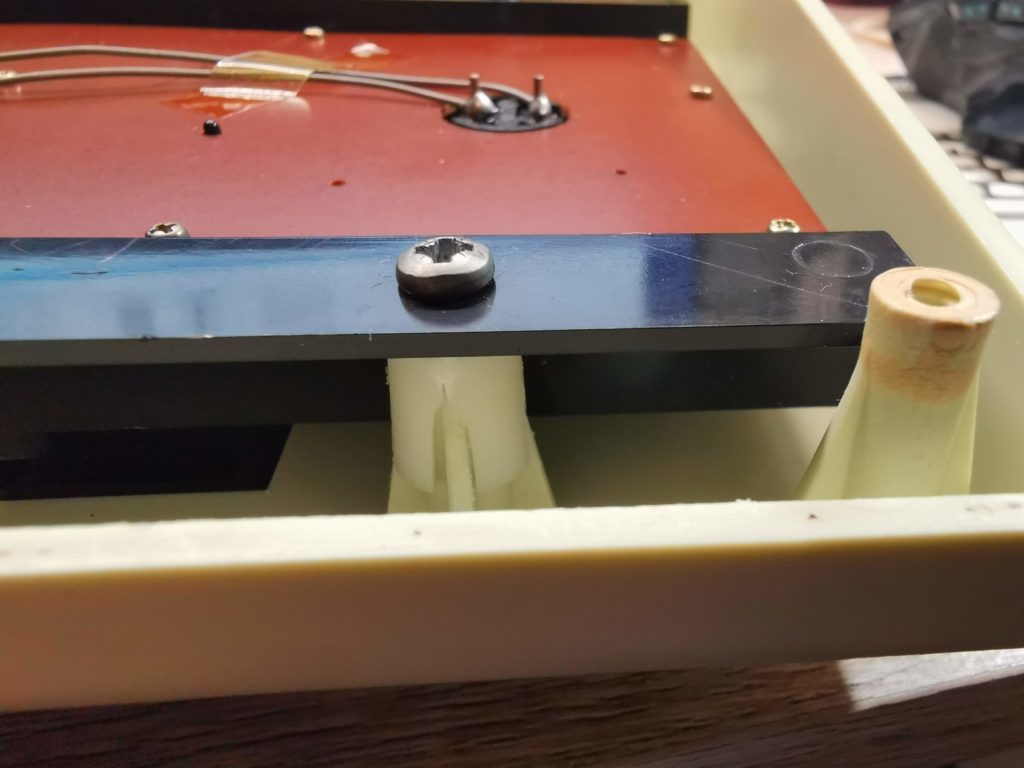
Whilst working on my VIC20 recently I noticed a number of issues with the case. The first thing was that most of the little tabs along the back of the lid had broken off. This meant that the case didn’t close properly along the back at all. The other issue I spotted was that a couple of the plastic screw posts that hold the keyboard in place had split. Not sure why, possibly as a result of over-tightening at some point or the plastic expanding and contracting over the years. It was pretty clear that my dear old Commodore VIC20’s case was in need of some repair and TLC.

By the way, even though this post is all about the VIC20 the contents would be just as valid for a Commodore 64.


This slideshow requires JavaScript.


Naturally I want my VIC20 to remain in as good a condition as possible so I set about looking for a means to remedy these problems. My search concluded when I came across a company in the US called Soigeneris that 3D prints suitable repair parts. The product I ordered from them was the  ‘C64/VIC20 Case Saver Repair Kit‘. The whole thing cost me less than $20 including international shipping (which took about a week). *Note to self – get a 3D printer!
 

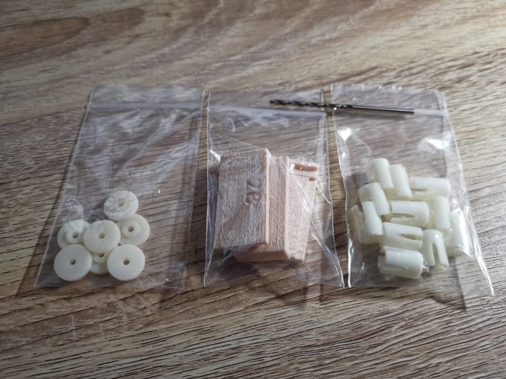
A look at what’s in the repair pack


Inside the pack there are actually 3 different parts to deal with common ‘breadbin’ case issues. New PCB standoffs (not needed here), replacement top case rear tabs and screw post repair sleeves. The drill bit is provided to help centre the PCB standoffs if you are using those.
 

Commodore Case Repair

From left to right: new PCB standoffs (with drill bit), replacement top case rear tabs and screw post repair sleeves.


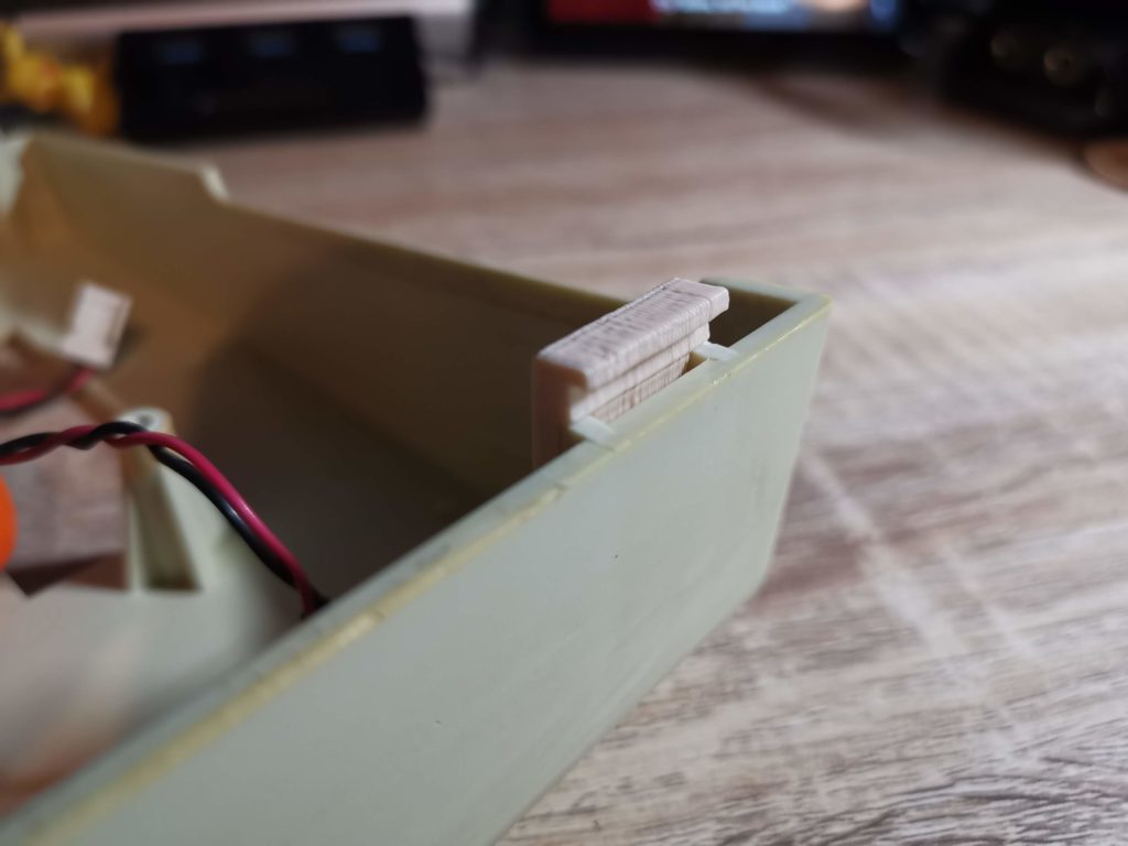
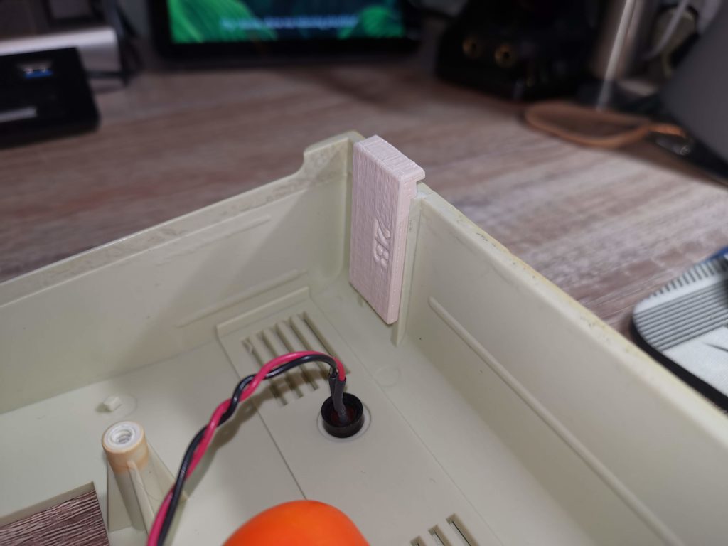
There are several different case styles and they each have different types of hinge tabs. I had to check which variant mine was before ordering otherwise the replacement may not have fit. My particular VIC20 case needed ‘Type 2B’.


This slideshow requires JavaScript.


Fitting the new hinge tabs

I decided to fit the new hing tabs to the back of the upper case lid first. This necessitated completely removing what was left of the existing ones to make way for the replacements.


Commodore Case Repair

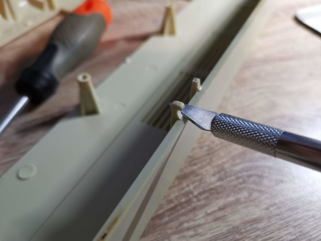
Cutting what’s left of the existing tabs off with a craft knife


This was a simple matter of slicing the tabs off flush with the edge of the case. I used a sharp craft knife for this (and ended up slicing my thumb open) so do be very careful if you are following this post yourself. The plastic was a lot more brittle and softer than I expected so I applied way too much pressure…


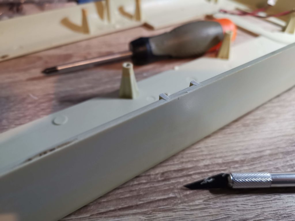
Commodore Case Repair

Tabs completely removed allowing the fitment of the replacement


Before proceeding any further I test fitted the tabs to make sure they fitted flush to the edge of the case. Where needed I shaved some more skin plastic off my with knife.


Commodore Case Repair

Test fitting of replacement tab


The replacement tabs are well constructed and have been designed to align easily within the existing channels.


Test fitting of replacement tab


The instructions recommend using epoxy glue to fix them in in place as it sets rock hard. It also recommends roughening the surface of the case and cleaning it with isopropyl alcohol before gluing to ensure maximum adhesion.


This slideshow requires JavaScript.


I applied a generous amount of epoxy glue and then held the tabs in position using some modelling clamps.


This slideshow requires JavaScript.


Even though my epoxy glue is supposed to be quick drying I set the case aside for 24 hours to fully harden before going any further.


Commodore Case Repair

Holding the new hinge tabs in place whilst glue sets


Preparing the screw posts


Once I was happy that the glue had fully hardened I moved on to tackling the split screw posts. Thankfully only 2 of the posts were damaged but the kit includes enough replacement parts to fix all of them if necessary.


Commodore Case Repair

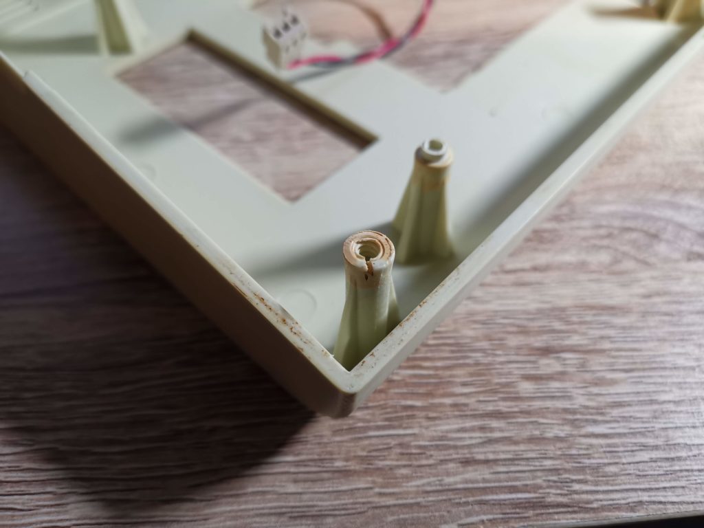
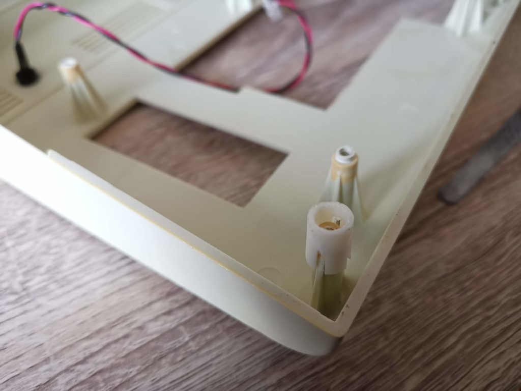
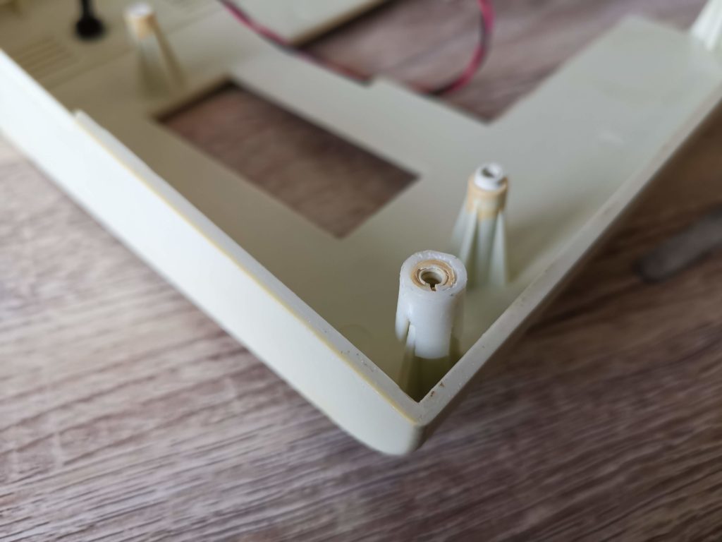
Broken screw post


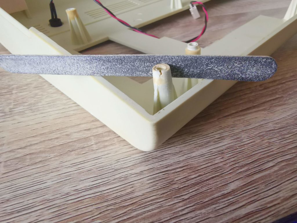
Not only was the screw post split but it had also ‘mushroomed’ out at the top. This meant that it would need to be filed down to it’s original size before the repair sleeve would fit over it.


I used some of my wife’s emery boards to sand the post down. They worked really well too!


I used a few emery boards to sand the posts down to size but a small metal file would have done just as well. It took around 5-10 minutes to get it down to the correct size. I was constantly stopping and checking to see if the sleeve would fit. The last thing I wanted was to sand too much off and have the sleeve become loose.


Commodore Case Repair

Test fitting the sleeve. Note how the castellation allows it to slip over the post buttresses.


Eventually I found the sleeve would slide into place with moderate force so I stopped sanding. Then I just needed to repeat the process on the other broken post before gluing both sleeves permanently into place.


Gluing the repair sleeves


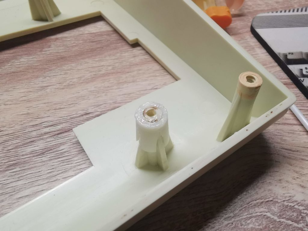
First I cleaned both the post and inside of the sleeve with isopropyl alcohol to make sure no plastic dust was left from the sanding. Then I mixed up a small amount of epoxy glue and applied it to the top of the post before sliding the sleeve down until the two top surfaces were flush.


Commodore Case Repair

Screw post fitted with repair sleeve after sanding it down


I smeared a little extra epoxy on the top of both the posts to fill the splits in the plastic too. There was no need to use any sort of clamp this time as the sleeves were a tight fit. The friction alone was more than sufficient to do the job.


Commodore Case Repair

An extra application of epoxy over the top helped fill any splits or gaps.


Once more the case was then set aside for 24 hours to give the glue ample time to harden.


Repaired commodore case

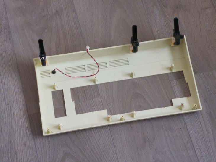
Top part of case with all repairs complete


Reassembly

Now it was time to screw the keyboard back into place and to reunite the top and bottom parts of the case.


VIC20 top case with keyboard fitted

Keyboard fitted back into the repaired top case


I must admit I was a little concerned that the added thickness of the sleeves might have prevented the keyboard from fitting correctly.


Commodore case sleeve repair

Keyboard re-fitted – just enough clearance with repair sleeve


Happily, although a tight fit, the keyboard slotted into place without any extra trimming needed.


Screw post repaired

Screw in repaired post


The screws went into the repaired posts without any issues and were held very securely.


VIC20 with lid hinged open

New hinge tabs seated in their corresponding slots on the bottom case


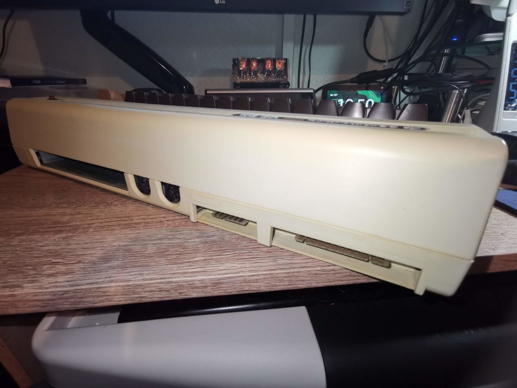
The two halves of the case also fitted back together perfectly. The hinged tabs were very securely held by the epoxy glue and the little tongues aligned perfectly with the grooves on the bottom half of the case. The back of the case was held tightly closed, a vast improvement from how it was before the repair.


VIC20 back of case

Back of VIC20 nicely demonstrating the tightly fitting case halves post repair


This turned out to be a very worthwhile, rewarding and cheap little project. The biggest cost was actually my time, both in preparing the case and making the actual repairs. The whole thing took me three evenings plus a couple of days of glue setting time.

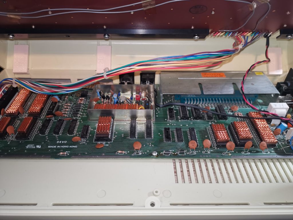
Coupled with my heatsink project and keyboard repair my VIC20 is now in tip top condition again. Hopefully she will be able to take her upcoming 40th birthday in her stride as she marches on up to the big 50.

VIC20 Keyboard Repair

VIC-20

This is just a quick post about how I was able to repair the damaged keyboard on my recently unearthed Commodore VIC20.

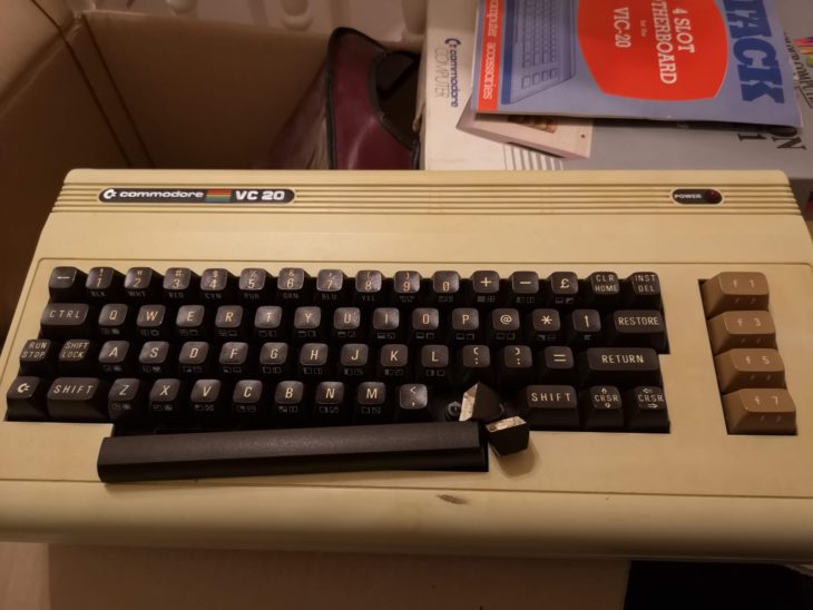
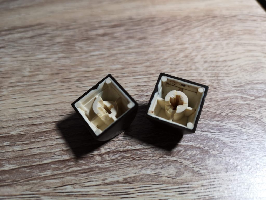
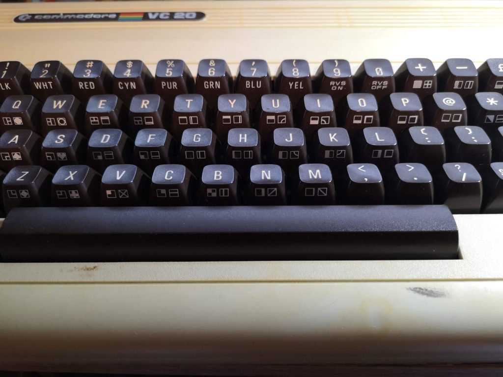
As I mentioned previously in my VIC20 Attic Find post, the decades of storage in my attic had taken its toll on the keyboard. The insides of the keys had become brittle and four of them had broken apart. As you can see from the following photo they were in a pretty bad shape. In this condition they just wobbled around on top of the plungers and fell straight off if the keyboard was turned upside down.


VIC20 Keyboard Repair

Broken and crumbling keys


The quick and easy solution would have been to stick some blue-tack in there but I doubt that would have been an effective bodge for long. Alternatively I could have glued them in place but then they would be permanently attached to the keyboard with no way of removing them for future cleaning or repairs. As my dad always used to say, if a job’s worth doing then it’s worth doing properly!

I did toy with the idea of replacing the whole keyboard with one from a donor machine off eBay. However that wasn’t cost effective and I really wanted to keep my VIC as original as possible.

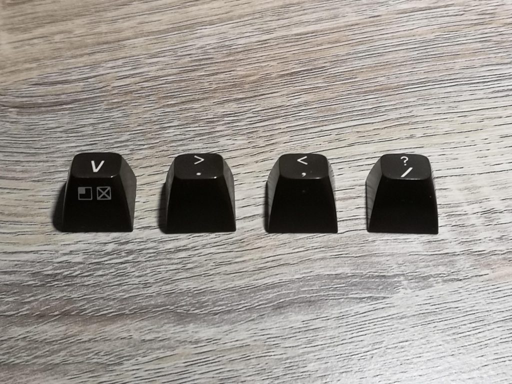
I asked and searched around and eventually stumbled across retroleum.co.uk. They sell (amongst other spares) individual replacement Commodore 64 keys for £1 each. Luckily for me, the keyboard on my VIC20 is identical to the ones found on the original breadbin style C64’s. Not all revisions are so do check carefully before buying C64 keys if you want to fit them on a VIC20.


VIC20 Keyboard Repair

My new VIC20 keys!


Particularly useful was the fact that they sell a wide variety of keys, not just from different models of C64’s, but with different levels of yellowing too! This meant I was able to choose some that would blend in perfectly with the rest of my keyboard. In the end the keys I ordered were described as ‘Breadbin C64 – Keyboard Type 2, Grade 1.5’. A couple of days after ordering them they arrived in a neat little cardboard box.


VIC20 Keyboard Repair

New keys fitted – perfect match!


Fitting the new keys only took a few seconds and I was really pleased to see that they turned out to be a perfect match for my keyboard. My VIC20 is certainly looking a lot happier and I can actually use the keyboard now too.

Now that the keyboard is sorted I still need to look into sorting a few other things out. Next job will be to pop a few heat-sinks onto some of the more critical chips and maybe retrobrite it, if I’m feeling brave that is, (my last attempt was a disaster).

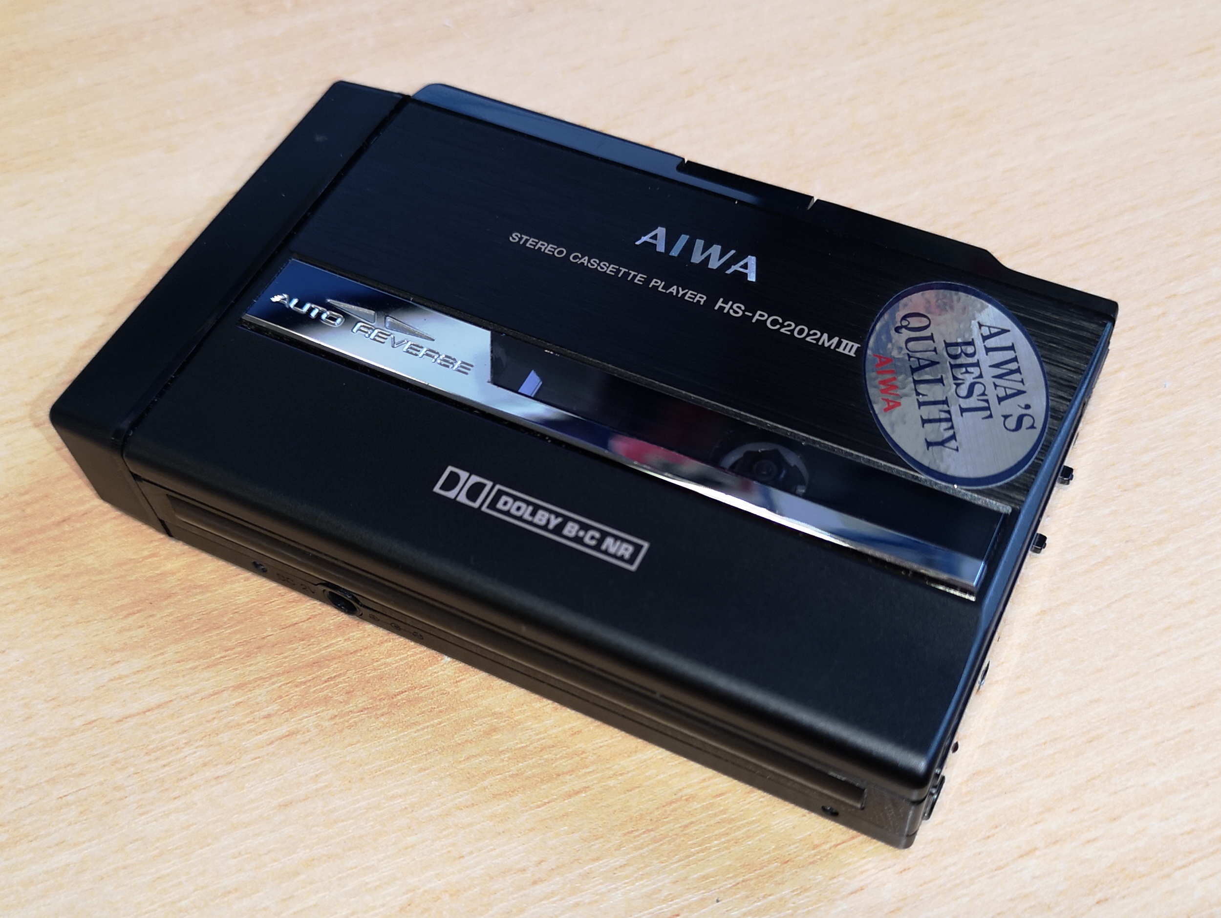
AIWA HS-PC202 Mk3 Cassette Player – Replacing a Drive Belt

AIWA HS-PC202

Introduction

I recently bought a ‘New Old Stock’ AIWA HS-PC202 Mk 3 Personal Stereo off eBay as I just couldn’t resist the idea of unboxing a ‘new’ walkman in 2018. Now I’m fully aware that you can buy brand new ones off Amazon but these are pretty cheap and nasty affairs designed to cash in on nostalgia rather than offer a quality audio experience. This Aiwa model is a quality bit of kit with the ability to play Chrome tapes, Dolby B & C noise reduction, auto-reverse and a super slim, attractive design.

However it had been sat in storage for about 25 years so when I popped in some batteries and tried to play a tape – nothing happened! I could see the power LED light and hear a hiss from the headphones but the spindles didn’t turn. Thankfully I could hear the motor run momentarily if I held the unit to my ear whilst pressing ‘play’. This was a sure sign that the belt had failed in some way which is very common on vintage cassette decks.

This post will provide instructions on how to open up the AIWA HS-PC202 Mk 3 cassette player, and replace the belt. The only tools you need are some small watch-makers screwdrivers and a pair of tweezers. It’s quite a straightforward job as the player has been designed with the foresight that one day someone would need to change that belt!

Getting Started with your AIWA HS-PC202

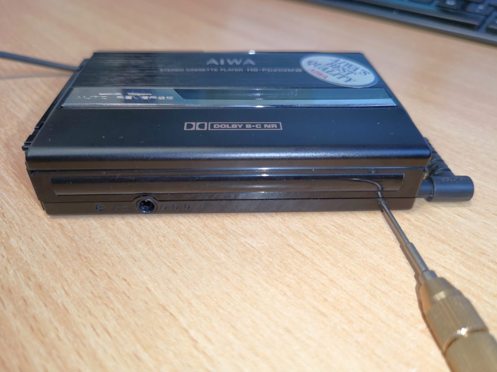
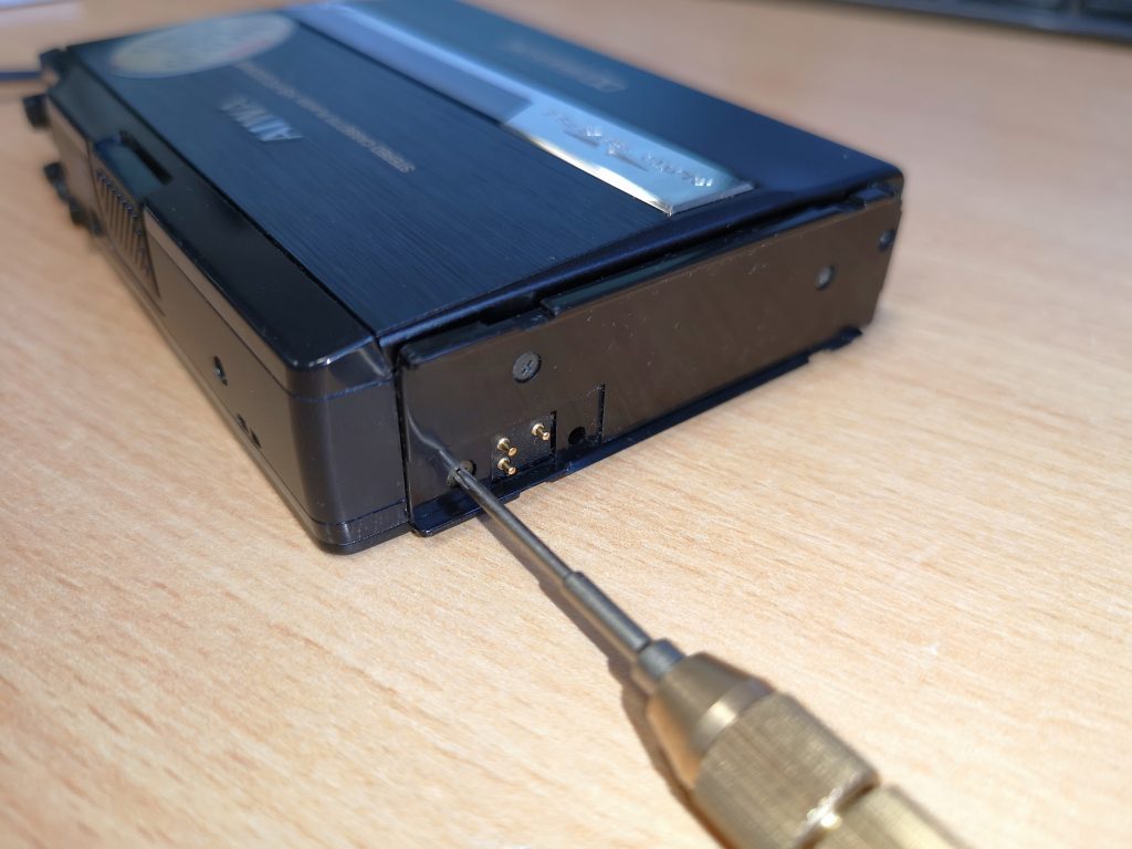
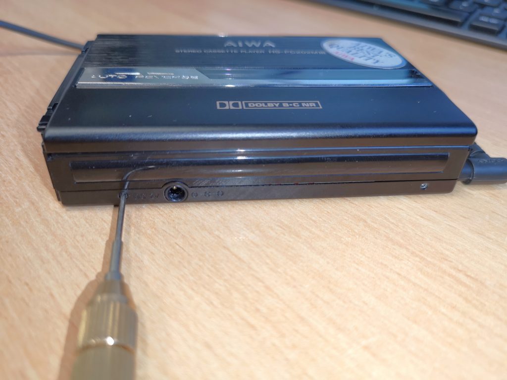
The first thing you need to do with your AIWA HS-PC202 is unclip the battery compartment as one of the screws you need to remove is hiding behind this. Now you need to remove the backplate from the player to expose the belt. It is held in place by 3 tiny screws and a clip that fits inside the case near the play button.

Take your philips screwdriver and remove the first screw shown in the picture below. Place it in safe place, preferably in a small container as the screw is incredibly small and easy to lose. This is a slightly different size to the next two so it should be easy to identify when you are putting things back together.

AIWA HS-PC202

Remove this screw first

Now spin the player around so you are looking at the side where the lid hinges and remove the two screws indicated in the photos below.

AIWA HS-PC202

Remove the left screw

AIWA HS-PC202

Remove the right screw

Removing the Backplate

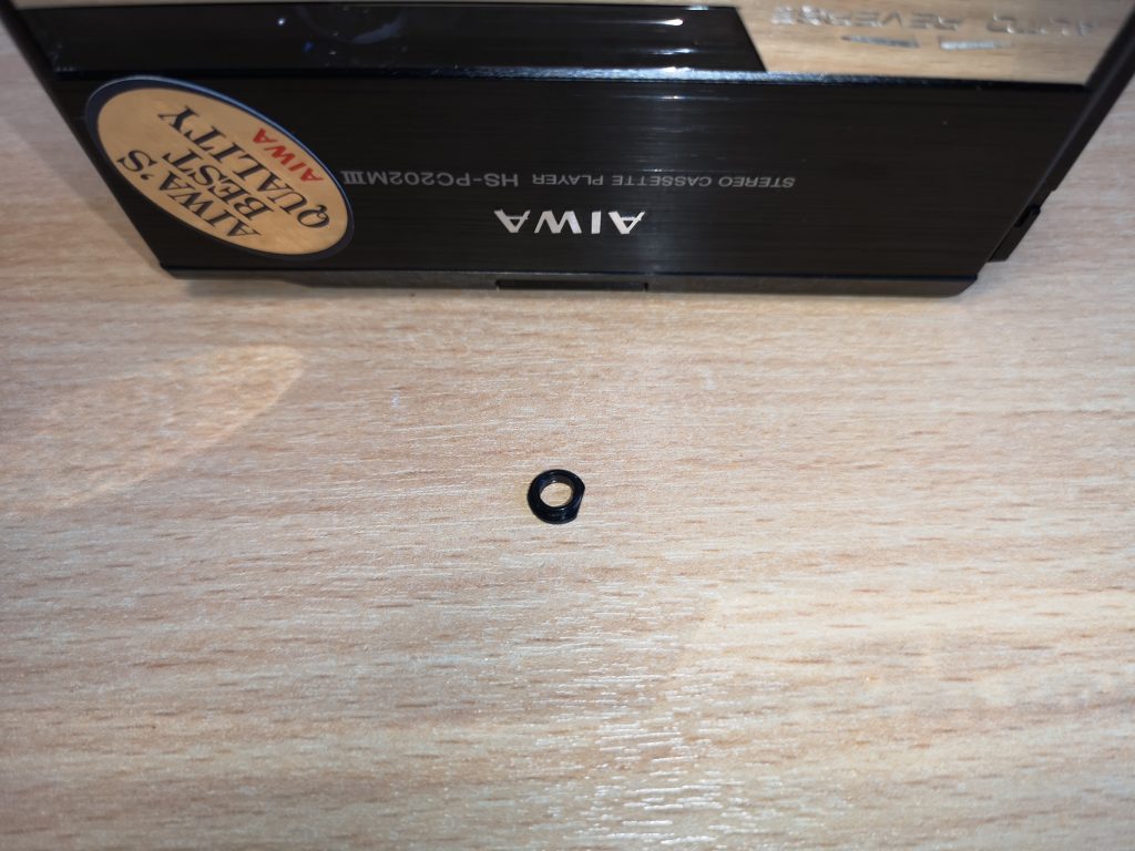
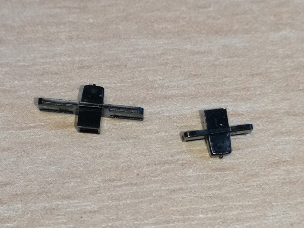
Store these two screws safely with the other and put aside as you are ready to begin removing the backplate now. You need to be careful and not rush this next part as there are a few things that are held in place by the backplate and they will fall out and get lost if you’re not careful. The one thing seems to fall out no matter what you do is a small, circular, black plastic spacer that fits between the backplate and the DC power socket. Now you know about it, be prepared for this and catch it. Store it safely with the other screws.

The other things held in place by the backplate are the Dolby NR and Tape Bias selector slide switches. It’s simple to put them back if they fall out – but if you’re not expecting them to drop out they could easily fall on the floor un-noticed and get lost.

AIWA HS-PC202

This is the small plastic part that will fall out from around the DC power socket.

tiny bits of plastic

These are the Bias and Dolby selector switches that may drop out when you remove the backplate.

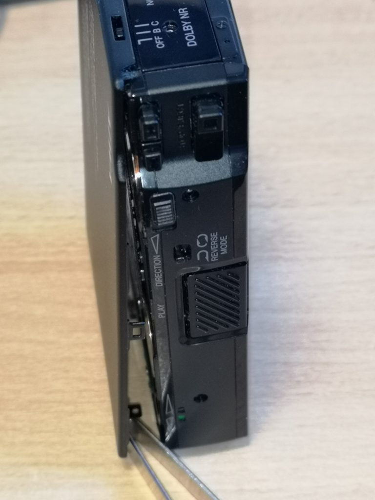
The backplate needs to pivot away from the case from the battery end first. There is a lip at the opposite end by the volume wheel and switches so you need to picture it hinging from that position and focus your efforts on making it open that way. If you place your AIWA HS-PC202  vertically it’s easier to do this and it will prevent the switches from falling out.

AIWA HS-PC202

Gently prise the backplate off, starting at the battery end (the bottom in this photo)

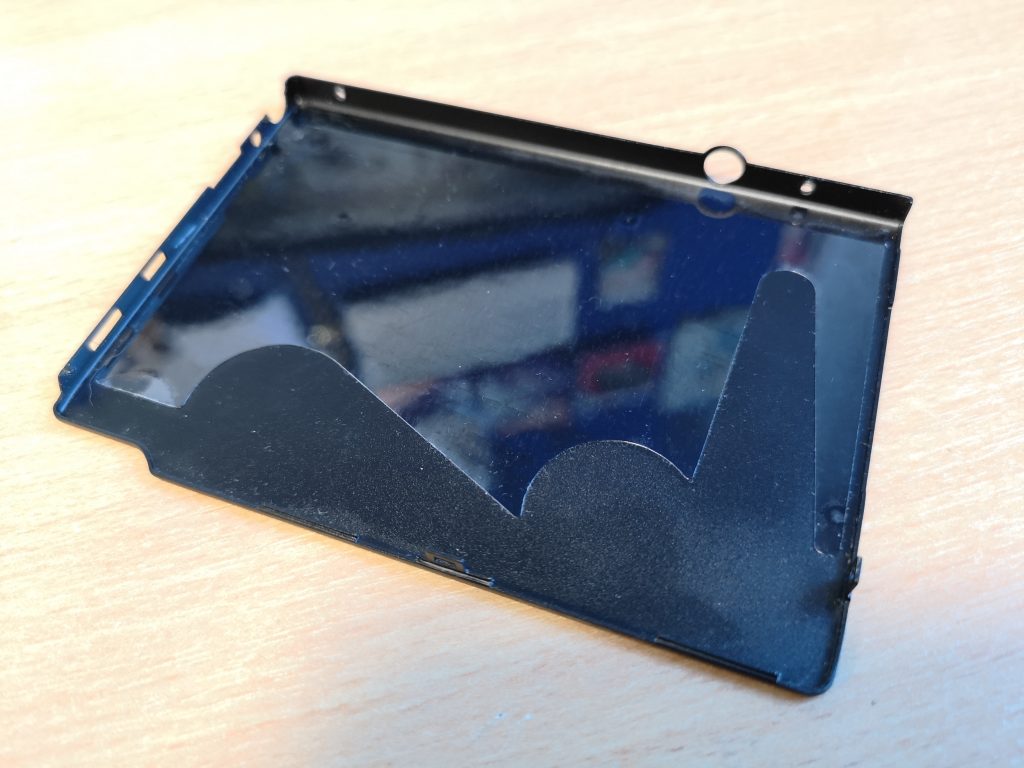
As you can see in the above photo there is a small metal tab on the front edge of the backplate that fits into a plastic lug inside the case, above the play button. You will need to carefully slide a small flat bladed screwdriver in and gently lever the plastic around the play button outward, away from the backplate to release the tab. The backplate should now be free and you can pull it away from the body and slide it upward to remove it, leaving the switches on the top in place.

backplate

The backplate – note screw holes and cut-outs for controls and DC input.

Inside the AIWA HS-PC202 Mk3

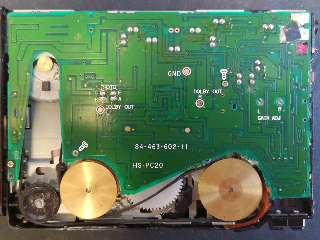
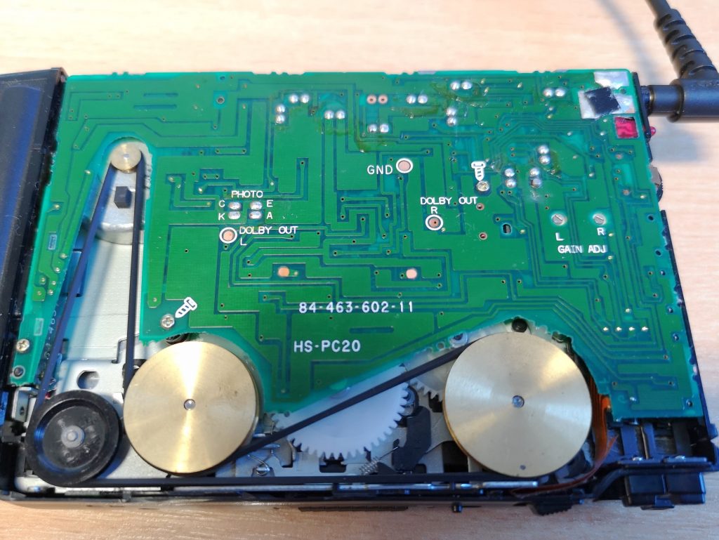
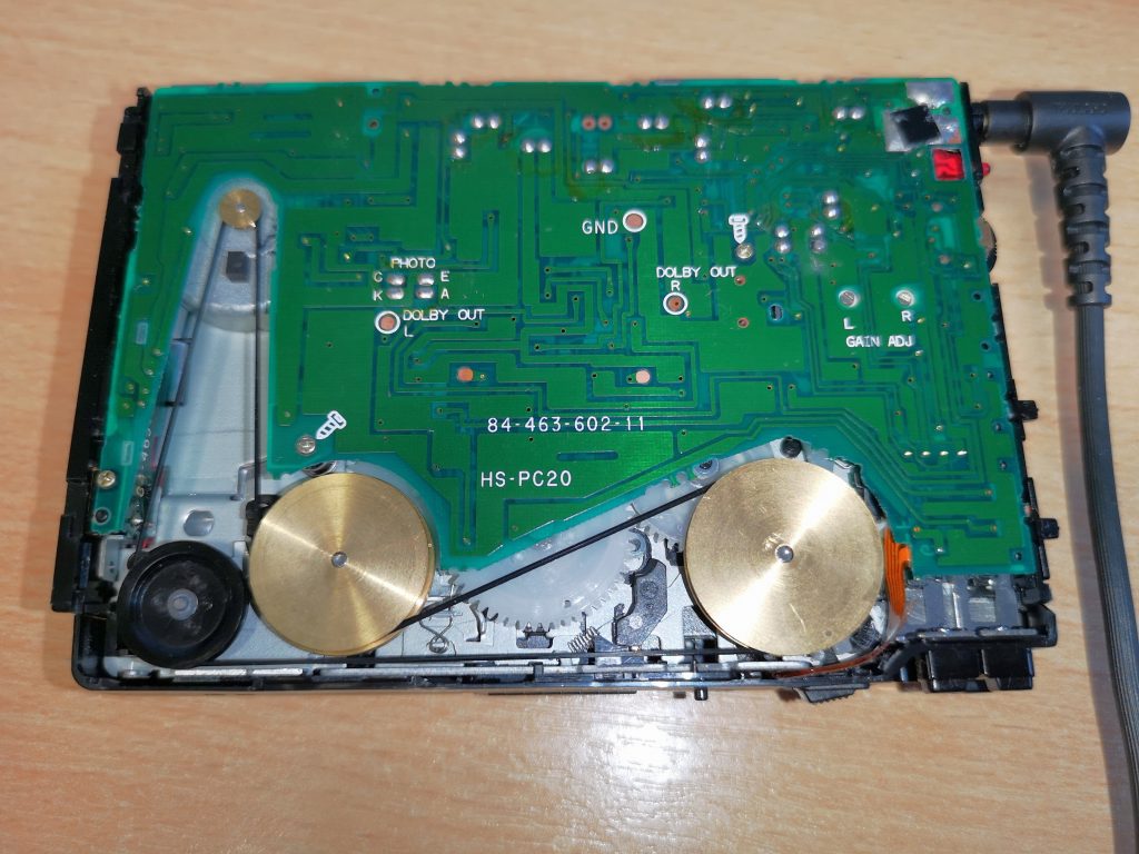
Now that the backplate if off you should see be able to see the circuit board with a cut-out for the belt and pulley wheels just like in the photo below. A belt in good condition should be taught and fit around all the pulleys tightly, something that mine was definitely not doing!

The smallest wheel is the motor pulley, the two large brass wheels drive the capstans and I think the smaller black wheel is there just to guide the belt around the others.

AIWA HS-PC202

Inside the player. See how the rubber belt is no longer taught and is just lying there looking lumpy and uneven

Replacing the Belt (Take 1)

It took quite a lot of investigative work to locate a new belt that was an exact match for the original. Avoid those cheap multi-packs you can pick up off Amazon and eBay from China – the quality of them is variable at best and the chances of getting one that actually fits correctly is next to zero.

The belt fitted to this walkman has a square cross-section, not round or flat like many other belts. It is also very thin – about 0.6mm thick. The length is 76mm. For belts most suppliers use the measurement of the diameter of the belt when laid out flat in a circle. So basically you need to find a 0.6mm x 76mm belt. I couldn’t find one this thin at first so I bought a 1mm x 76mm belt. It did fit and work but was quite a tight fit around the black wheel where it nearly touches the side of the case. It was also only a fraction of a mm away from touching itself (ooerr) where it passes beneath the nearby brass pulley (see the photo below to see how tight it was).

The company I bought the belt from (SignalsUK) was super helpful and based in the UK too. The belt arrived a couple of days after ordering. Although it was thicker than the original it did appear to work OK. (Edit: Sadly this company no longer appear to exist (at least online) so I’ve removed the out of date link to their site).

The belt is very easy to fit. Use your tweezers to place it around the motor spindle and around the other pulleys following the path in the photo below. There is a small plastic tab that protrudes out of the case towards the black plastic wheel. The gap it leaves is very small (you will find it at around the 8 o’clock position) so be careful not to snag or damage the belt here. There will be a a degree of tension in the belt and this is normal so you will need to stretch it a little over the final wheel.

AIWA HS-PC202

The 1mm thick belt – notice how it is practically rubbing against itself where it passes back beneath the left-hand brass pulley wheel.

Replacing the Belt (Take 2)

If a jobs worth doing, it’s worth doing properly – so I continued my search for a better fitting belt. Eventually I stumbled upon a place that custom manufactures belts for a variety of machines, including the AIWA HS-PC202 Mk3. The Mk3 is apparently mechanically identical inside to the Mk2 and so the belt they supply for the Mk2 also fits the Mk3. Here’s a link straight to the correct belt – here. The company, FixYourAudio, is based in Slovakia and is run by a very helpful guy who makes the spare parts purely as a hobby to help enthusiasts keep these old machines alive. A week or so after ordering my belt arrived in the UK so I have no qualms in recommending them. It is ever-so-slightly thinner than the original but is definitely a better fit than the 1mm thick one.

belt path

New 0.5mm belt fitted

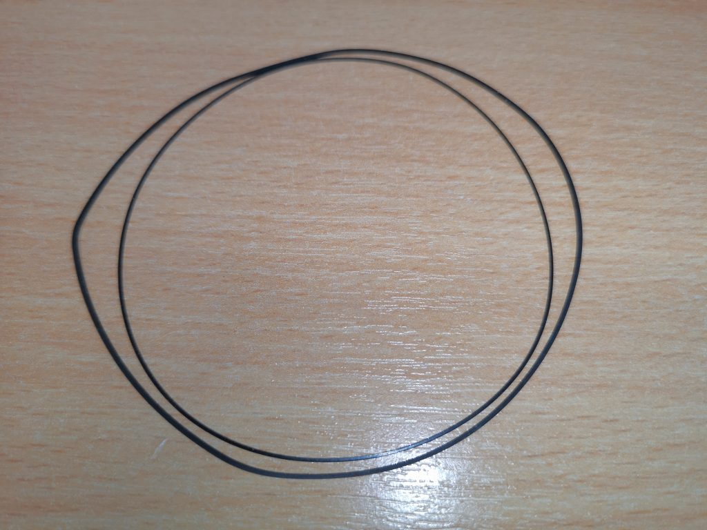
belts

Comparison between the old stretched and worn belt on the outside and the new one on the inside!

Putting it back together

Before you finish off – if you have any additional problems with your player such as unwanted ‘scratchy’ noises when turning the volume wheel or when the headphone jack is twisted in the socket then take advantage of the opportunity and squirt some DeoxIT on them whilst you’ve got the player open. Don’t forget to operate the volume wheel fully a dozen or so times to work the fluid into the pot and clean it up. Likewise for the headphone socket, squirt some in and then insert the plug and twist it around in circles a bunch of times to clean off the contacts.

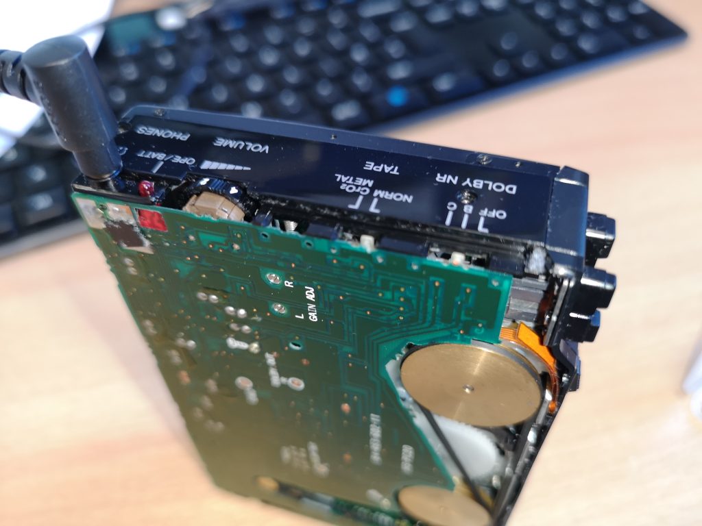
Now you just need to put it all back together. If you knocked off the slider switches then pop them back on now. You will notice that one side of them is hollow and this will sit on top of the appropriate switch sticking out from the circuit board. The larger of the two fits on the Dolby NR slider whilst the other belongs on the Tape Bias switch. Don’t forget to place the little round spacer back over the DC input port. There is a little flat spot on one side of the circle and this should be positioned facing the outside of the case so that it fits flush against the flat edge of the backplate.

back off

View of the controls – note the small white Bias and Dolby switches. It is on these that the black ‘cross’ pieces will sit on if they have fallen off

You may need to press and squeeze gently in a few places, particularly around the play button to get the tab to engage in the lug correctly. However you should not have to force anything. If you feel any resistance stop and check, reposition the backplate, check the spacer and/or the position of the slide switches and try again. Once it has popped back into place and you are happy with the fit all around, replace the 3 screws and you should be good to go! Enjoy the new lease of life your personal stereo has been given!

AIWA HS-PC202

The small plastic spacer fits here. Flat edge towards the backplate.

If you found this guide to replacing the belt in an AIWA HS-PC202 useful then please leave a comment below, it would mean a lot to me. Likewise if you have any questions I’ll do my best to help.

If you’d like to know how to go about de-magnetising the play head in your AIWA HS-PC202 then take a look at this post.

Repairing a Roctec Floppy Drive for an Amiga

Repairing a Roctec floppy drive

This is a guide to repairing a Roctec floppy drive for an Amiga 500 computer.  I thought I’d write this up as much for my own benefit as other peoples so I can refer back to it in another 20 years! LOL.

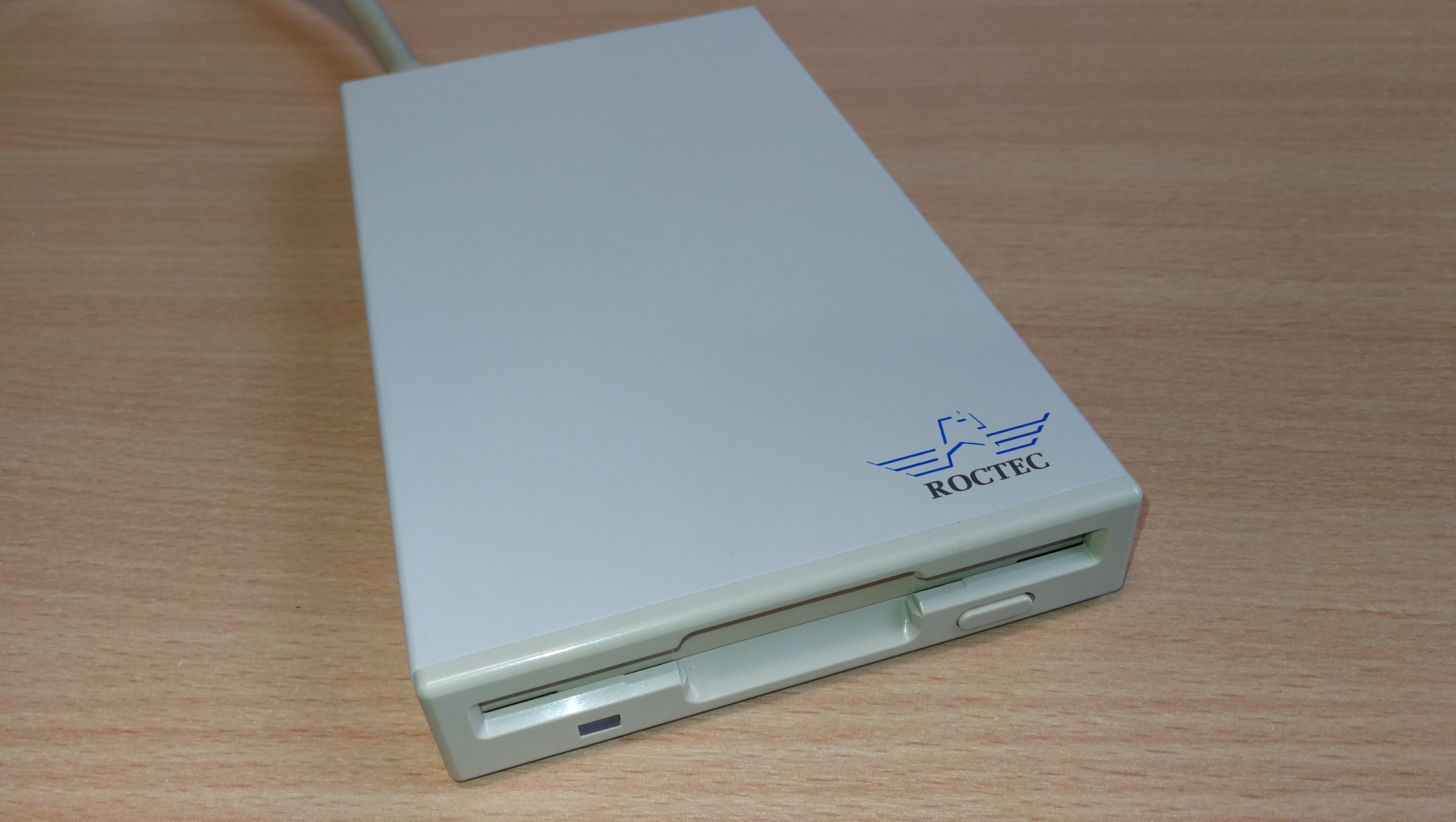
Roctec Amiga external floppy drive

Roctec Amiga external floppy drive

If you ever pop a disk in your external Roctec drive and hear a strange whirring noise and can’t read any of your disks then the chances are you are suffering from a perished or broken drive belt.

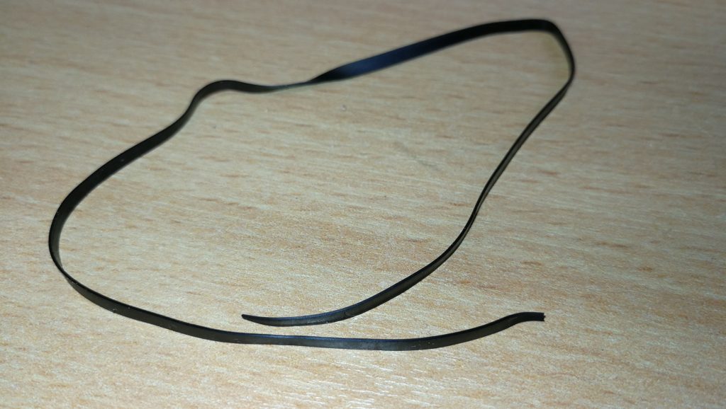
Perished Drive Belt

Perished Drive Belt

These drives use a rubber belt to connect the drive motor to the spindle hub. The rubber belt only has a finite life and given most of these drives are getting on for 30 years old now it’s hardly surprising that they expire.

cof

No tension in old perished belt

The good news is that it’s pretty easy to replace them and I’ll give an overview of what you need to do here.

Getting Started on the Repair

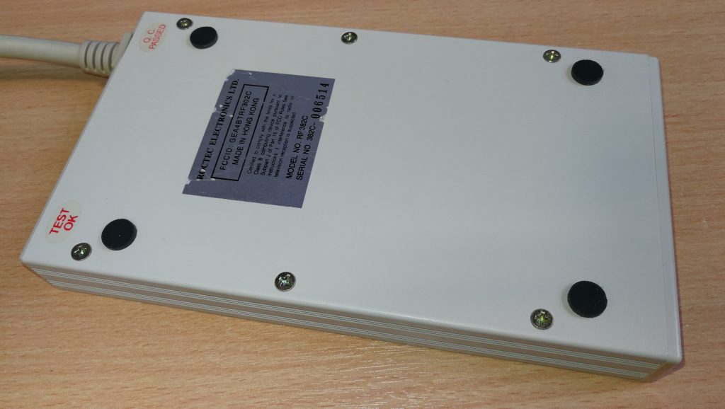
The first thing you need to do is undo the 6 screws on the underside of the drive case using a small philips screwdriver.

Underside of drive case

Remove these 6 phillips screws.

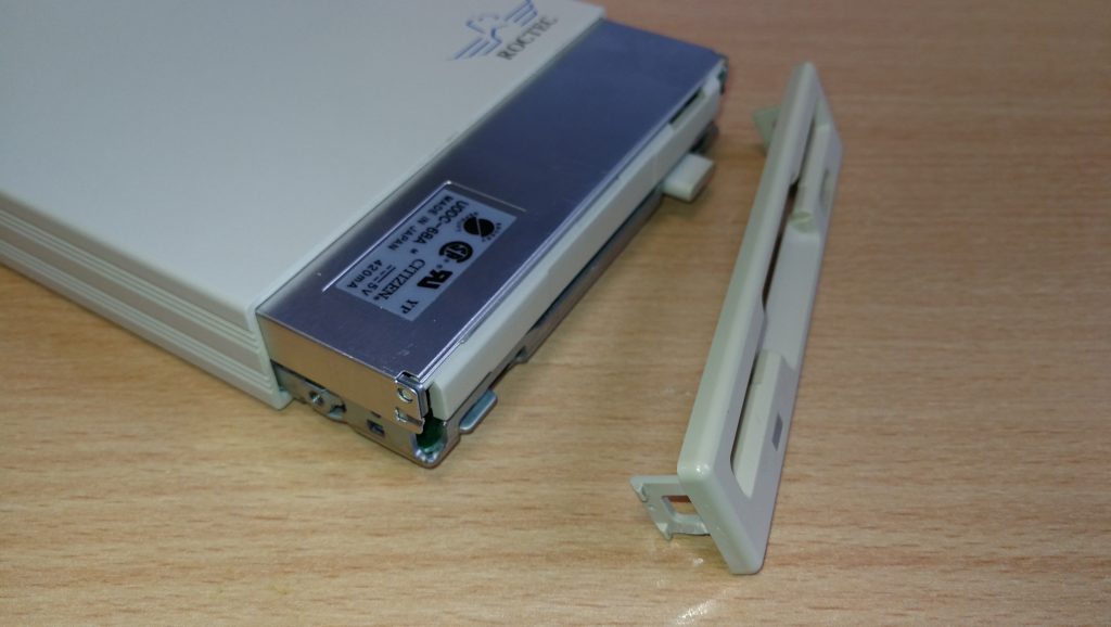
This particular drive case is made from a solid metal rectangular tube so you need to slide the floppy drive out. The aim here is to slide everything out of the BACK of the case. The first step is to gently slide the floppy drive forward out of the case far enough to detach the plastic fascia from the front of it. Unless you do this it won’t slide right into the case and out the back. There are 2 small tabs on each side of the fascia which you can gently bend with a small flat-bladed screwdriver and it will pop right off. Don’t force anything or it will break – it should come off easily.

Drive Fascia removed

Drive Fascia removed

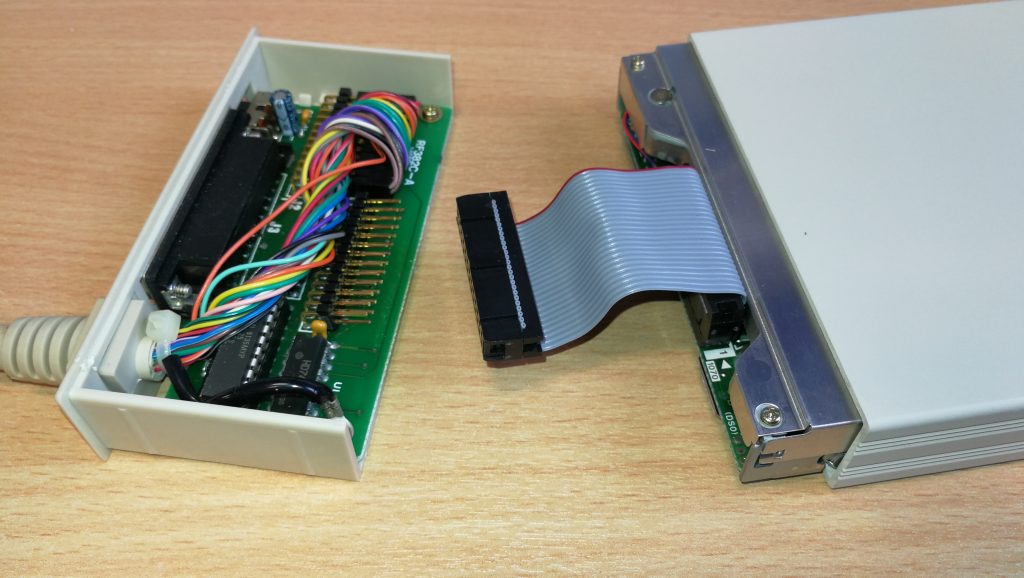
Now you need to prise the back part of the drive out of the case using something thin enough to slide into the tiny gap between the case and the backplate, I found the blade of my pocket knife to be perfect for this but be careful not to injure yourself or damage the plastic/paint on your drive! Once you’ve got it moving slide it out slowly (a slight side to side wiggle can help here). It will be attached to the floppy drive via a ribbon cable so keep going until you’ve got the floppy drive out too.

Roctec floppy drive detached

Roctec floppy drive detached from controller board

The floppy drive has a thin metal cover that protects the mechanical innards and it is held in place by some little tabs on the edges and a solitary screw at the back right (when viewed from the front).

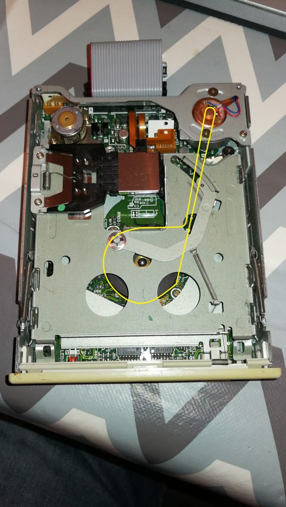
Roctec Floppy Drive Rubber Belt Path

Roctec Floppy Drive Rubber Belt Path

Replacing the Belt

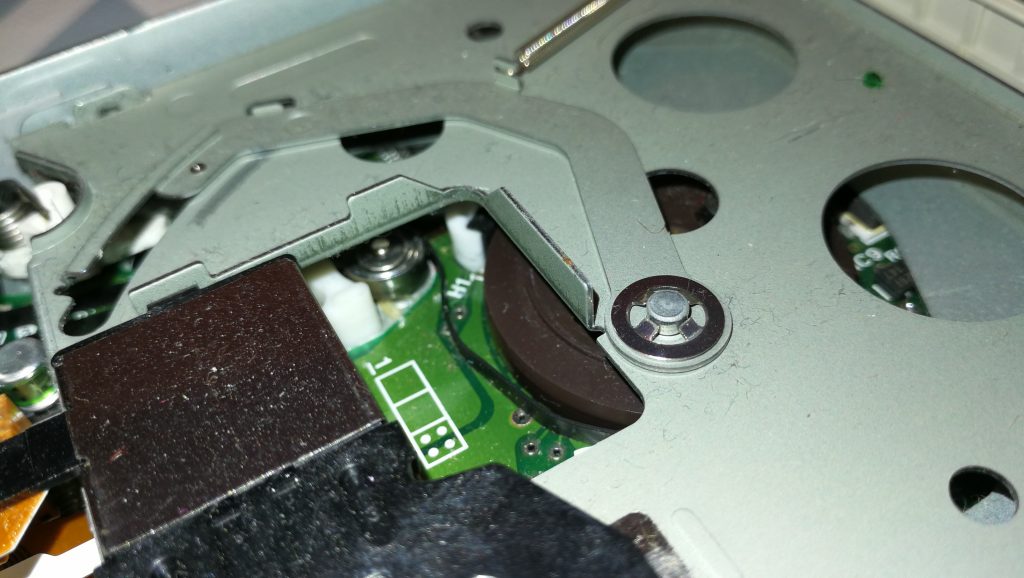
Once the top is off you can see the drive mechanism, motors, heads and so on. Carefully remove what’s left of the old belt with a pair of tweezers. Be careful not to touch the drive heads with anything metallic or you may damage them. The photo above shows the path the rubber belt follows, indicated by the yellow line.

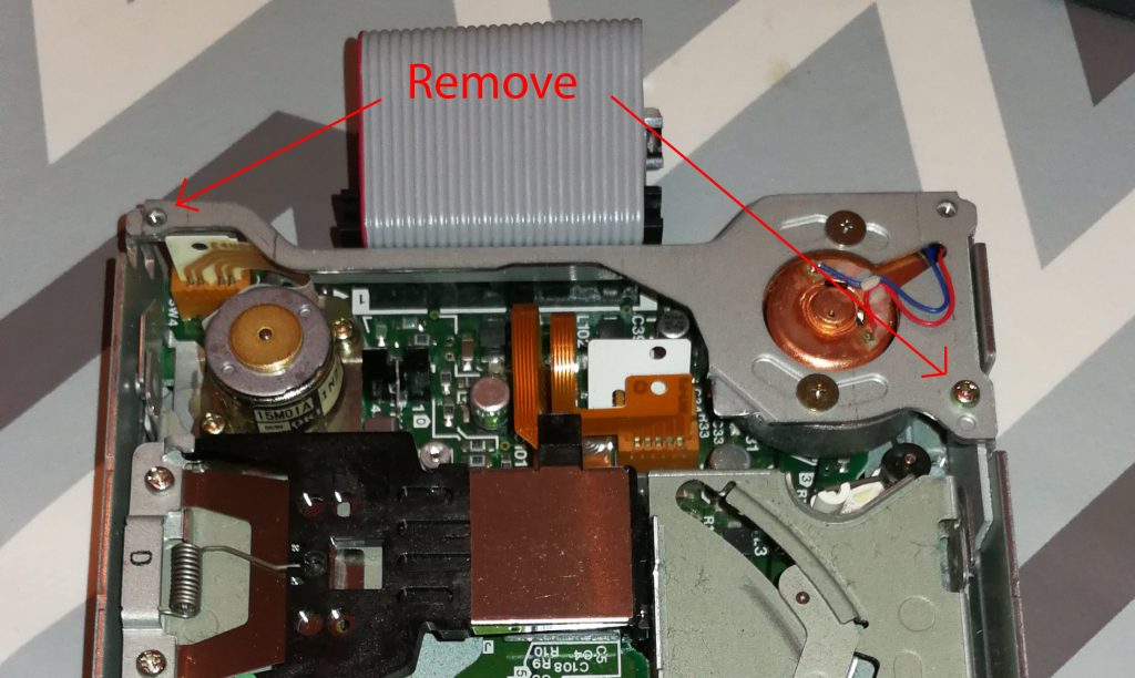
The next step is to remove the drive motor which is attached to a metal bracket that runs across the back of the drive. It is held in position by one screw in the far left corner and another on the right a few cm down from the corner. Don’t touch the two screws with the large flat heads either side of the motor. Be careful you don’t pull the bracket too much as there are two tiny wires connecting the motor to the circuit board here so be careful to support the bracket whilst you are handling the drive to replace the belt.

How to detach the motor and bracket

How to detach the motor and bracket

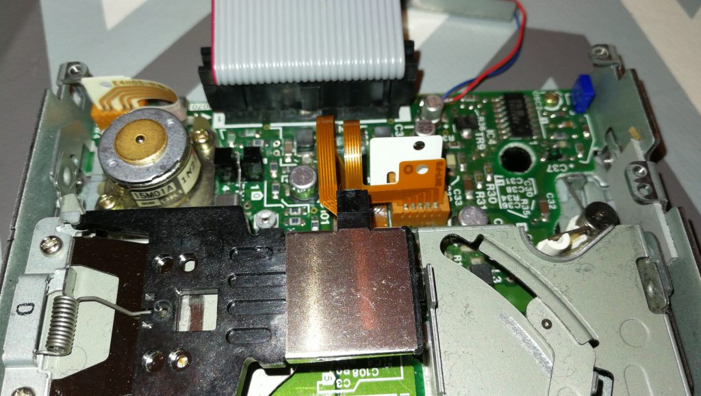
Drive motor and bracket removed

Drive motor and bracket removed

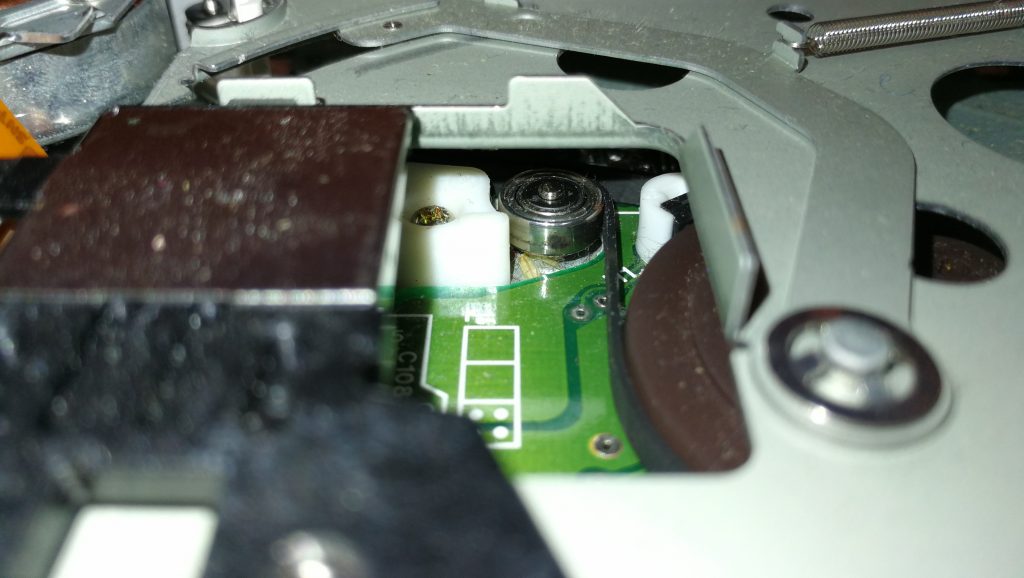
Once the bracket and motor are out of the way you can carefully thread a replacement belt around the large drive wheel, small tension wheel and keep a loop ready at the top right to go on the motor spindle. Follow the yellow path in the earlier photo and take your time as it can be a little tricky to get the belt into place. A small flat bladed screwdriver and a pair of tweezers are essential for this. Don’t forget the belt needs to thread behind the small silver pully wheel as this is what tensions the belt.

Close-up of the small tension wheel you need to thread the belt behind

Close-up of the small tension wheel you need to thread the belt behind

Once you’ve got it threaded around the wheels correctly you need to get the final loop onto the motor spindle. It helps if you grab the loop with some needle nosed pliers here and pull it taught with one hand whilst guiding the motor spindle into the loop with the other. Once this has been achieved (it may take a few goes as it’s quite fiddly) place the bracket back in place and rotate the large drive wheel slowly and check the belt stays on, is running where it should and isn’t fouling any components.

Look carefully through the tiny gaps in the top of the drive motor you should be able to see the motor armature slowly rotating as you move the belt. If it is then job  done, time to put it all back together! If it isn’t then don’t fret, just double check the belt is following the correct path, isn’t twisted anywhere and hasn’t slipped off any of the wheels.

Congratulations, your Roctec drive should now be fit for active duty for another several years now!

Changing a Boogie Board Battery

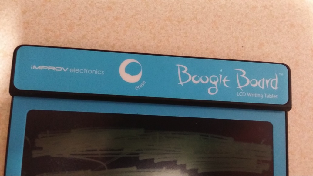
Boogie Board LCD Slate/Tablet

Boogie Board LCD Slate/Tablet

A couple of years ago I bought a cool looking gadget called a Boogie Board from Firebox. Intention was to attach it to the fridge-freezer and use it as a paperless notepad for shopping lists, reminders and so on. It has performed that job flawlessly until a week ago when it suddenly refused to erase the contents of the screen. To cut a long story short, the battery was flat and without any power the e-ink display (similar to the original Kindle) couldn’t be erased. The device is sold with a NON-REPLACEABLE 3V battery and is supposed to last for 50,000 screen wipes before losing charge. I’ve had the thing for not much longer than 2 years and even if it had been used and wiped every single day that would be less than 800 wipes, a figure massively short of the touted 50K. I’ve probably erased it once or twice a week so probably erased it 250-300 times, tops!!! When you consider that is cost me £30 and they expect me to throw it in the bin and get another one you can imagine I was not too pleased!

So, being a tinkerer and having nothing to lose if things went wrong I decided to open it up and see if there was anything I could do to salvage it. Turns out it is fitted with a normal 3v Lithium CR2032 Button Cell with the only complication being that it is soldered onto the small PCB inside. The good news is these can be purchased off eBay for a few pounds, complete with the solder tags – a much better prospect than throwing a perfectly good product in the bin and spending £30 to replace it! Incidentally, I did try my local Maplins but they don’t stock this type of battery..

I thought I’d share my exploits in case it can help anyone else in a similar situation.


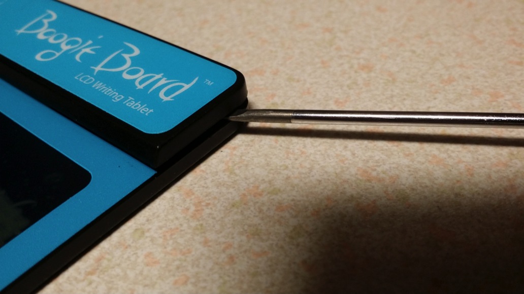
Prising the cover off

Prising the cover off with a screwdriver

First off, you need to remove the thick top strip (the bit that houses the erase button). There are no screws, it appears to just clip into place by means of four studs spaced across the width of the board. I was able to carefully prise this strip off using a very thin precision flat-head screwdriver, just be careful not to push the screwdriver in too far as you may damage the components inside.


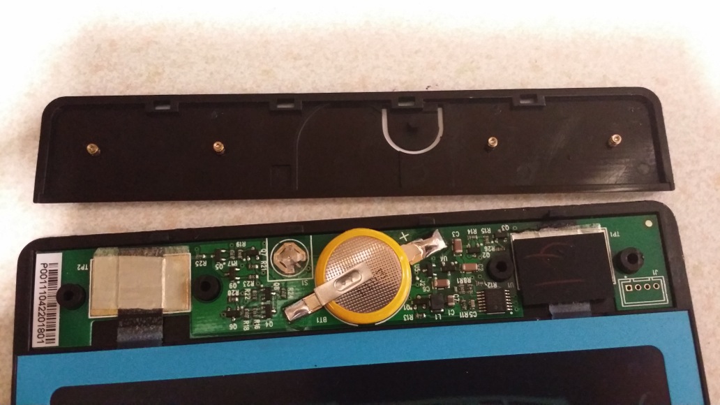
Boogie Board with cover removed

Boogie Board with cover removed

Once it is off you will be able to see the old battery in the centre, soldered to the PCB by means of two ‘tags’. You will need to de-solder the old battery to make way for the new one. Be careful though, I was a little ham-fisted and accidentally pulled away some of the solder pad on one side – luckily enough remained to allow me to continue.


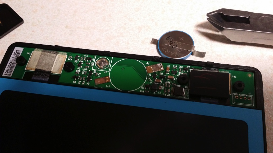
Old battery removed

Old battery removed

Here’s the PCB with the old battery removed.


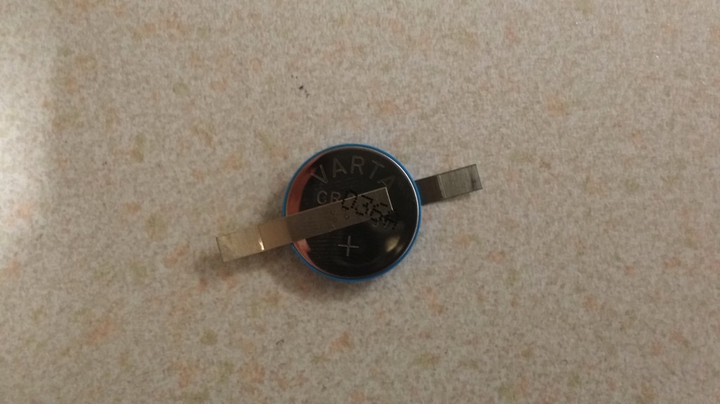
Replacement 3V CR2032 Battery

Replacement 3V CR2032 Battery

Here’s the replacement battery, complete with tags. You need to make sure you observe the polarity of the tags when you solder it back onto the PCB otherwise it may not work.


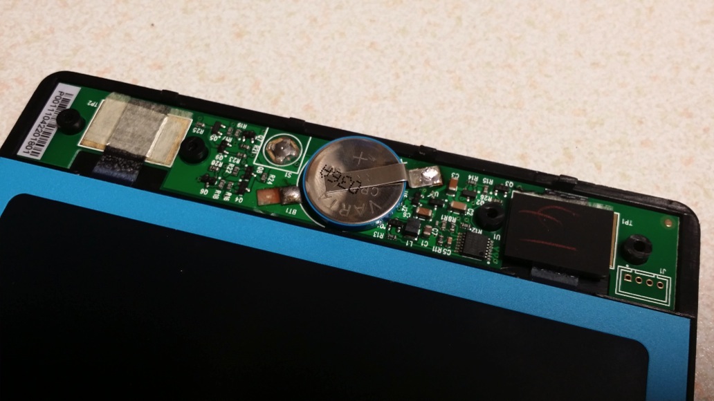
New battery fitted

New battery fitted

Once the battery is soldered back on, check the erase function now works by depressing the little silver switch to the top left of the battery. You can then replace the cover strip by simply pressing it back into place and you’ll have a fully working Boogie Board once more!


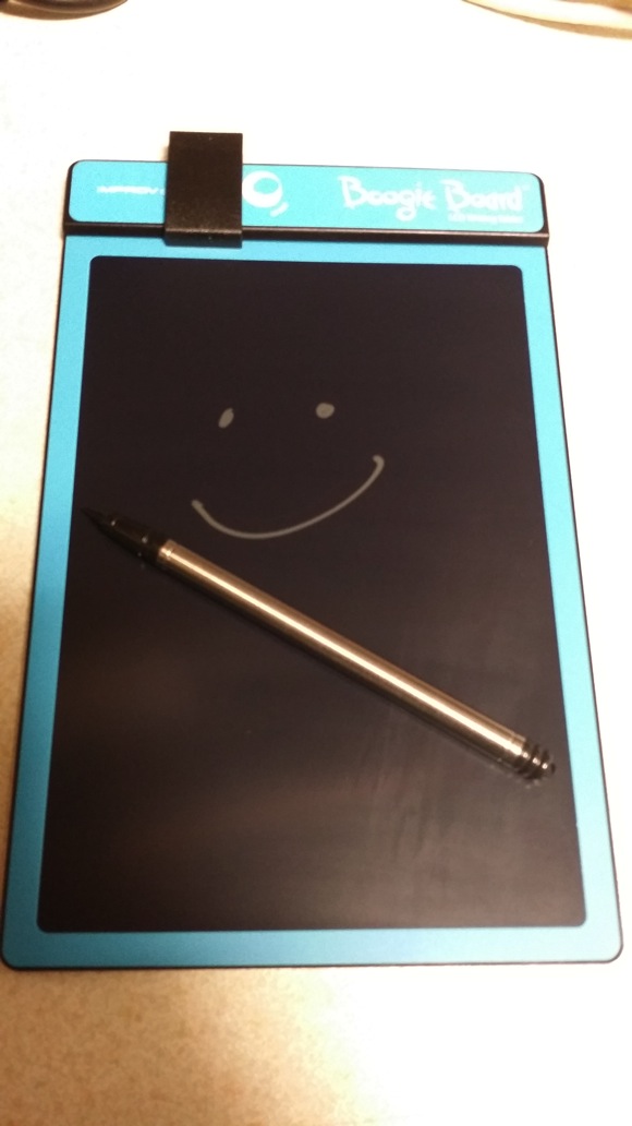
My fixed Boogie Board

My fixed Boogie Board