Having created the physical floppy disks in Part 1 of this guide it is now time to fit the IDE Compact Flash adapter and the 2 Kickstart 3.1.4 ROMS.
Fitting the IDE Compact Flash Adapter
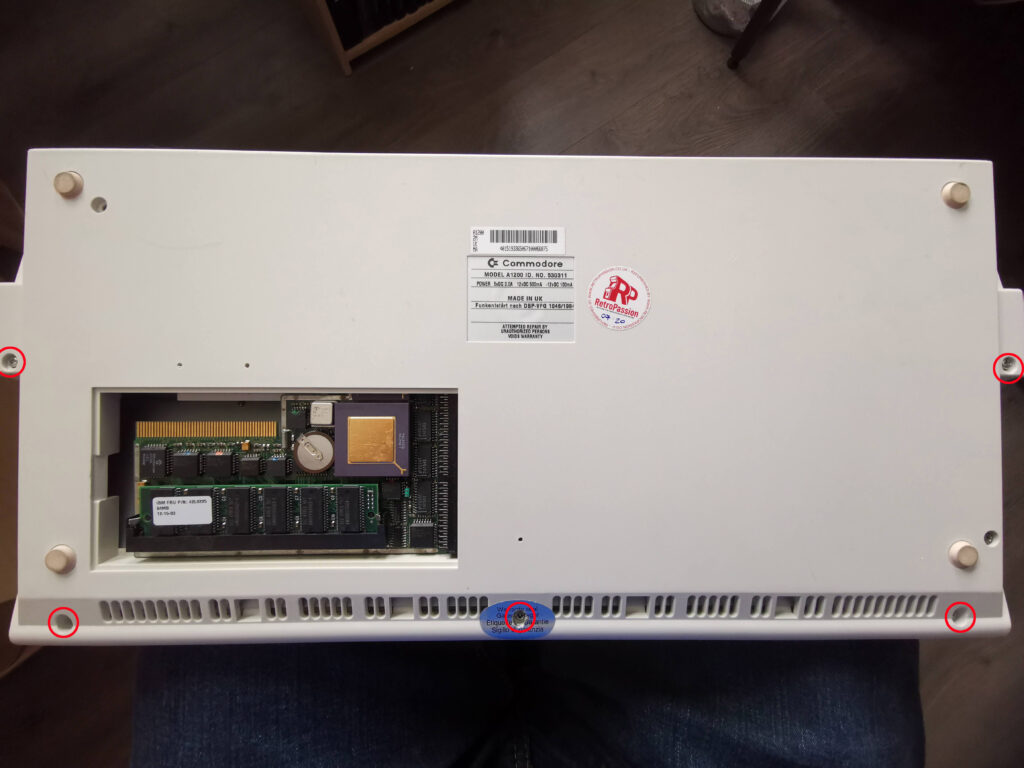
For this I needed to open up my A1200 to gain access to the mainboard.
Removing the top half of my A1200’s case was just a matter of turning it over and removing five screws. I’ve circled their locations in the photo above. There were three along the front edge and one each side of the case. The two rear edges of the case are held together by some little lugs and recesses in the case itself.
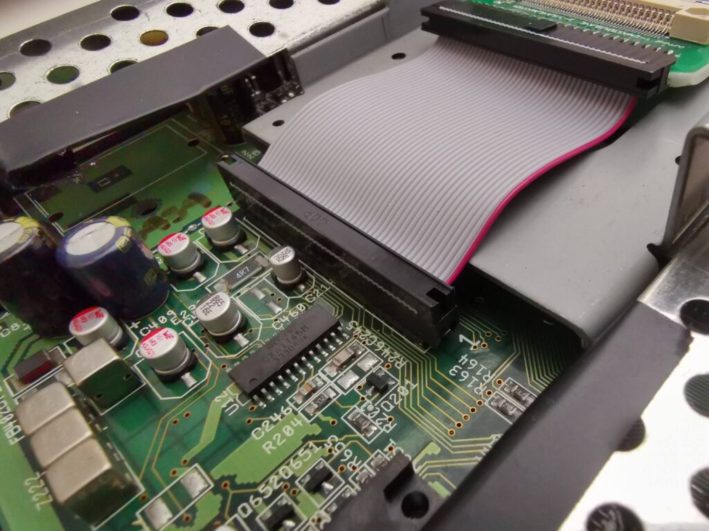
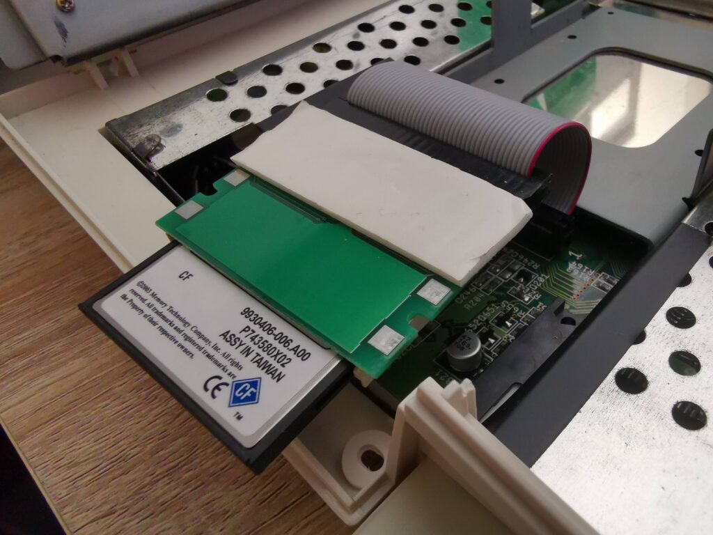
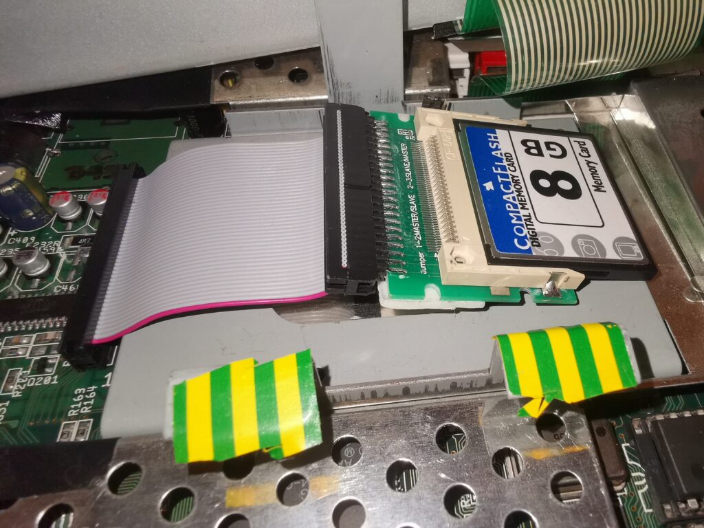
Fitting the IDE Compact Flash adapter simply involved fitting the 44 pin cable connector to the IDE header on the board. Notice how the coloured strip of the ribbon cable aligns with PIN 1 on the board. I chose an 8GB CF card for my install as Workbench 3.1.4 now natively supports large drives. However a smaller card would work just as well. I think my original A1200 had an 80MB (yes I do mean Megabyte!) drive back in the 90’s so 8GB is an insane amount of storage!
As the compact flash adapter has lots of solder pads on the base, I stuck a thick foam pad on the underside. This will ensure that the contacts don’t short out when sat on top of the metal drive bracket. (This drive bracket would have been used to house a 2.5″ IDE HDD back in the day).
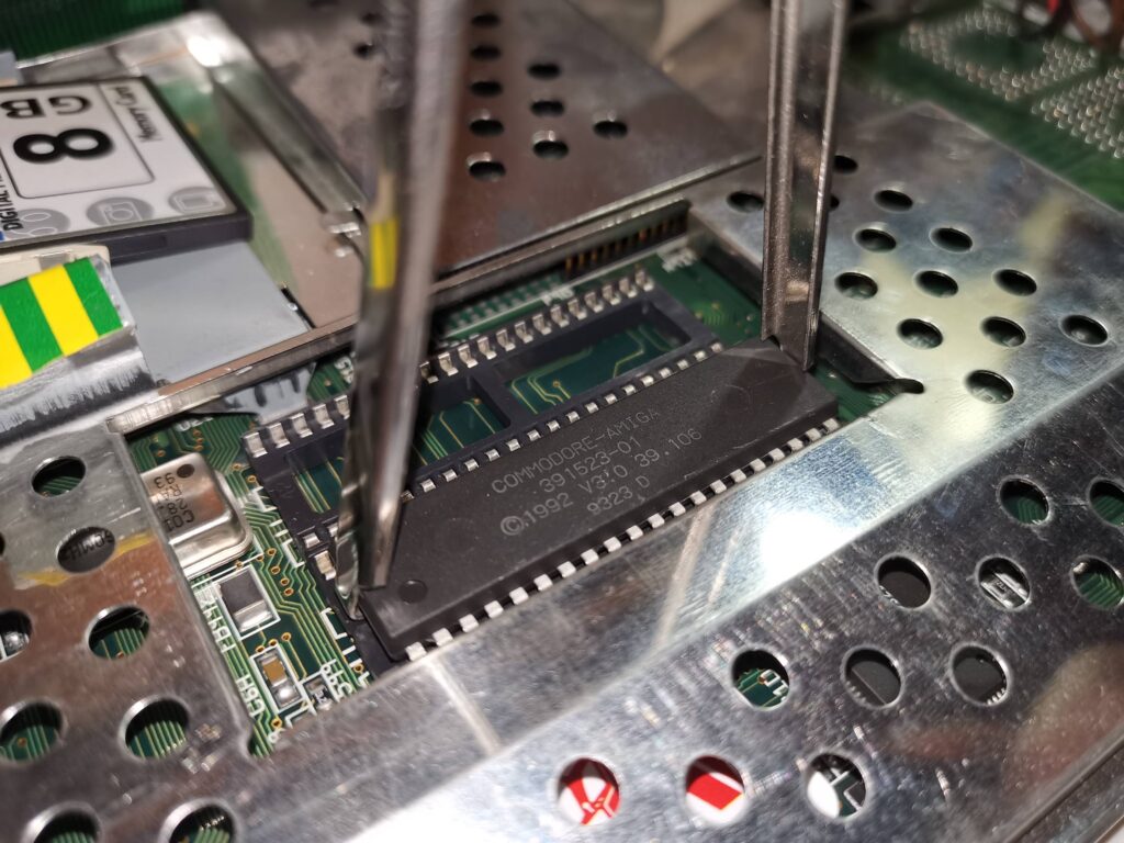
Removing the old Kickstart ROMS
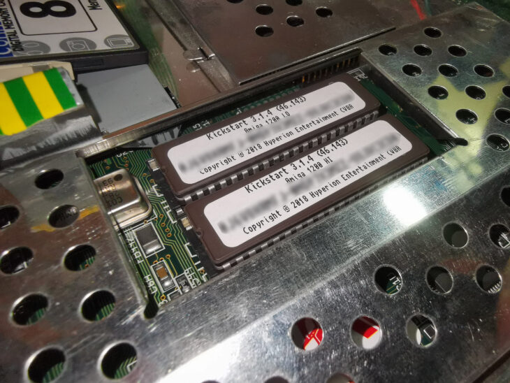
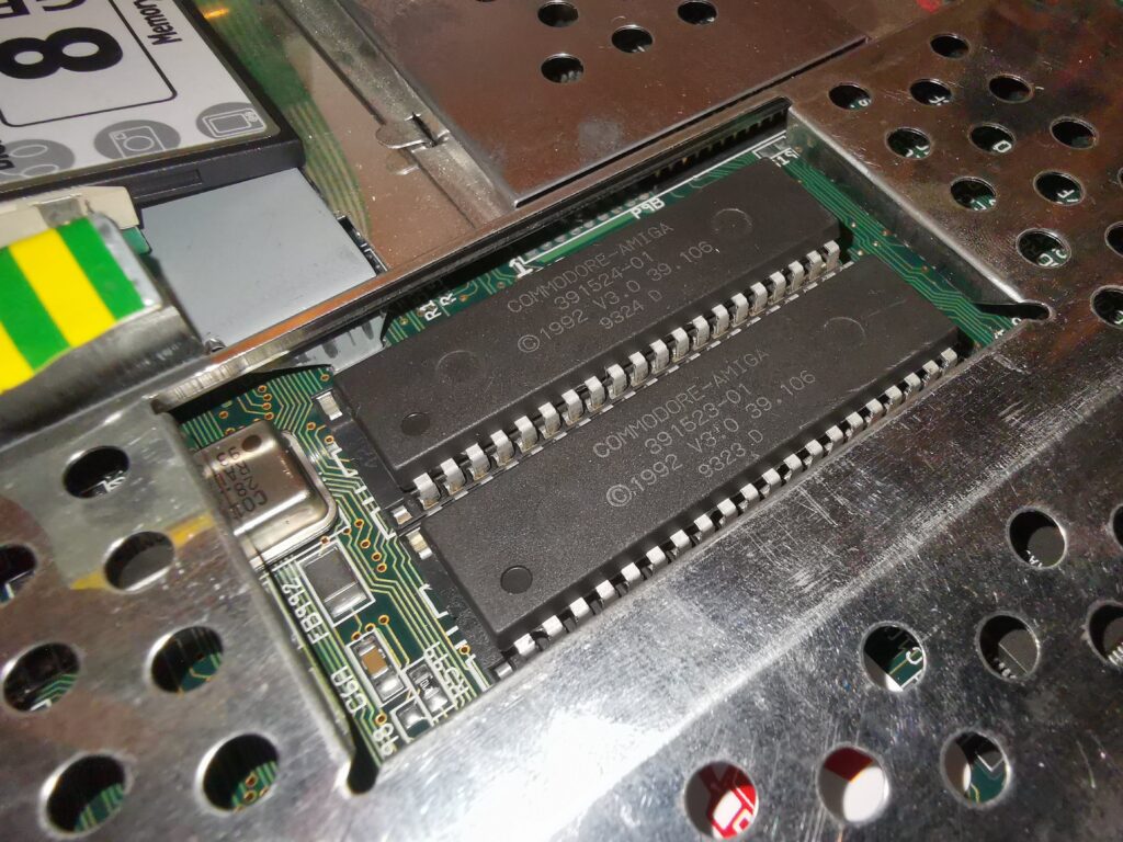
Luckily the Kickstart ROMS have their own little cut-out in the metal RF shielding so there is no need to remove the shield to access them.
I used my trusty chip puller to remove these, gently alternating pressure from one side to the other until they popped out. You could use a small flat bladed screwdriver to do this. Make sure to alternate from side to side, lifting the chips one millimetre at a time so you don’t bend the pins. If you want to make life even easier, use an old screwdriver and bend the blade 90′ at the end to make getting it under the chip easier.
Fitting the new Kickstart ROMS
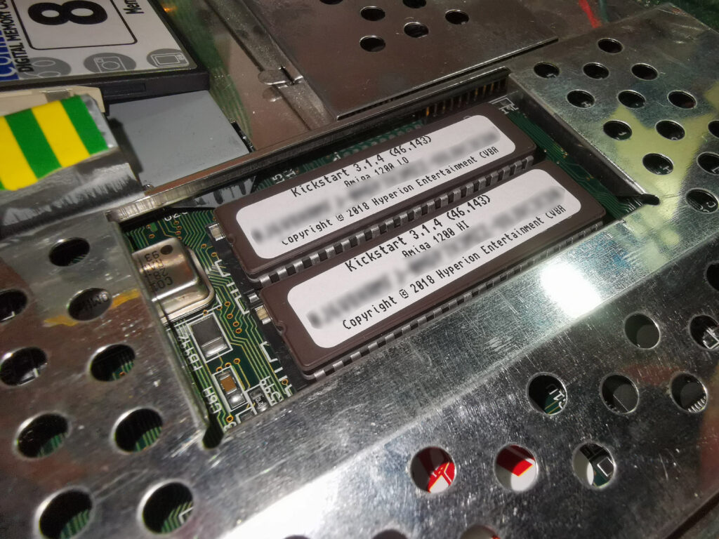
With the old ROMs removed it was time to fit the new ones. After making sure the pins would line up OK (they were splayed out a little too far) I began to fit them.
It’s vitally important they are fitted correctly and besides the usual static precautions there are three things to watch out for.
- The chips have to go in the right sockets. The chip marked as ‘HI’ must go in the front slot. The chip marked ‘LO’ must go in the rear slot.
- The chips must be oriented correctly. The end with the notch must be fitted so that it is on the same side as the notch in the socket.
- The sockets have 42 pins whereas the chips only have 40! You must make sure to leave the 2 pins on the left side of each socket empty.
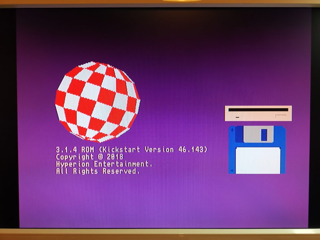
Thankfully testing the ROMS is pretty straightforward. Flicking on the power should display a brand new boot screen. That boing ball is definitely new! You can also see the updated ROM version and copyright message.
That concludes Part 2. In Part 3 I will deal with partitioning and formatting the Compact Flash card.
Discover more from Lyonsden Blog
Subscribe to get the latest posts sent to your email.

Steven,
I am very happy to come across your blog. I just got my first Amiga last week (August 2020) and am just starting out. I got an Amiga 4000 on eBay. I too got my box from Ireland and just got on the Hyperion Website to download the adf files. Boy do I have a lot to learn about AmigaOS!
Keep your posts coming!
Frank Rizzo
Buffalo, New York
Congratulations on getting the A4000 – pretty much the pinnacle of Amiga models!
I’m still learning myself or should that be re-learning? All good fun though. Hope to have the 3rd part covering the Workbench 3.1.4 install up by the weekend.