I’ve wanted an Indivision AGA Mk3 flicker-fixer for quite some time but have been stymied by a combination of Brexit and Covid-19. Individual Computers actually halted all shipments to the UK in December 2020 as a direct result of this situation. Undeterred, I kept checking the situation periodically to see if it had changed. Sure enough, towards the end of April I saw the news I’d been waiting for. Shipments to the UK were back on! I quickly ordered myself one and waited patiently for it to arrive.
Happily I didn’t need to wait for long as it arrived within a week and with no extra fees to pay too! Needless to say it was taken straight into my man cave to open it up!
Unboxing
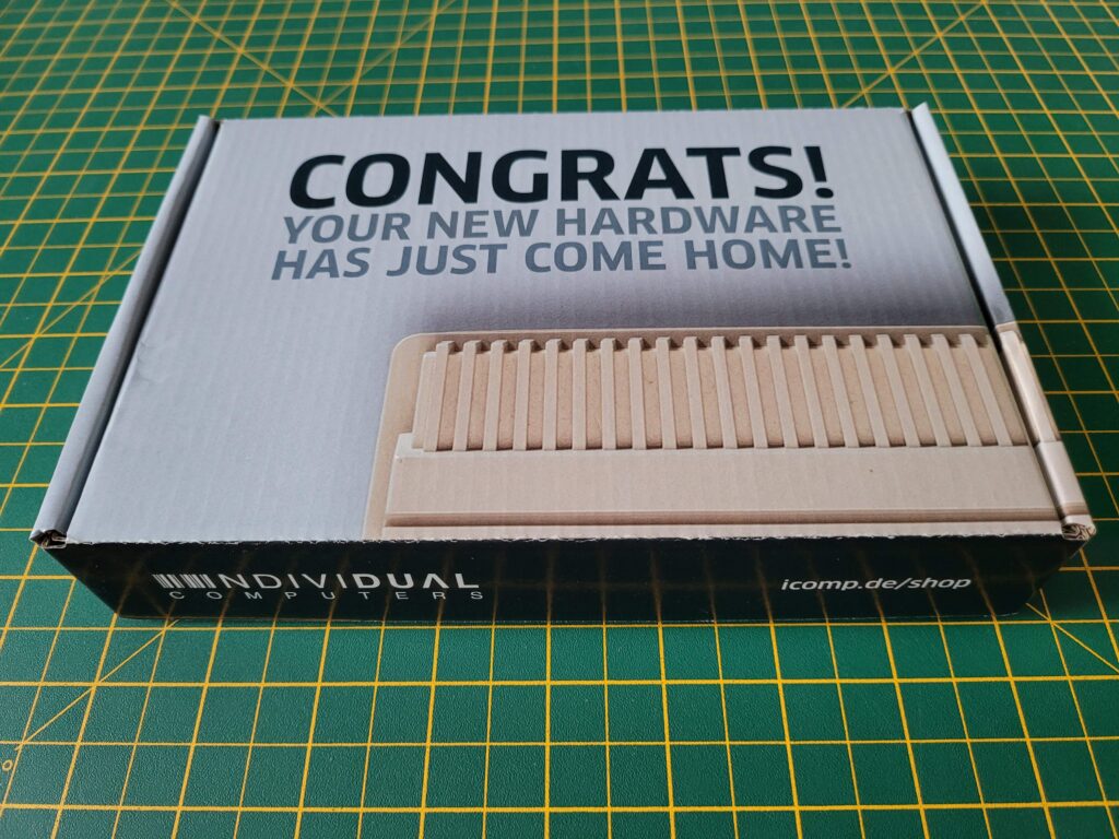
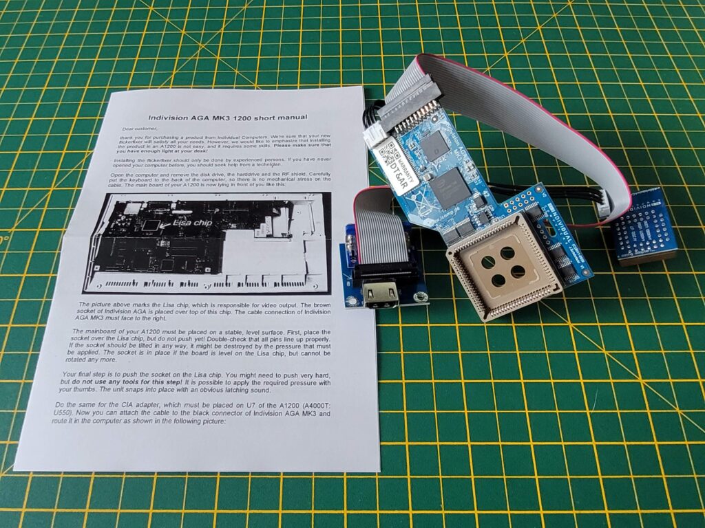
Inside the attractive cardboard box was the flicker-fixer, a single mounting screw and an instruction sheet.
The included instruction sheet wasn’t brilliant if I’m honest as the print quality was very poor. Thankfully there’s a much better version online on the icomp.de Wiki here.
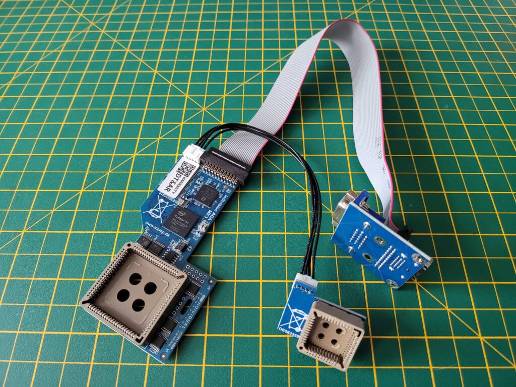
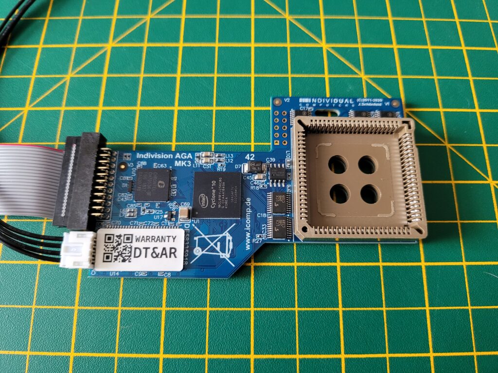
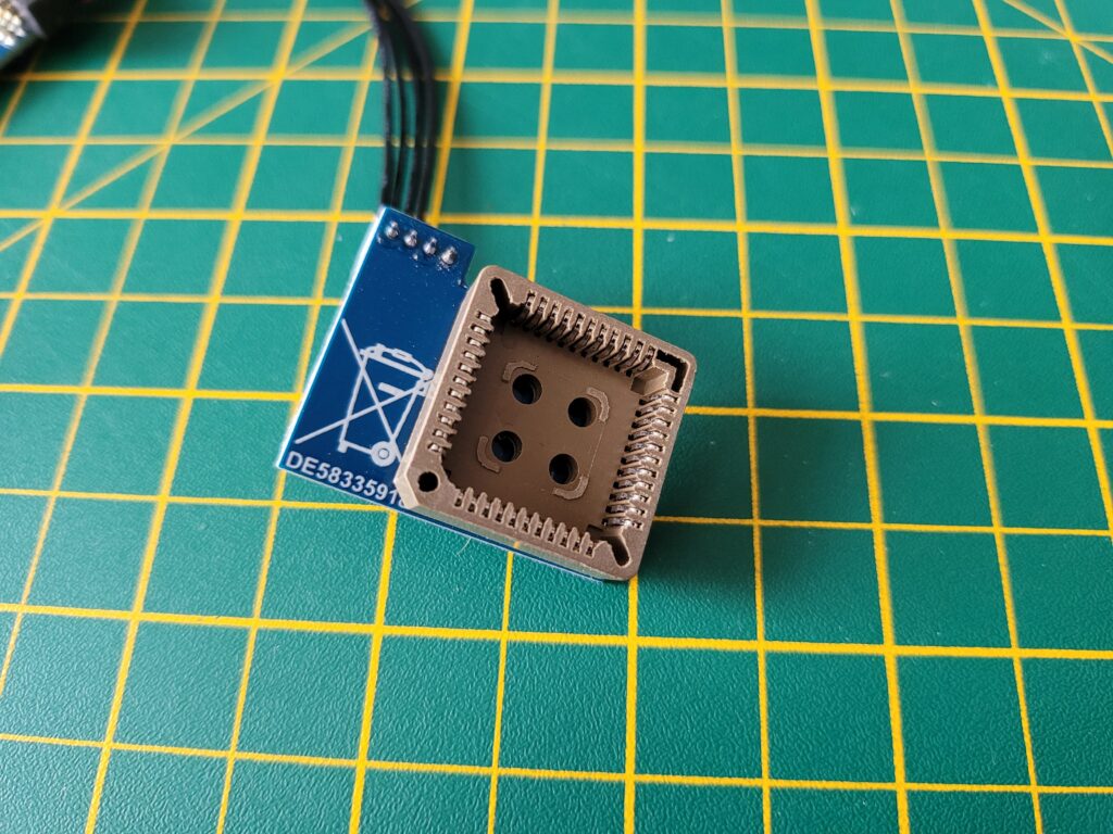
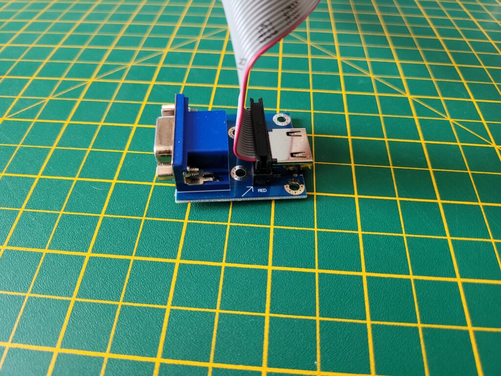
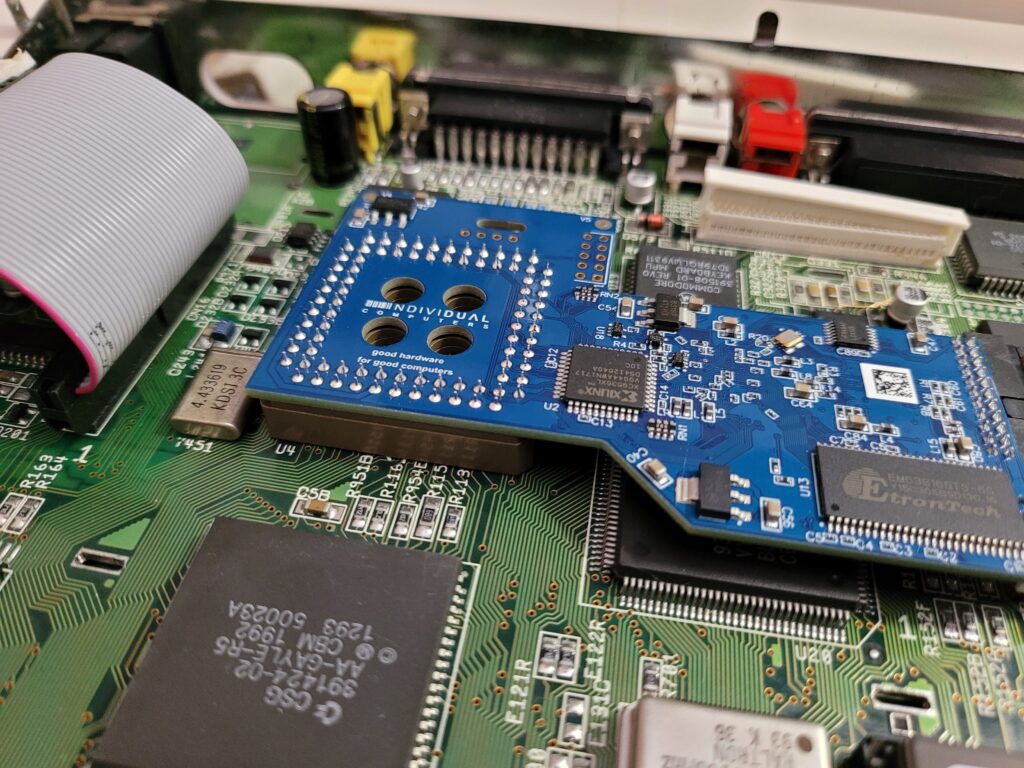
The Indivision AGA Mk3 consists of three main components. The largest circuit board is the actual flicker-fixer whilst a smaller board handles keyboard signals. Finally there is a VGA/HDMI connector attached by means of a ribbon cable to the main board.
The main flicker-fixer board (above) features a large socket which allows it to connect to the Amiga 1200’s Lisa graphics chip and perform it’s scan-doubling and flicker-fixing duties.
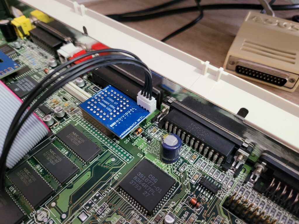
The smallest board has a socket that connects to the U7 CIA chip. This allows it to check for a specific combination of key presses to bring up the ‘Live Edit mode’.
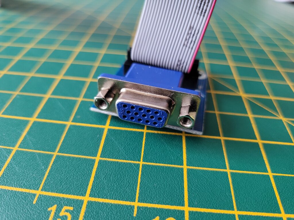
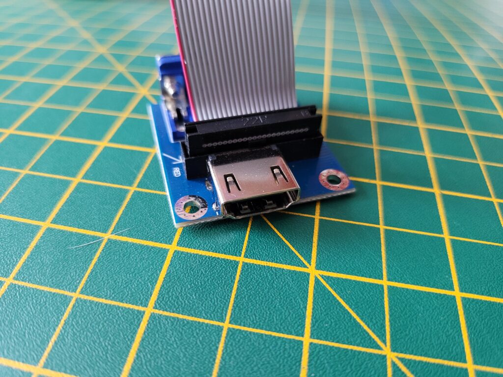
The Indivision AGA Mk3 supports both VGA and HDMI monitors by means of a board that incorporates both types of connectors on it.
You simply install the board with your preferred connection method facing outwards. It’s intended to fit in the A1200’s expansion port and a single screw is supplied to securely attach it to the bottom of the case.
Preparation
The very first job was to remove the A1200’s metal RF shield which was blocking access to the areas of the mainboard I needed to get to. This necessitated removing the floppy drive, a couple of screws along the front edge of the board and bending up several little tabs all around the shield. Once I’d done this I was able to lift away the shield with only a little bit of leverage from a screwdriver required along the back edge. This resistance was most likely the result of the small amount of corrosion present on my RF shield.
With the RF shield removed I now had unrestricted access to the entire A1200 motherboard. I don’t think I will be putting it back on any time soon as it would need modifying to fit around the Indivision. Besides, with it permanently off I have easy access to the board for future projects.
Board Revision
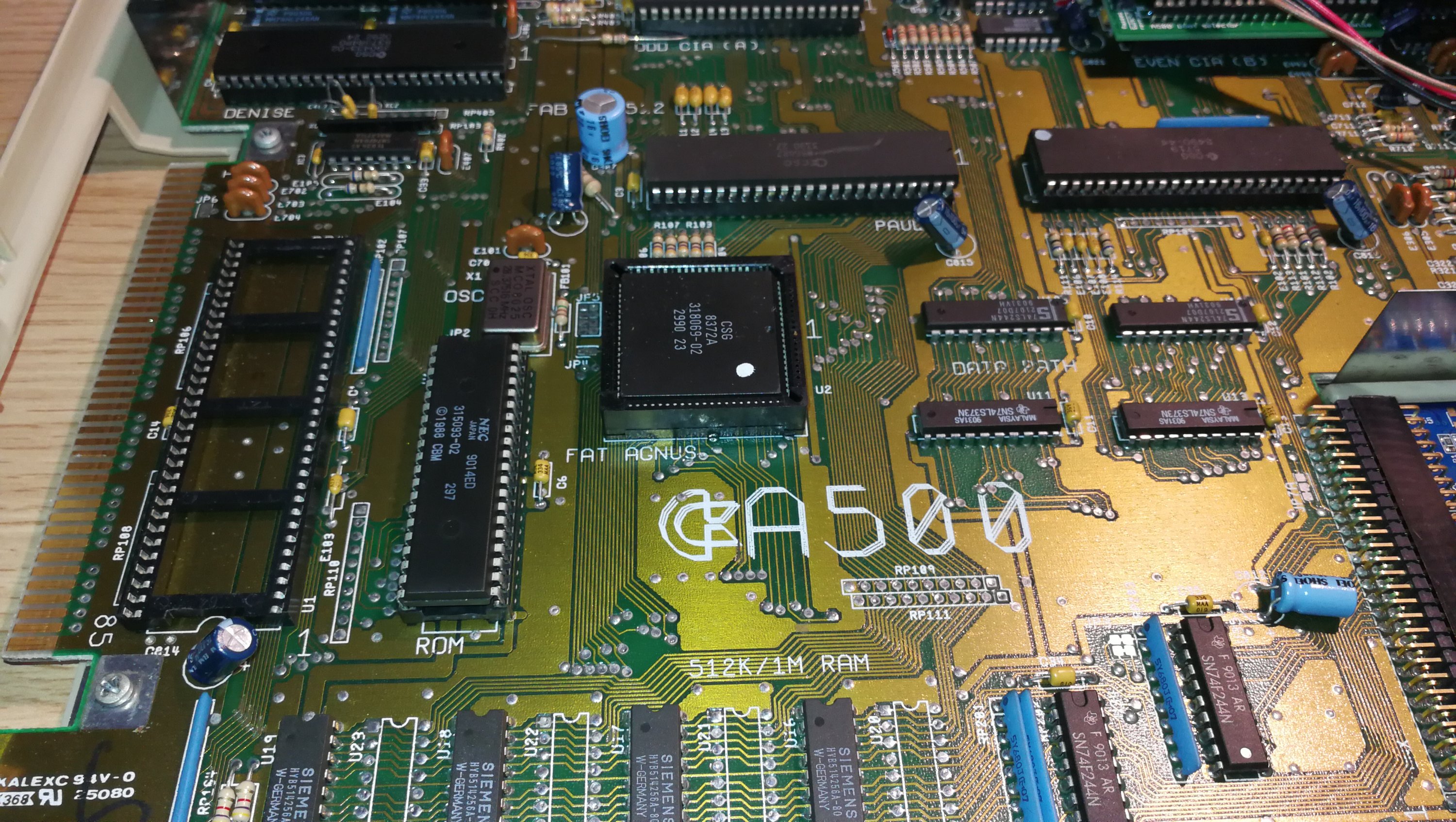
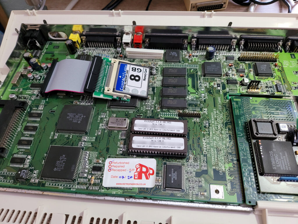
Interestingly, with the shield off I could now see the information printed on my A1200’s motherboard. It was identified as being a Revision 1D4 board. These boards are also recognisable by the fact that the mouse port isn’t actually part of the board itself but rather connected to it via a ribbon cable. Earlier revisions had the mouse port on the board itself whilst the later R2 motherboard had the mouse port on a separate little board. My 1D board also has a half-width clock port header whereas earlier boards had full length ones.
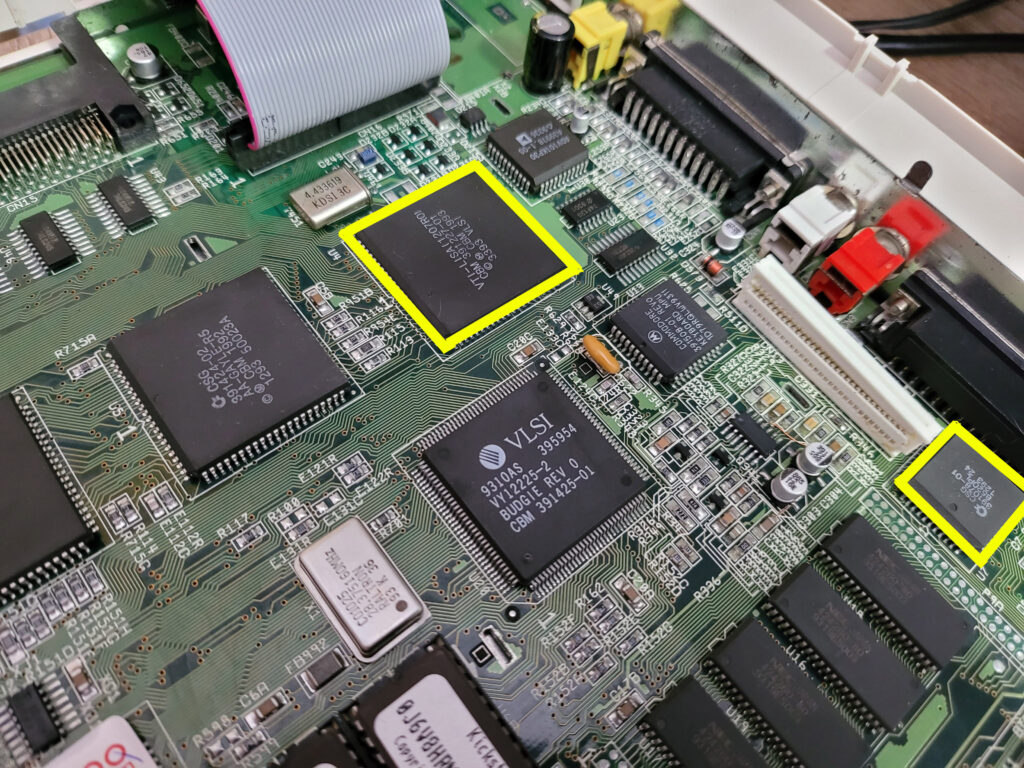
The chips outlined in yellow show where the Indivision AGA Mk3 connects to the A1200 motherboard. The larger chip is Lisa and the smaller one the U7 CIA.
Installation
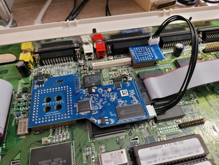
Fitting the main Indivision AGA Mk3 board was fairly straightforward as no tools or clips are required. The board employs an empty socket to latch onto the Lisa chip and grip it tightly. I made absolutely sure that it was aligned correctly and then carefully pressed it into place. The instructions make it very clear that it must ‘click’ into place to be properly installed and this does require quite a scary amount of pressure to be applied. After a few moments of applying steadily increasing force to the board it did eventually snap into place with a very satisfying ‘click’. I then made a visual check all around the Lisa chip to ensure it was seated completely flat.
The next stage was to fit the U7 CIA chip connector. I had to consult the wiki to check the location and orientation of this as the instruction sheet was so murky I couldn’t make it out. It’s quite a tight fit next to the keyboard connector but at least it didn’t require as much pressure this time.
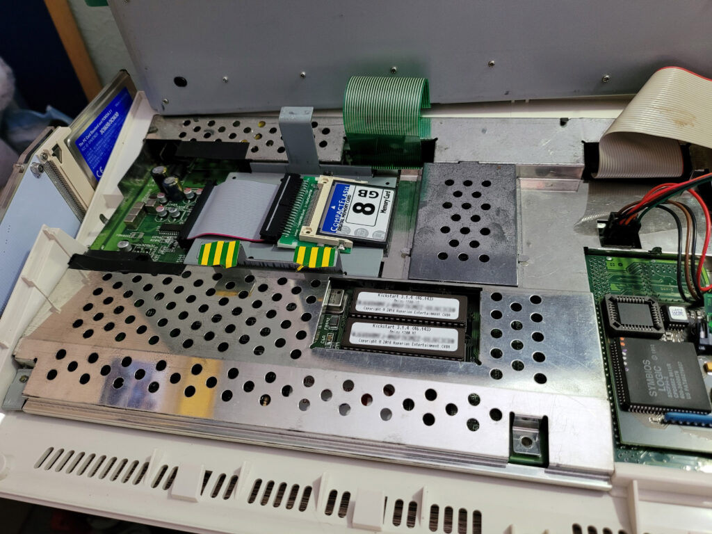
The final installation step was to find a home for the HDMI/VGA sockets. In an ideal world the connectors would fit into the expansion bay beneath the floppy drive but that space is already occupied by my Blizzard SCSI port. My A1200 has had the RF Modulator removed and I had hoped it would fit there but unfortunately there was insufficient width to accommodate it so this location was out too.
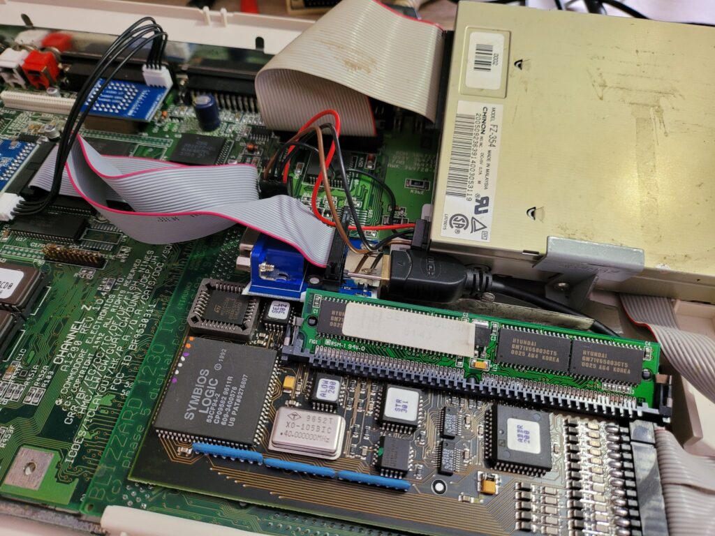
My placement of the HDMI/VGA connector between the trapdoor expansion slot and the floppy disk drive.
After trying a few places I settled for a position between the floppy drive and the trapdoor expansion bay. It fits there nicely and allowed me to run the HDMI cable under the case and up through the trapdoor. I applied several strips of insulating tape to the base of the HDMI/VGA board to prevent any possible short-circuits. It’s not the perfect solution as I’m unable to unplug it without removing the case but it’s an acceptable compromise. I made sure to use a nice thin, flexible HDMI cable which made routing it through the trapdoor and underneath very straightforward.
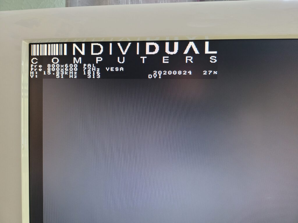
It was finally time for the moment of truth – the big switch on. After powering on my A1200 I waited patiently and after a few tense moments an Individual Computers overlay appeared in the corner of the screen. Having seen proof of life – it was now time to see what it could do!
Configuring a 16:9 Workbench Screen
I downloaded the HighGFX screenmodes off Aminet and also the Indivision config tool off the icomp.de website and set to work creating the perfect Workbench screen…
There are two sides to this – the Amiga screenmode and the Indivision mode. The way it works is the Indivision detects the screenmode the Amiga is using and then maps it to one of it’s built-in preset (monitor friendly) output modes. With the Indivision Config tool you are able to create your own modes too and there’s a plethora of settings to tweak if you have the patience. Thankfully the preset modes cover most of the common Amiga screenmodes so most people will probably be fine with what’s supplied ‘out of the box’.
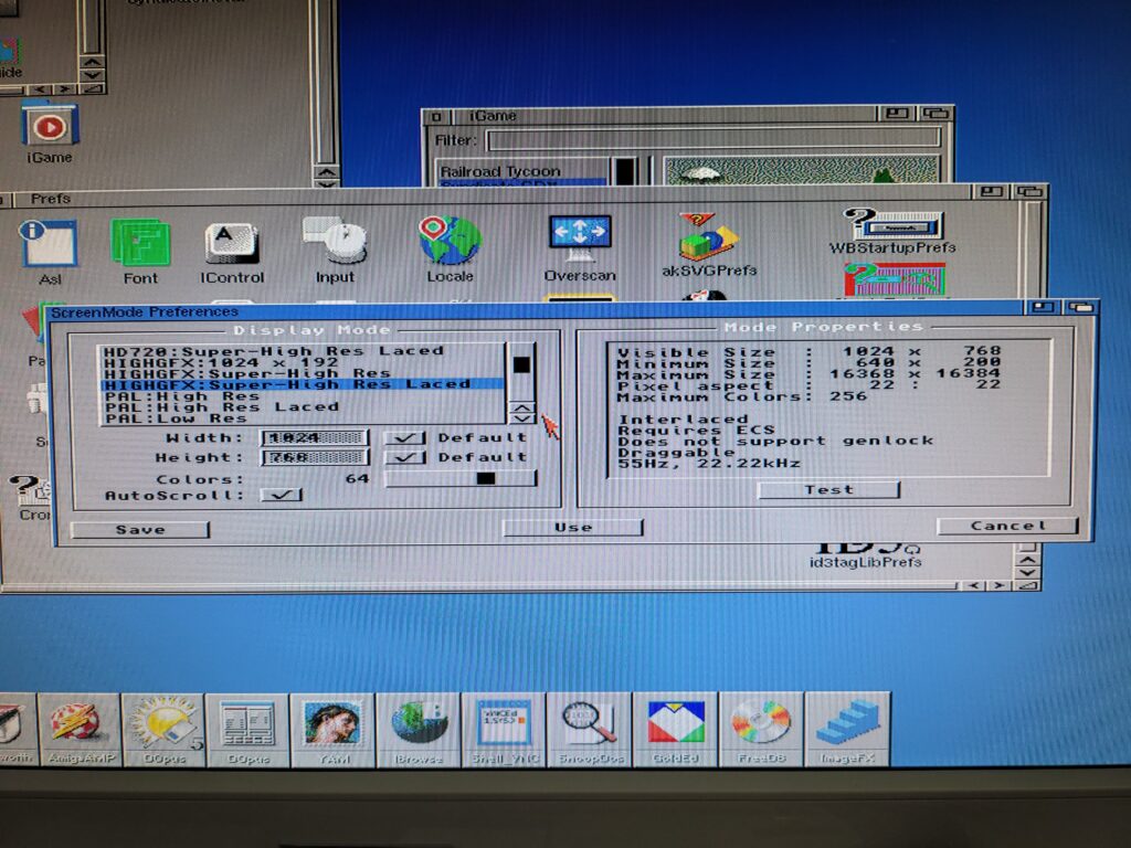
Back to my perfect Workbench screen… I spent the next few hours fiddling about trying to get a proper 16:9 mode working on my HDTV with a native resolution of 1366×768. I was trying to get the HD720 HighGFX mode working which should have given a perfect 1:1 pixel aspect whilst also utilising the entire screen width. However I just couldn’t get any combination of Amiga screen mode and Indivision settings to display correctly, even after painstakingly tweaking the 1280×720 preset to perfectly fill my monitor screen.
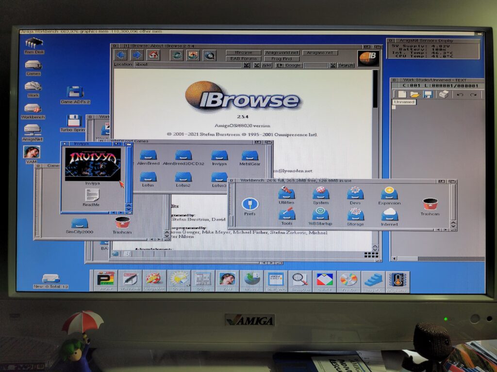
In the end I settled on the HighGFX Super High Res Laced 1024 x 768 mode which worked perfectly as the Indivision matched it to an existing VESA 1024×768 mode. The image fills my entire screen and is super crisp and vibrant thanks to the all-digital nature of the HDMI output. The only slight niggle is the image is very slightly stretched horizontally. This is because although the Amiga screenmode has a 1:1 pixel ratio – it’s intended to be used on a 4:3 monitor screen, not 16:9. However it’s by no means a deal-breaker and having such a massive (by stock Amiga standards) screen makes Workbench even more pleasurable to use.
One day I will have another go at creating a perfect 1:1 16:9 Workbench screen but for the time being I’m satisfied with what I have now.
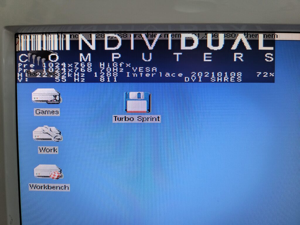
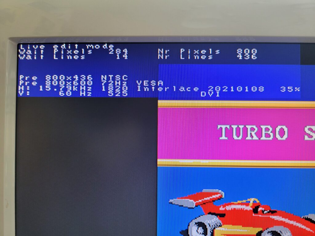
Indivision overlay showing both the detected Amiga screenmode and the preset mode being used to display it.
Configuration Tool
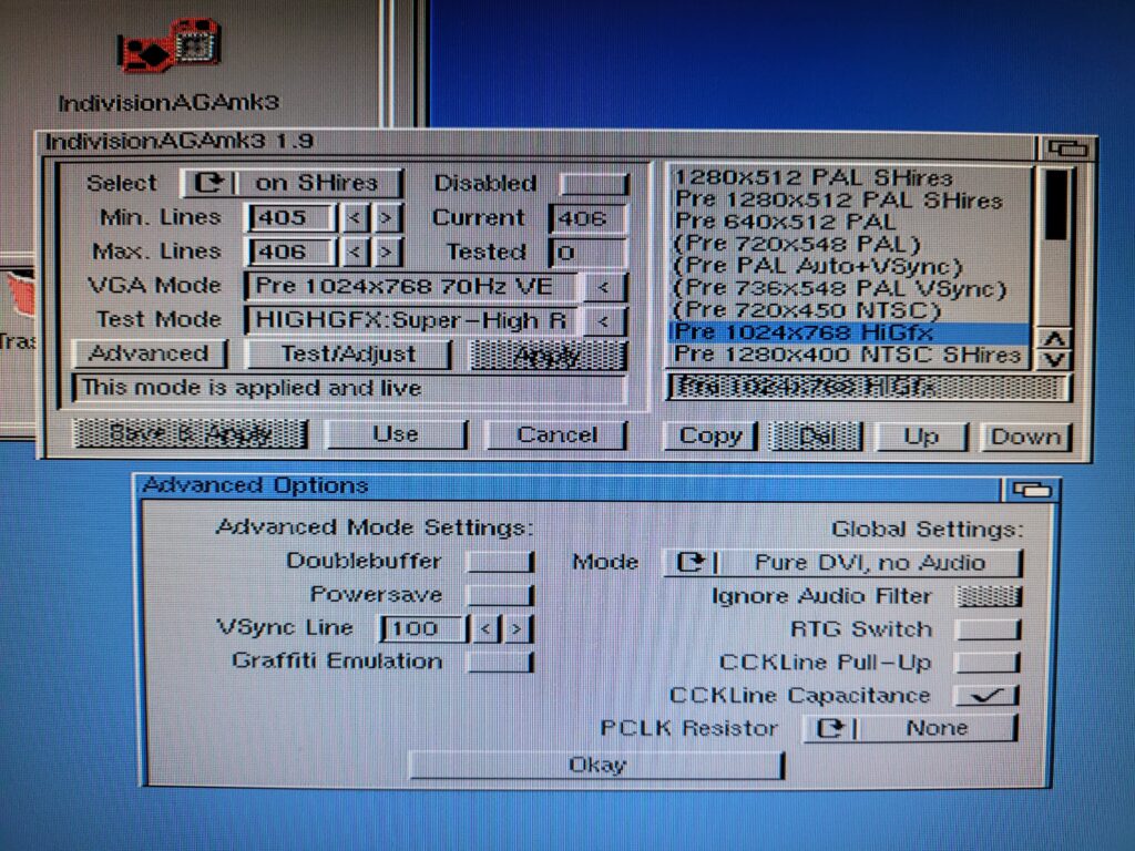
The card has its own dedicated configuration tool that you install to your Preferences folder. It allows you to create, test and tweak an almost limitless array of screenmodes, whether they be for productivity apps or PAL/NTSC games. Hidden away in the advanced section there is also an option to route audio through the HDMI cable too if you have a TV/Monitor that has speakers. I have my sound routed through a Bose Soundlink Mini as my TV speakers are pretty wimpy but this would be a great option otherwise.
Glitch in the Matrix
I did notice an issue after using the Indivision card for a few hours – I was seeing some random flickering pixels on my screen. It got worse as time went on, and my Amiga was getting very warm too, much warmer than it would normally do. Naturally I immediately thought there was a fault with the card but after I RTFM again I discovered that this is actually quite a common issue and isn’t a fault at all. I was able to eradicate it completely by using the config tool and enabling ‘CCKLine Capacitance’ from the advanced options. I’m not going to pretend I understand what this does but it definitely fixed the issue for me. There are other settings that can fix other glitches too but thankfully this is the only issue I came across. I am still not entirely happy about the extra heat it generates but I intend to sort that with a few upgrades very soon.
Reports of my death have been greatly exaggerated
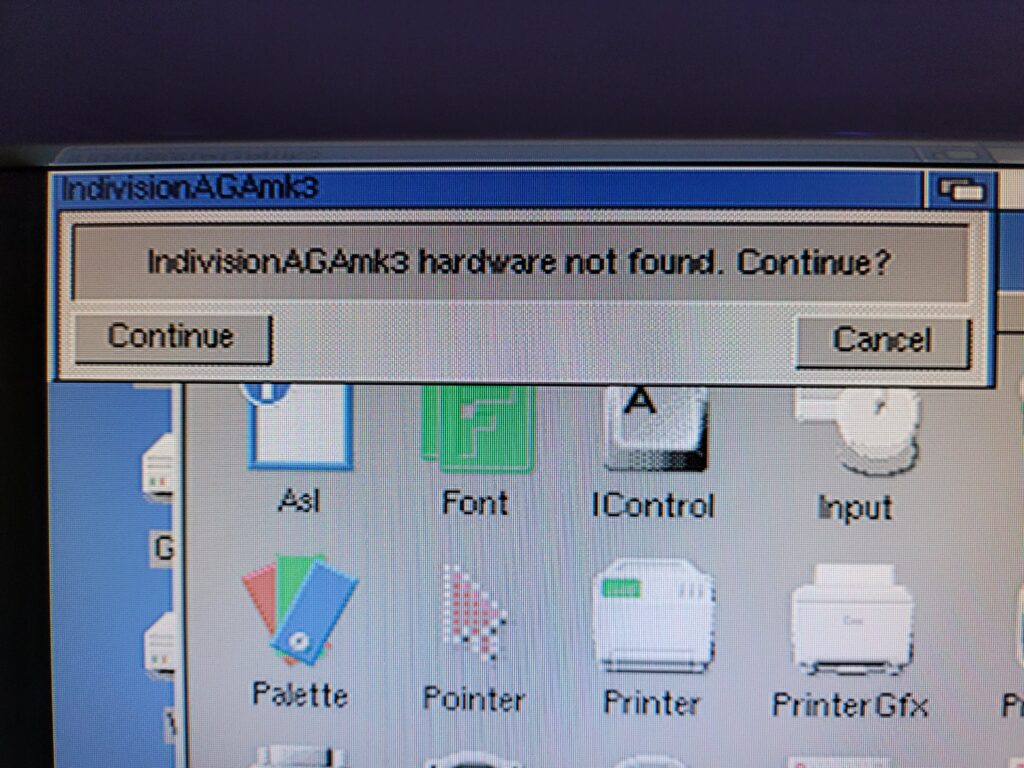
The Indivision card also tried to fake its own death at one point. I’m not entirely sure what happened but I had been messing around with the ‘live edit’ feature and the next thing I knew the Indi was no longer being detected. To make matters worse when I rebooted my Amiga it was using a screen mode that my monitor could not display so I couldn’t even see the screen. I tried removing the card and re-seating it but it still refused to work.
Now by this point I honestly thought it was dead and I’d have to return it. Then I remembered about the Rescue Disk recommendation I’d seen on the website. Amazingly I had read this and actually bothered to create one! I popped it in the drive, rebooted and after what felt like an eternity my Amiga booted up again and the card came back to life. I’ve never been so glad that I bothered to follow a set of instructions for once! I’m guessing I corrupted it’s firmware somehow and the repair disk re-flashed it but the main thing was my card wasn’t broken.
Live Edit Mode
Speaking of the ‘Live Edit Mode’ this is a utility that can be displayed at any time (even during a game) by holding down Left Shift, CTRL and Tilde. The fact this can be invoked at any time is thanks to that connection with the U7 CIA chip which allows it to detect the key-presses.
Whilst this mode is active you can move the on-screen image around your monitor with the mouse. You can also resize it whilst holding down the left mouse button in both the vertical and horizontal directions. This is a really useful feature and allows you to deal with any screenmodes that don’t have presets in the Indivision’s configuration. Once you’re happy with the screen layout simply press Tilde to exit Live Edit mode and ‘keep’ your adjustments. Whilst these ‘Live’ changes are not permanent by default (they are lost when power-cycling) there is an option to store them later in the config tools should you wish to.
In the example above I used the Live Edit mode to force Cannon Fodder to fill the screen of my 16:9 TV and remove all the black borders.
Do Adjust your TV Set
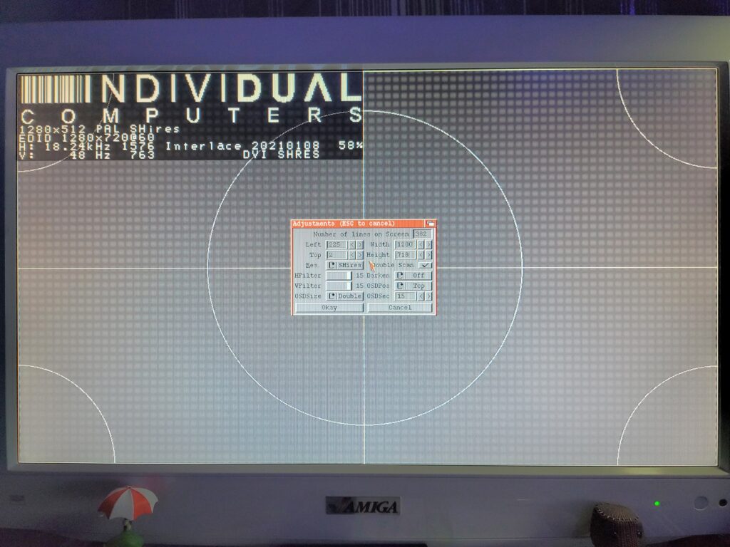
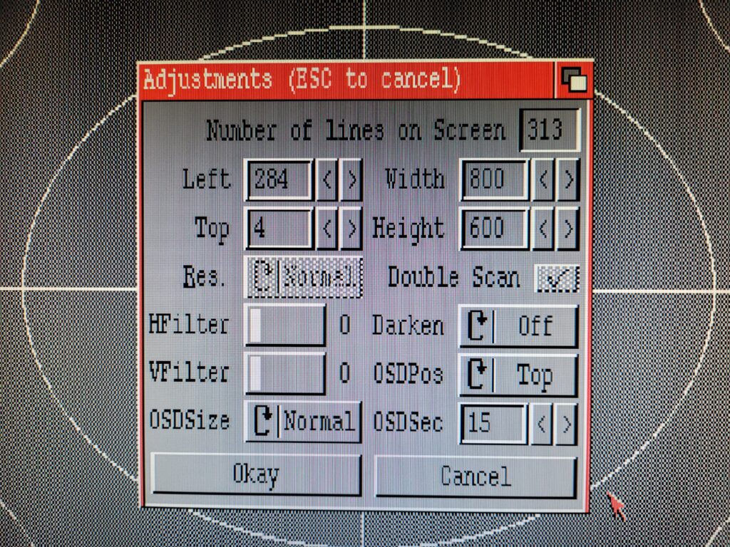
Many interesting settings are hidden away in the ‘Test/Adjust’ section, not least of which is the ‘Darken’ option. This basically emulates the scanlines of a CRT monitor on your modern flat screen monitor. Settings range from 6% to 75% depending on how strong you want the effect. It only works on Double-scan modes and defaults to being switched off. There are also several settings for the On-Screen Display so you can tweak the size, length of time it is displayed and also which corner it appears in. Of course you can also adjust the size and position of each Indivision display mode from here too.
Summing Up
This is a terrific device for anyone who enjoys using the Amiga 1200 as a hobby machine and wants to get the best possible image from it. The Indivision AGA Mk3 definitely allows one to maximise the power of the AGA chipset by allowing it to display resolutions that would never have been possible before. It also allows hassle free connection to modern LCD monitors and TV’s via both HDMI and VGA which is another huge benefit.
Of course that’s not to say it isn’t great for gaming as well because it is. However if all you want to do is play games then I’d consider this to be overkill and there are much cheaper options available. It also requires a certain degree of… experimentation which the average gamer may find off-putting.
Short of getting an actual RTG card for the Amiga this is as good as it gets and when utilising HDMI the picture quality is simply stunning. Considering this is still using the A1200’s native AGA chipset to deliver the image it’s a really impressive sight to behold.
In short; if you have the funds, want to push your A1200 graphics to the limit and enjoy tinkering then I highly recommend this device.
Discover more from Lyonsden Blog
Subscribe to get the latest posts sent to your email.

If one likes hdmi connector hanging outside the case then ok, but there is no backplate for HDMI unlike for MK2 models DVI. Also connecting board where HDMI is to amiga with only one screw leaves it moving around (=no good) and it’s too much inside the case too. I didnt mess with any settings too much, because my unit was broken, and later they increase the price lol.
Sounds like your unfortunate experience has tainted your views of the card a little? Sure it’s by no means perfect but it’s a small technical marvel and lets face it, unless you want to fit your A1200 into a desktop PC (or mess with a Raspberry Pi) case there aren’t really any other options.
As for the lack of a dedicated backplate – there are 3D printed backplates available online if you don’t like the supplied fittings.
Hi Steven
I can recommend this guide
https://lesdocs.fr/parametrage-de-lindivision-aga-mk3/
It’s not mine but I’ve followed it and now I have a perfect 1:1 on my 16:9 tv 😉 The guide is in French language but you can switch to English from drop down menu on the right side of this site 😉
Oh, I forgot. At the end of the guide you can find the autor’s configuration file and use it by adding your tv/monitor resolutions to it.
Thanks for the link, I’ll definitely take a look at that! 🙂