Although my VIC20 is working perfectly I thought it would be prudent to take some precautions to help it continue to lead a long life. I’ve read about chips failing in the VIC, often due to excessive heat build-up. To this end I set about checking just how hot the various chips were getting and see if I could find a way of cooling my VIC20.
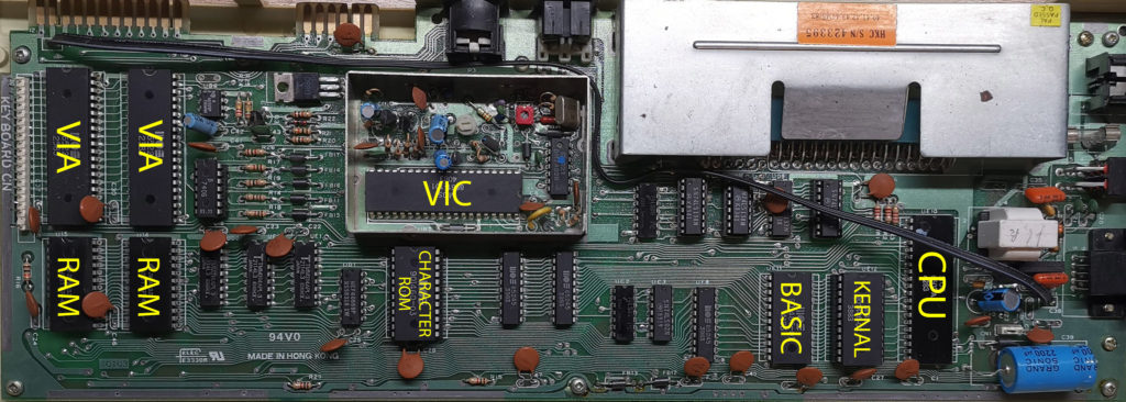
Here’s a diagram I knocked up identifying the main chips on my VIC20 motherboard. I made it for my own future reference but it may be helpful to others too.
The first thing I did was leave my VIC20 running a game for a couple of hours. I chose GORF as it continually runs in ‘attract mode’ which I hoped would give everything a good workout. I let this run for 2 hours before lifting the lid and checking the chip temperatures.
To perform the testing I used a cheap infrared thermometer that I picked up off Amazon. With this gadget I could simply point the laser at a chip to instantly read its temperature. I found that different areas on the same chip could give significantly different temperatures. The difference was often as much as 5C so I noted down the highest temperature measured for each chip.
Chip Temperatures
Perhaps not surprisingly the hottest chip on the board was the VIC running at 46C . The next hottest were the 2 VIA chips at operating at 40C. Running in joint third place was the Character ROM, BASIC, Kernal and CPU chips at 35C each. Last place and probably of little concern were the two large RAM chips in the bottom left which reached 30C. The rest of the chips were all below 30C so I felt these didn’t warrant any further attention.
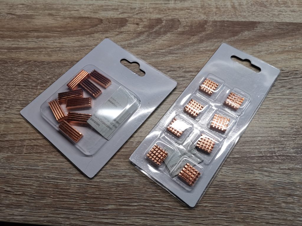
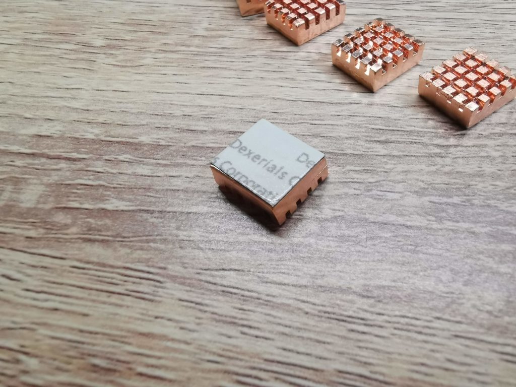
I didn’t want to install a fan in my VIC20 so I decided on heatsinks to help cool things down. Because all the chips are different sizes a ‘one size fits all’ approach wasn’t going to work. To this end I took a few measurements and went looking for something suitable. In the end I settled on these copper heatsinks from Amazon and picked up 3 packs in total. I had already bought a pack of these in case any of the smaller chips needed cooling too.
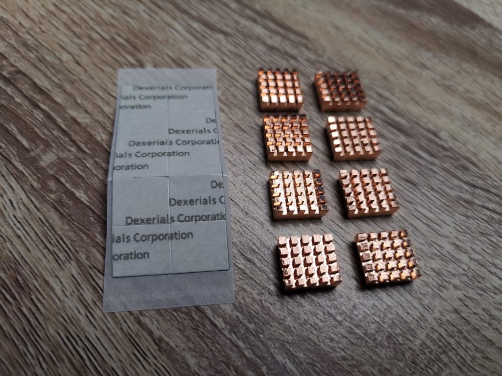
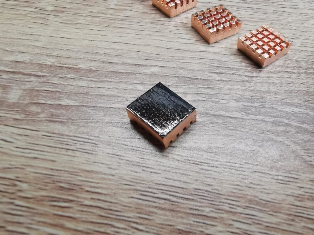
Although they look square, they’re aren’t quite as they measure 10mm x 11mm. However they are the perfect size to both fit the width of each of the main chips and to be used in multiples to maximise surface coverage on the various chip lengths. They also came supplied with self-adhesive thermal tape which allowed easy installation.
Preparation
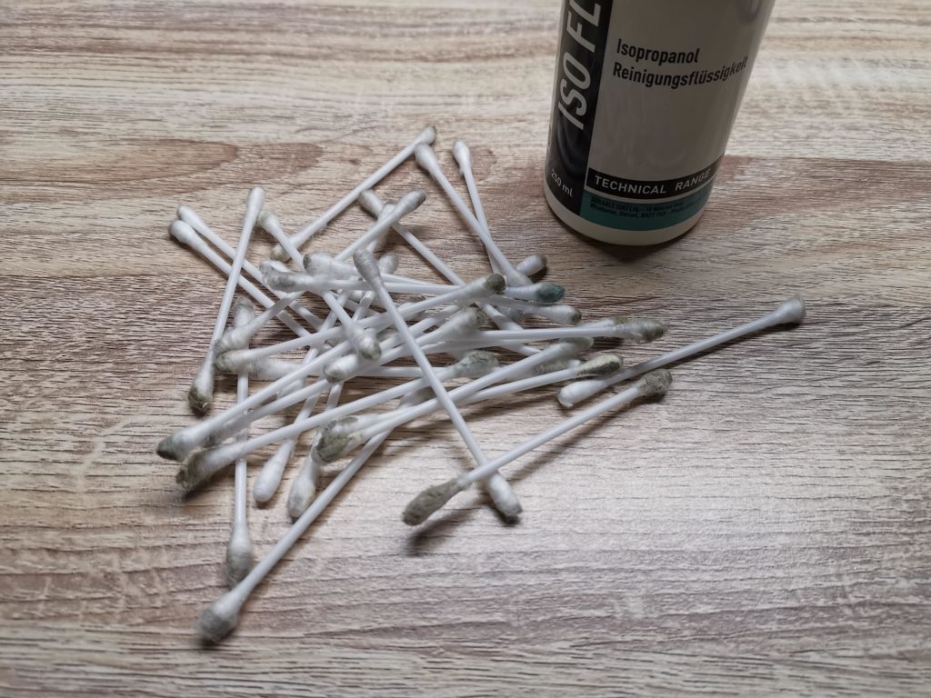
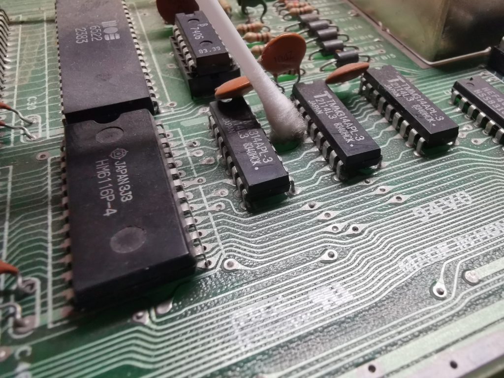
Before even thinking of installing the heatsinks I needed to do some cleaning. The chip surfaces needed to be squeaky clean to ensure good adhesion of the thermal tape. Also, besides a few blasts of compressed air I hadn’t got around to cleaning the motherboard since I rescued my VIC20 from the attic. A bottle of Isopropyl alchohol and a box of Lidl’s finest (i.e. cheap) cotton buds was the order of the day here.
All I did was gently wipe the surface of every chip, component, contact and the surface of the board itself until the cotton buds came up clean. Of course if the board was already clean I would have simply cleaned the surface of the main chips and stopped there. The whole cleaning process probably took about half an hour, maybe a bit more but i found it quite therapeutic. I also cleaned the base of the heatsinks just to be sure they were squeaky clean.
The next task was to carefully attach the thermal tape to the heatsinks. I simply peeled one square off the sheet and carefully aligned it with the edge of a heatink before pressing it firmly into place. It was important to get these aligned correctly otherwise it would have made placing them next to each other very difficult.
Once I was ready to attach a heatsink (I’d already loose-fitted them to check the best way to arrange them) I just needed to peel the protective film off the thermal tape. I found a sharp blade was very useful here if I couldn’t catch the edge of the plastic film with my fingernail.
Installation
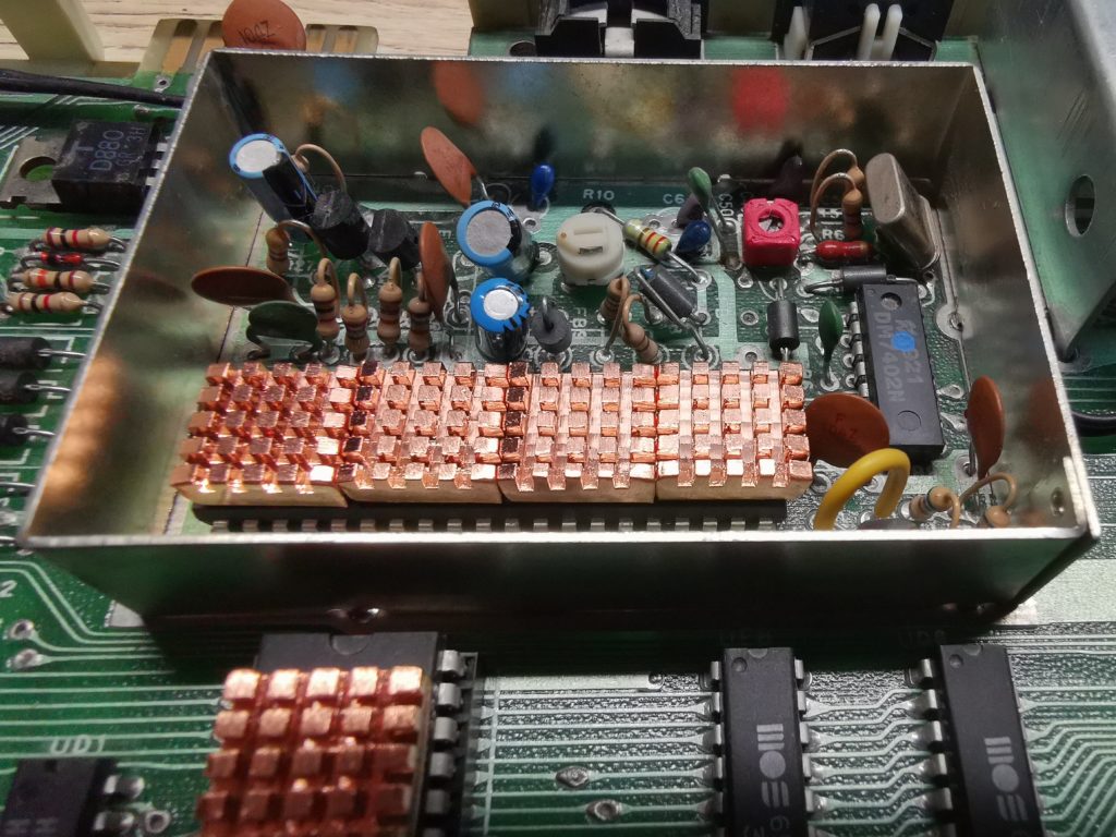
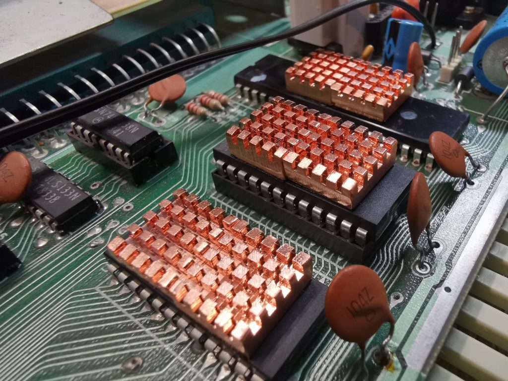
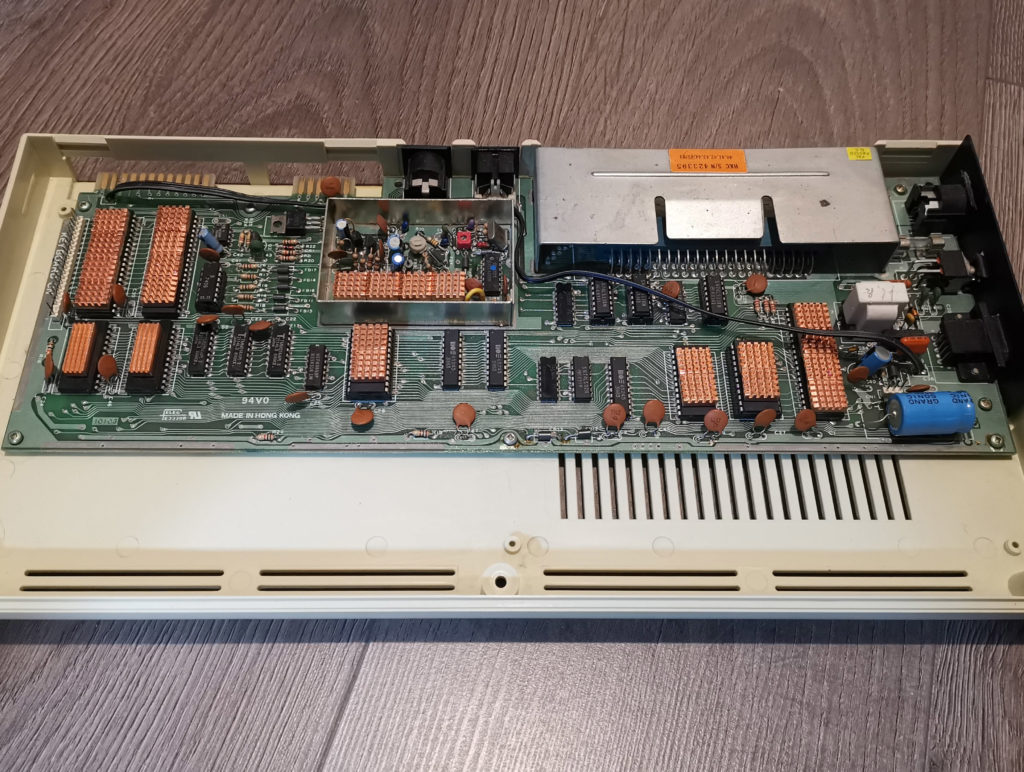
This was the best part, sticking the heatsinks onto the chips. For the bigger chips like the VIA, VIC and CPU I used 4 heatsinks butted up close to each other. For most of the other chips like the RAM, BASIC and Kernal I just used 2. By this stage I ran out of the ‘not quite square’ heatsinks. Because of this I used 2 of the tall slim heatsinks to top off both of the RAM chips. These were only reaching 30C anyway so didn’t need serious cooling.
I found the thermal tape stuck the heatsinks down really well which made it all the more important to position them correctly first time. Moving them around after they’d been stuck down was almost impossible.
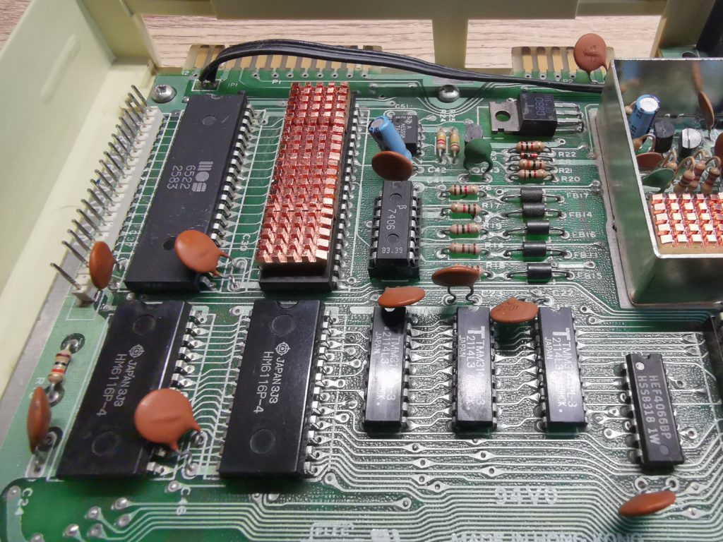
First VIA chip done… that ceramic capacitor bent over the lower part of the left VIA chip needed to be carefully bent away before heatsinks could be fitted
Did it actually do anything?
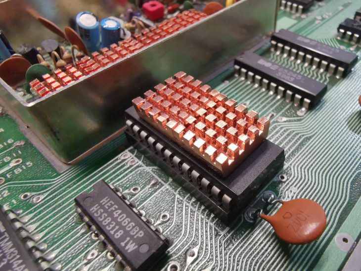
Here’s a photo of the completed project with all the main chips covered by heatsinks. It certainly looks the part now but did the addition of the heatsinks actually have any appreciable impact on cooling my VIC20?
In order to see if the project actually made any sort of meaningful impact I repeated the same test as before. I popped the lid back on, slid GORF into the cartridge slot and let my VIC simmer for 2 hours. I measured temperatures in the same way as before, noting the highest recorded reading for each one.
I’m happy to say I found that the heatsinks did actually result in a decent improvement in temperatures across the board. The biggest improvement came from the VIC chip which went from hovering around 46C down to 38C, a drop of 8C which is fantastic. The VIA chips fell from 40C to 35C and the VIC Character ROM from 35C to 31C. The remaining chips showed drops of between 2-3C which whilst not as impressive is still an improvement.
I’m not really sure why the different chips exhibited different levels of improvement but nevertheless I’m very happy with the results. My VIC20 is almost 40 years old now and I’m hoping this little project helps it last a good few more!
Discover more from Lyonsden Blog
Subscribe to get the latest posts sent to your email.

Hello, I am from Iran and I had a question for you. I have a Commodore vic20. When I turn it on, it does not show any image on the TV and the screen is black. I am sure that the cable is healthy. I opened the device, cleaned all the sockets, and it does not even have cold dead solder. Do you know where the problem comes from?
How are you connecting the VIC20 to your display device? If you are using an RF modulator then try getting hold of a proper VIC20 video cable that can connect direct to a monitor via composite video. If you are already using such a cable – do you have another than you can swap to check it’s not the cable? A faulty PSU could also cause this – the old C= PSU’s are notorious for failing. A working one should output both 5V and 9V volts. Check online for the pin-outs and test it with a multi-meter. Alternatively the VIC chip itself could be faulty – this is the main chip that handles the VIC20’s graphics (and sound!). If you are lucky it will be socketed and you can easily swap it for another… otherwise you would need to desolder it first. Hope that’s given you some ideas to try and good luck!
Great post, really useful, thanks! Recently bought an untested (non CR) Vic from eBay: turns out all garbled chars on screen at boot. Was able to find it was due to a single bad ram chip.
Replaced and everything works. Today also did full recap and, thanks to your info, will add heat sinks.
Glad you found it useful Stefan. That reminds me – I need recap my own Vic. Will get around to it one day!
Interesting post, thanks. Wondering if it was necessary to use quite so many heatsinks, as some chips seem to have hot spots in use?
Possibly not but the heatsinks were pretty inexpensive so no need to be frugal with them! 🙂