Lyonsden Blog

Category - PET

Checkmate Retro Monitor

A couple of years ago I backed a Kickstarter campaign for a new ‘Retro Styled Modular IPS Display for old and new systems” (from now on I’ll just refer to it as the ‘Checkmate Retro Monitor’). It was basically a brand new monitor using a modern IPS display that incorporated a ton of ‘old’ inputs for hooking up all the retro game consoles and computers we know and love.

I’ve been following the project closely over the past two years, tuning in to Steve Jones’s regular YouTube updates documenting it’s progress, revisions and refinements along the way. However the wait is finally over now and my shiny new Checkmate Retro Monitor is in my possession courtesy of DHL.
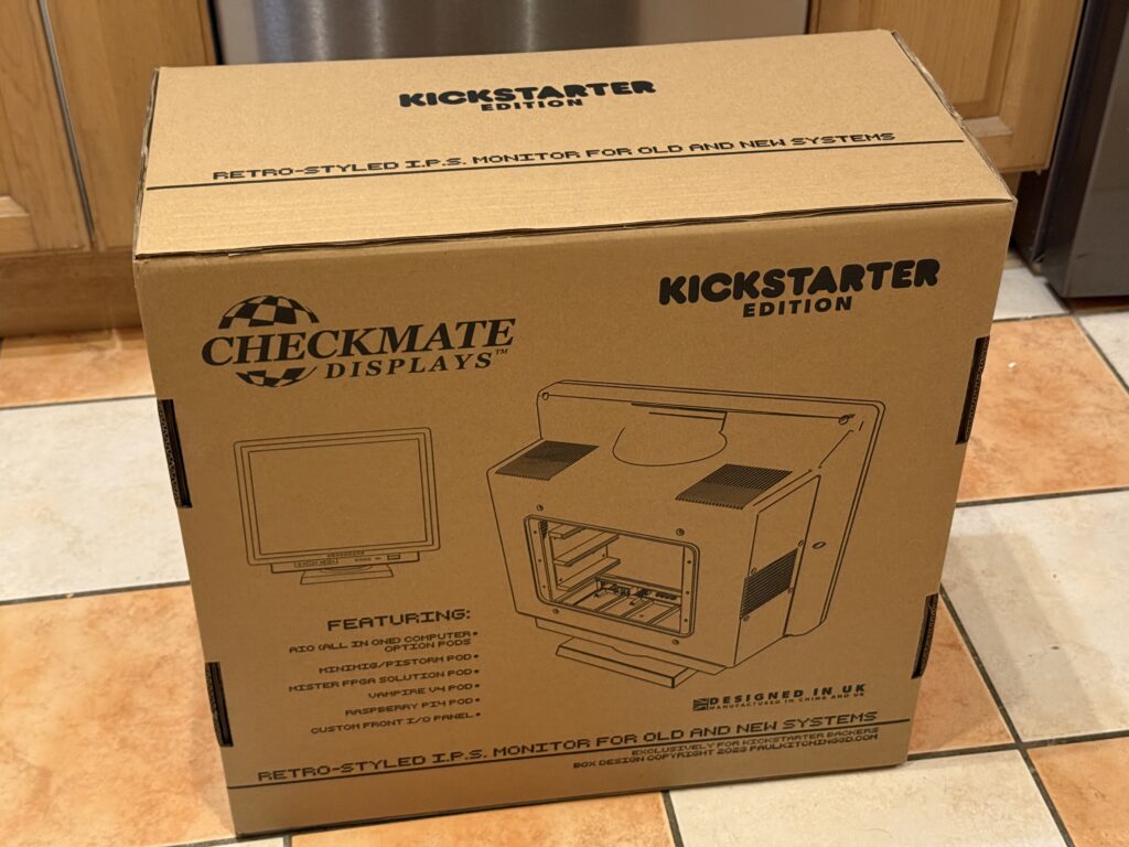
 

Checkmate Retro Monitor

Monitor Box


It came double-boxed which ensured it arrived in tip top condition with the inner box not suffering any damage at all
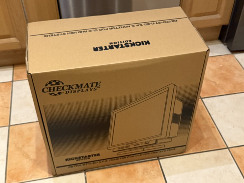
 

Checkmate Retro Monitor

Checkmate Retro Styled Monitor Box


The monitor itself is protected by heavy duty polystyrene, further protecting it from damage.
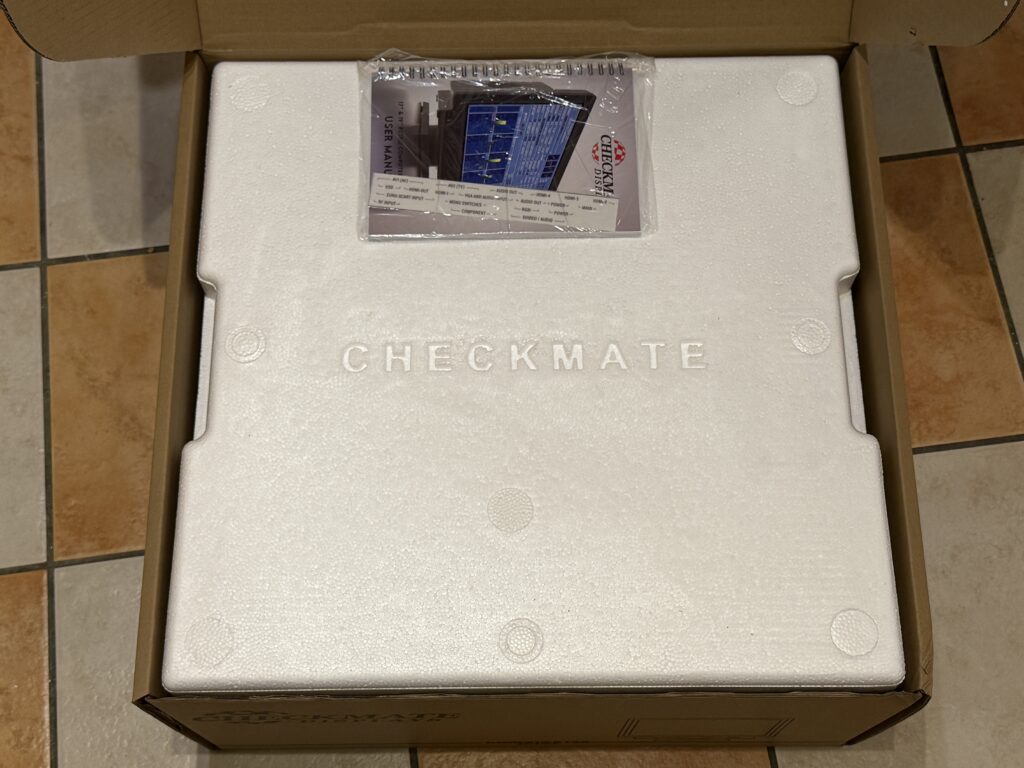
 

Checkmate Retro Monitor Manual

Colour manual tucked into packaging


A little recessed area houses the spiral bound full colour manual.
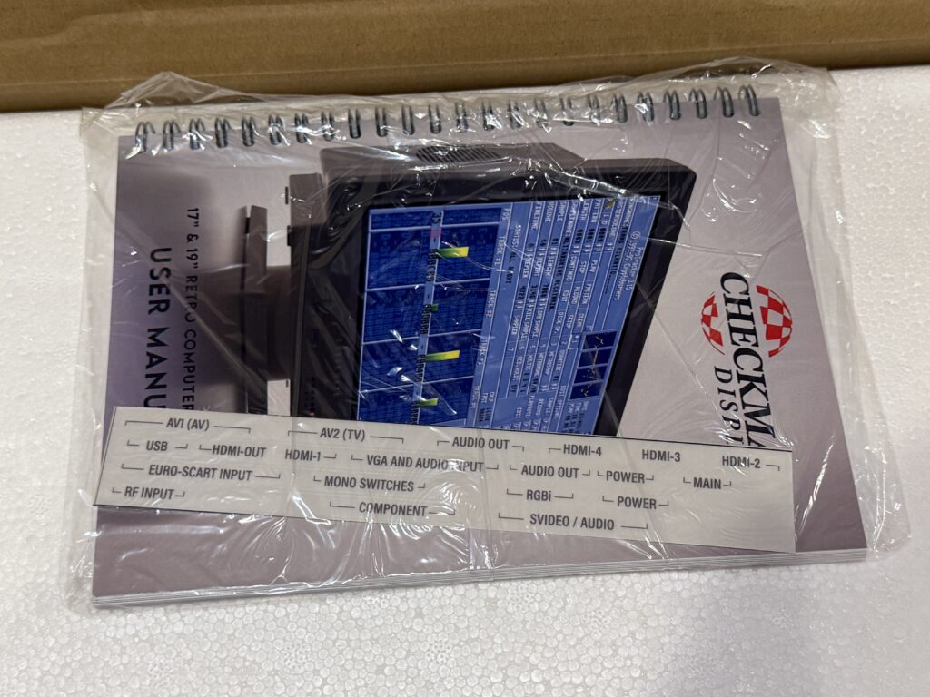
 

Checkmate Monitor Manual


After removing the top half of the polystyrene packaging the monitor is finally revealed. In true retro fashion, even though I ordered the white version (the alternative was black) it is actually beige. This is a good thing as I don’t own a single ‘white’ retro computer – they have all yellowed to some degree or other, even after retro-brighting.
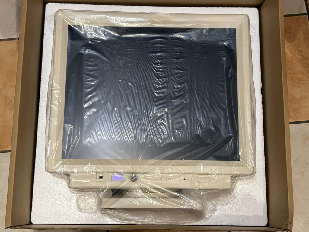
 

Checkmate Retro Monitor

First glimpse of my new monitor


The packaging was hiding a few more things out of sight…
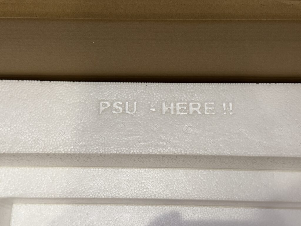
 

Just as well I didn’t toss the packaging straight in the bin!


…inside another box tightly wedged into a recess in the polystyrene.
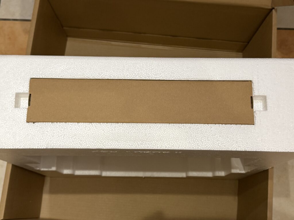
 

Accessories box


This contained the remote control, PSU for the monitor and a couple of alternative panels for the bottom front panel of the monitor.
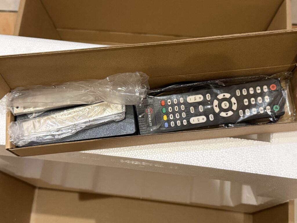
 

Accessories


There were a couple of noticeable omissions here, namely a set of batteries for the remote and an IEC (kettle) cable. We (the Kickstarter backers) were told not to expect these so this came as no surprise. I’m sure most people will have these things in plentiful supply if they’re anything like me.


Back Panel

The back panel is where all the magic begins and is where you can add and remove the ‘pods’ that give the monitor its unparalleled versatility,
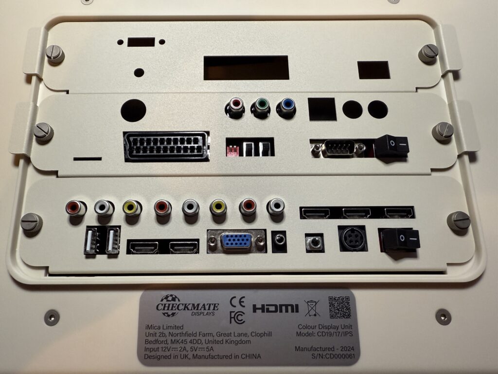
 

Checkmate Retro Monitor

Ports galore


Out of the box none of the ports are labelled – this is a little DIY job for the user!
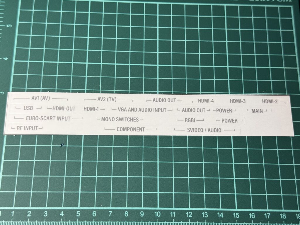
 

Sticker Sheet


Tucked inside the manual is a small sheet of stickers which need to be aligned correctly and stuck to the relevant areas on the back to identify each group of connections.
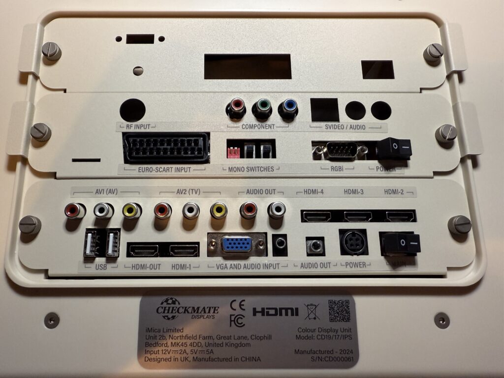
 

Labelled ports.


I used a pair of tweezers to carefully position the stickers followed by a blast from my heat gun to ensure they were firmly attached.


Pods

All the monitors come with the bottom ‘Pod 0’ which leaves two bays to fill. I opted for (Appy’s) Retro Scaler with GBS Control and a Raspberry Pi pod. I could also have chosen a MiSTer Pod but I already own a few Raspberry Pi’s so that was the more appealing option. I do hope to pick up a MiSTer at some point in the future, funds permitting, but for now I’m looking forward to setting up either PiMiga or AmiKit on a Pi 4 housed inside my monitor!
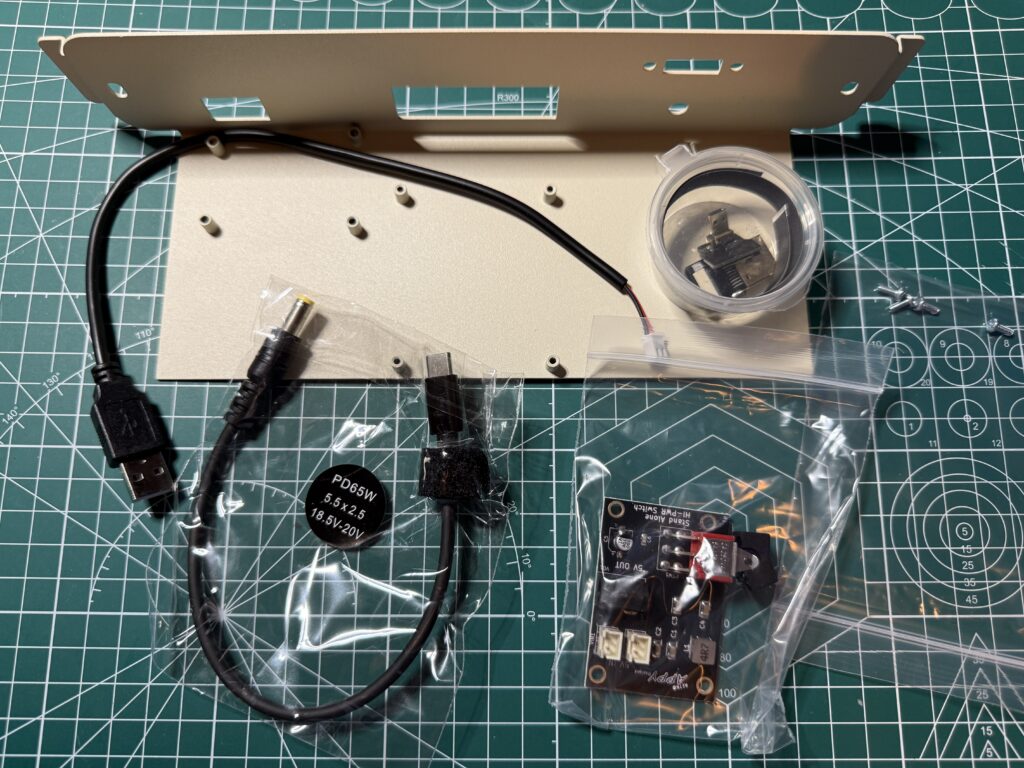
 

Contents of the Raspberry Pi Pod Kit


The monitor includes a fully functioning tilt and swivel base, stereo speakers, an OLED display panel on the front, a remote control and of course more inputs around the back than you can shake a stick at.


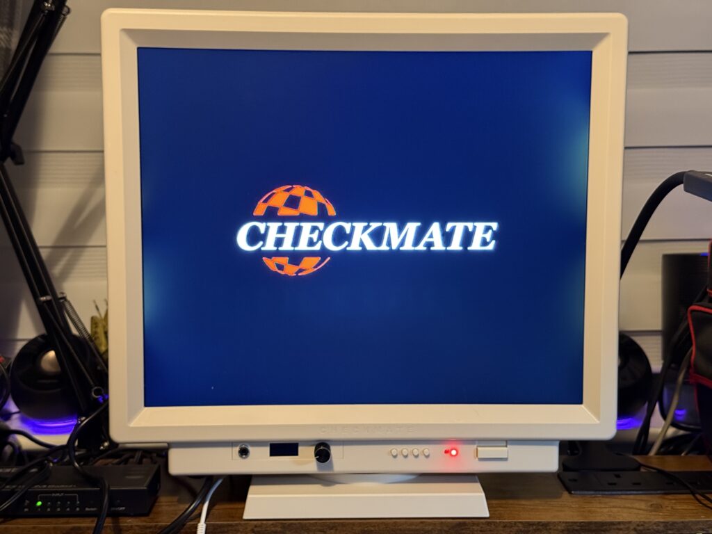
Powering On my Checkmate Retro Monitor for the first time
 

Checkmate Retro Monitor

Screen with light bleed


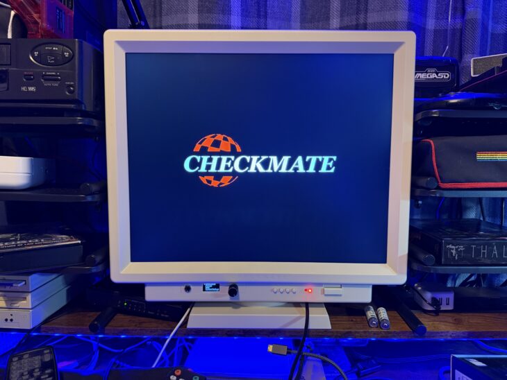
The monitor powered on without issue and displayed a very natty ‘Checkmate’ logo. However I was a little bit disappointed to see quite a lot of backlight bleed down both sides of the screen which is definitely something I wasn’t expecting. I put up with it for a week or so before deciding to tinker with the bezel screws and managed to greatly reduce the issue thankfully.
 

Checkmate Retro Monitor

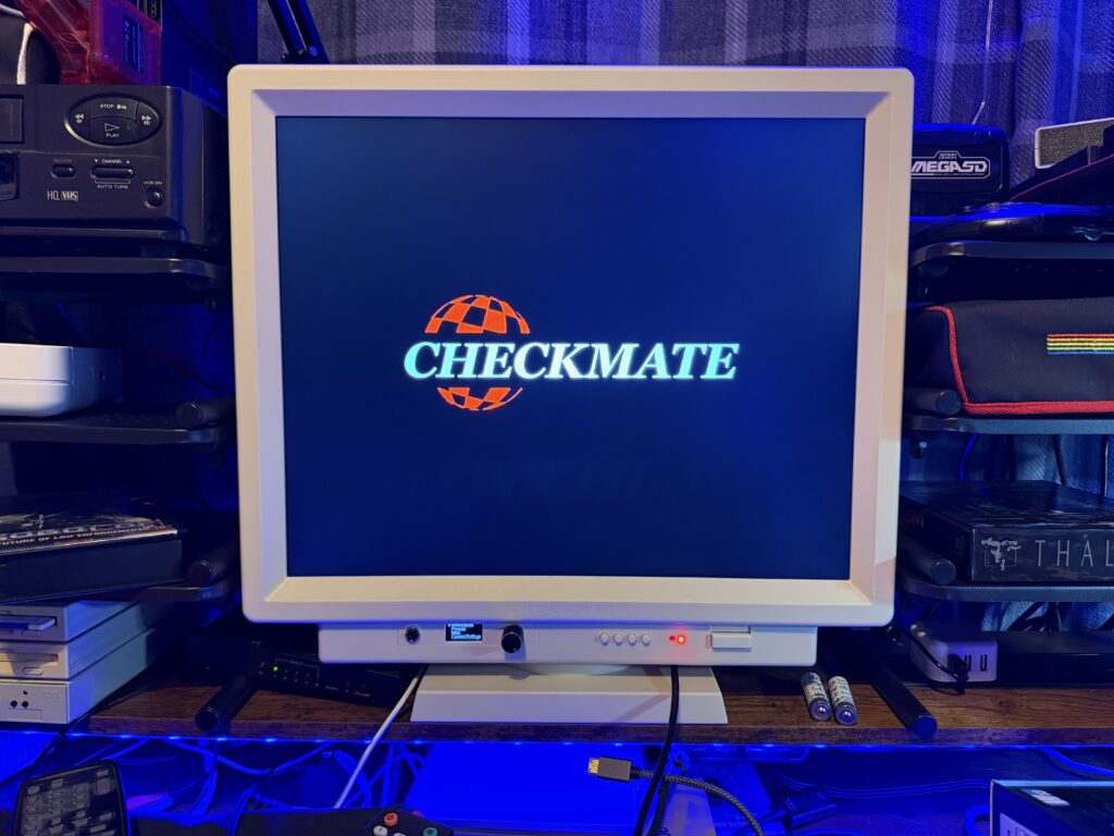
Screen without the light bleed issues


I basically had to slacken the side bezel screws off almost to the point were they came out completely but this did pretty much eradicate the bleed as you can see in the photo above (taken a week later after I had rearranged my desk). The bezel is a little loose both sides now but it’s not going anywhere (there’s other screws holding it in place) so it doesn’t bother me too much.
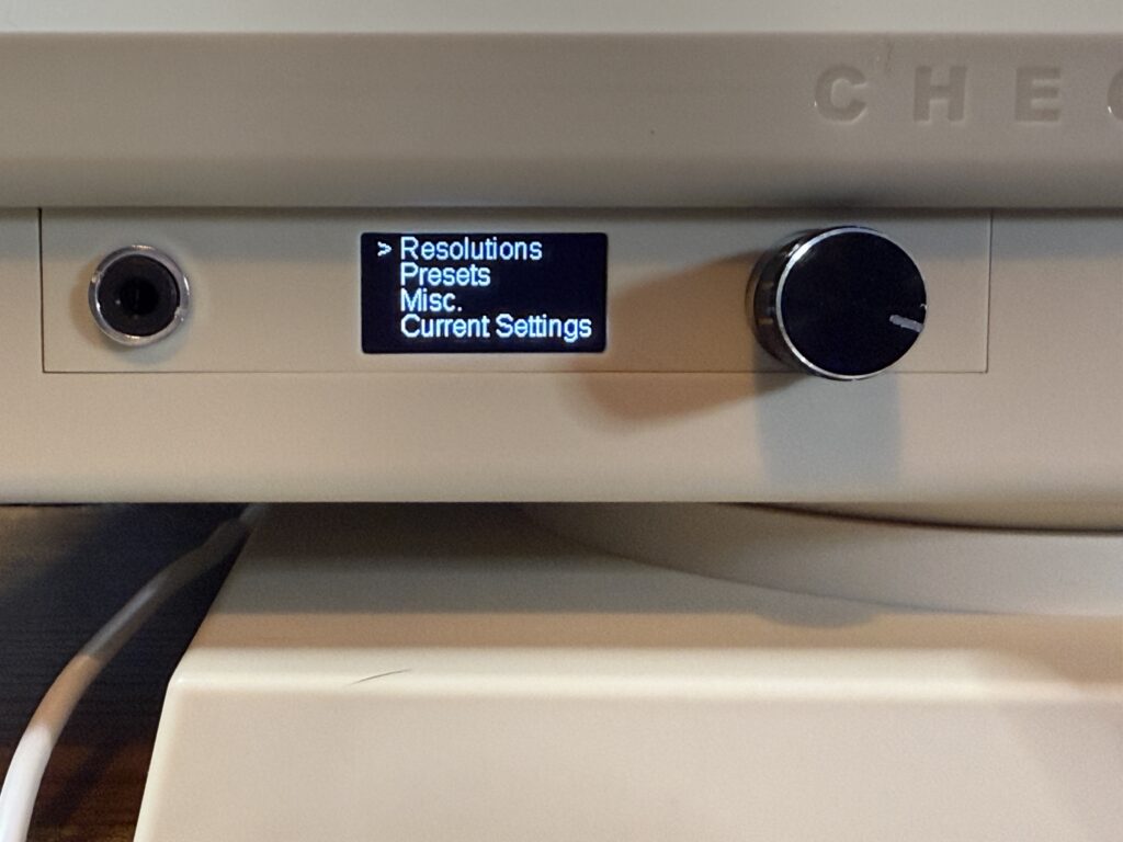
 

OLED Screen for the GBS Controls


Underneath the screen is a tiny little OLED panel that provides access to some of the GBS Control features/pre-sets on the Scaler via the jog dial. You can use it to check what the current settings are and also reset the scaler without having to power it off and on again. Changing pre-sets (stored custom configurations) is as simple as selecting a numbered pre-set from the menu and pressing in the jog dial.


Hooking up stuff to my new Checkmate Retro Monitor
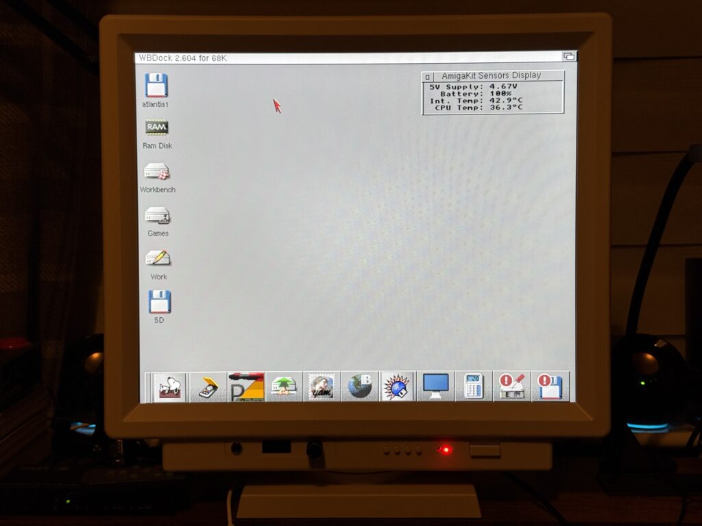
 

Checkmate Retro Monitor

Amiga Workbench via HDMI


My Amiga 1200 is fitted with an Indivision AGA Mk3 board so I was able to hook this up to the Checkmate Retro Monitor directly via HDMI. After a (good) few minutes playing around with the Indivision config tool (and some pointers off a helpful soul on the discord channel) I was able to achieve a beautifully crisp, rock-steady Workbench display running at 1280×1024 resolution that filled the screen from edge to edge.
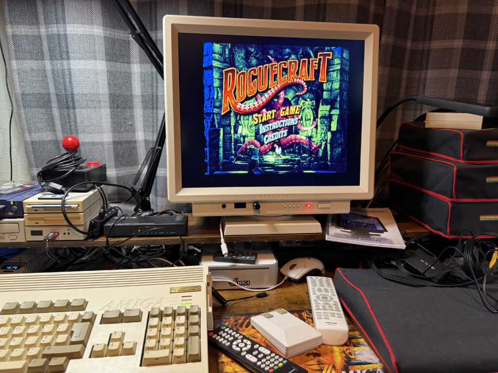
 

Checkmate Retro Monitor

Roguecraft running on my new Checkmate monitor


This also gave me a good excuse to boot up Roguecraft for a quick blast which displayed just fine straight out of the box. Such a great game too – I don’t need much of an excuse to fire it up!

After a few goes of Roguecraft I decided it was time to hook up a few different systems to the monitor to see how it performed with those.
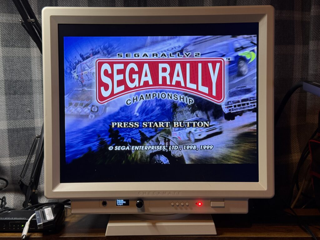
 

Checkmate Retro Monitor

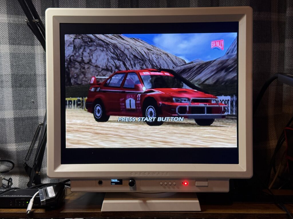
Sega Rally on Dreamcast via Composite cable


I tried my Dreamcast first and hooked it up via a Composite cable and got a really nice picture.
 

Checkmate Retro Monitor

Sega Rally on Dreamcast via Composite cable


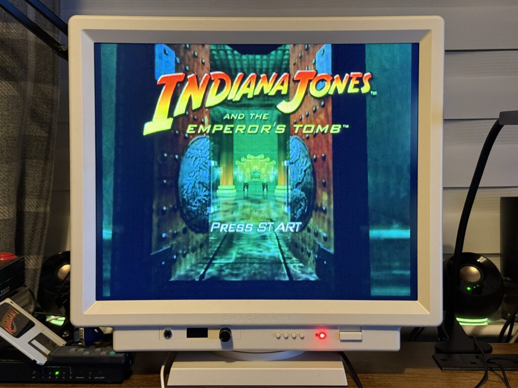
Next up I hooked up my OG Xbox and had a blast of Indiana Jones and the Emperor’s Tomb. This was hooked up via an HDMI adapter cable and I had no issues with picture quality.
 

Checkmate Retro Monitor

Indiana Jones on Xbox via Composite to HDMI adapter


I fired up my trusty Commodore 64C next with an (admittedly cheap) composite cable and got a pretty decent looking picture. It was a little soft but perfectly useable. There were some very very faint vertical lines but I’m sure I could eradicate those if I spent some time twiddling with the pots on my LumaFix64 board.
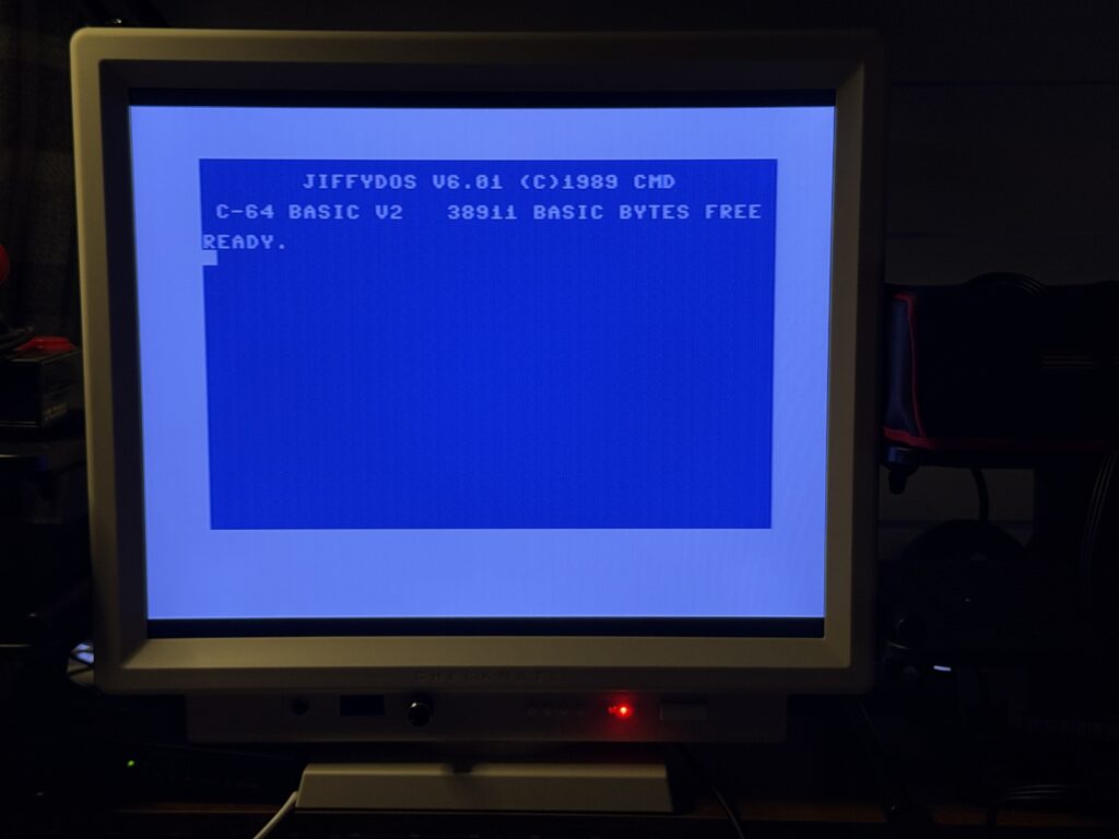
 

Commodore 64 via Composite cable


SCART Test

I thought I’d give the Scaler inputs a test next. I hooked up my pretty ancient Matsui VCR (which used to belong to my Grandad back in the 1990’s) using a SCART cable and popped in a copy of the greatest movie of all time…
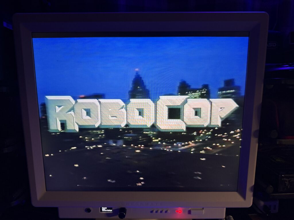
 

I’d buy that for a dollar!


…and then proceeded to spend the next hour and a half watching the whole movie. Picture quality was really good considering the source and sound was great too with some very meaty gunshot and explosion effects coming through the built-in speakers.
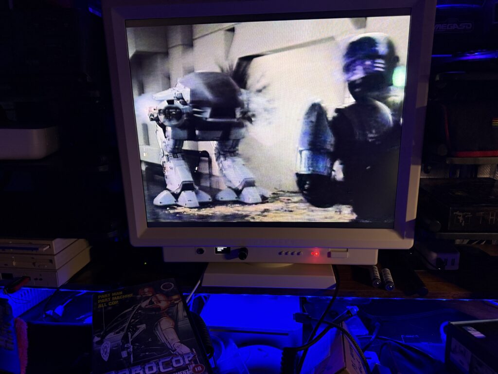
 

Checkmate Retro Monitor

ED209 vs Robocop


It’s probably been 20 years or longer since I’ve watched this with a PAL 5:4 aspect ratio as all my subsequent purchases have been in widescreen. To get this to display I had to select AV3 as the channel but other than that it just worked.
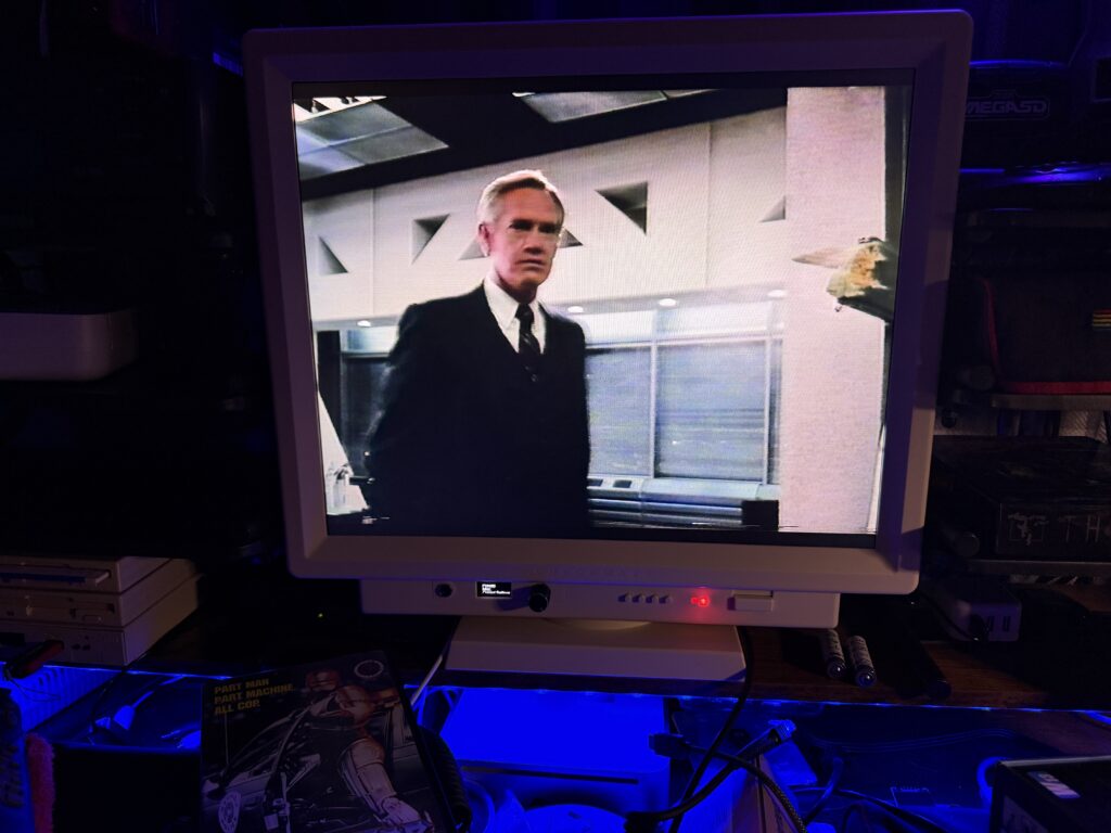
 

Dick Jones really does live up to his name…


Getting an Amiga to display an image via (RGB) SCART proved a little trickier. Initially I just couldn’t get an image at all. After going on the Discord I realised that there are basically multiple ‘hidden’ VGA channels that you can access by pressing the channel up and down buttons on the remote. After doing this a few times (pausing for a few seconds in-between) I eventually got an image to appear. Not very intuitive for sure but at least my monitor wasn’t faulty and now I know! The colours were washed out but I’m putting that down to an issue with my Amiga SCART cable as I’ve had it for donkeys years and not used it for a long time. The colours from my VCR were just fine.
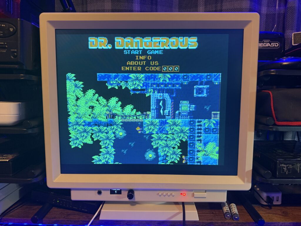
 

Checkmate Retro Monitor

Amiga via RGB SCART (think I need a new SCART cable).


Component Video Test

Thought I’d test out the Component video input next so hooked up my PlayStation 2 slim via Component, making sure to select ‘Y Cb/Pb Cr/Pr’ for Component Video Out in the PS2’s System Configuration. Again I had to jump VGA channels blindly until I stumbled across the correct one. I also needed to spend a bit of time messing around with the settings to get a decent looking, centered image as the default one was over to the far left and was ghosting quite badly. I did get a terrific picture in the end though and made sure I saved my GBS Control settings into a special ‘PS2’ slot which I can easily select from the OLED control on the front panel in future.
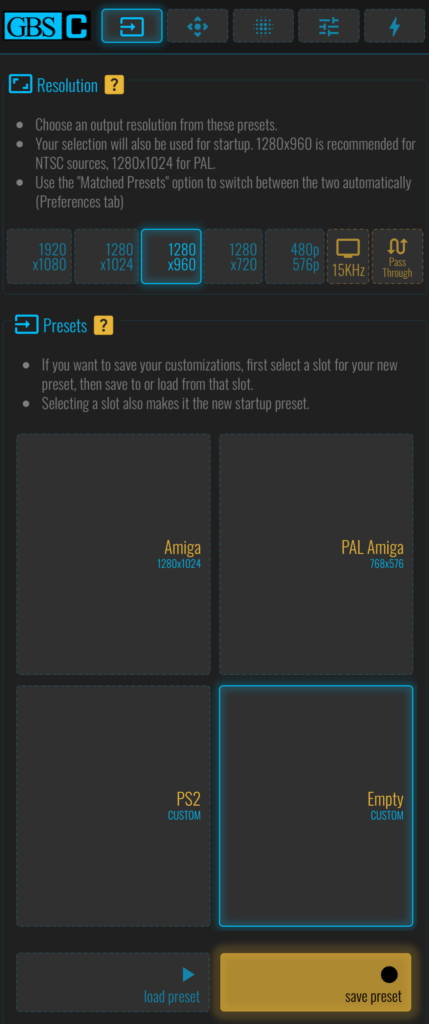
 

GBS Control Interface

Some of my GBS Control Pre-sets – including one for my PS2


Unfortunately there are no red/white RCA stereo inputs which you would normally expect to find with component cables. Thankfully I discovered in the manual that the VGA audio input will accept audio for the component input so by using an RCA to headphone jack converter I was able to get the sound working as well.
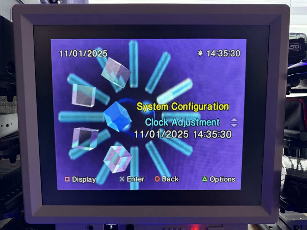
 

Checkmate Retro Monitor

PS2 Config Screen


Playing Media Files via USB Ports

Not really Retro related but there’s a couple of USB ports on the back so I thought I’d give them a quick try and see what sort of media files I could access through them.
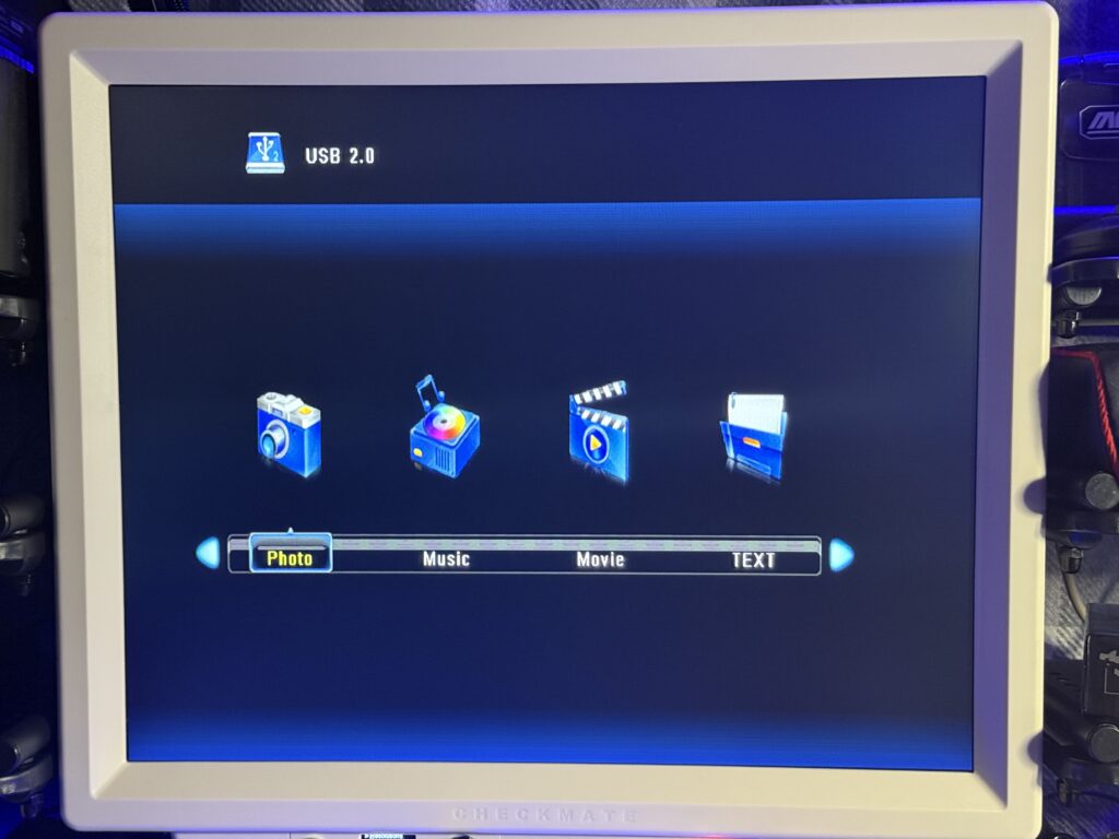
 

USB Media Access Screen


Turns out quite a lot! I put a bunch of music, photos and videos on a USB flash drive and popped it in one of the ports. There are two of them and you have to select the correct one from the on-screen menu via the remote.
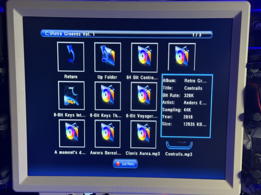
 

Checkmate Retro Monitor

Audio Player


I had no problems dealing with audio files and was able to play back both high bit-rate MP3’s and FLAC files. You can have it play them sequentially, randomly, utilise playlists and access track info – it’s got quite a lot of functionality for a tacked on feature.
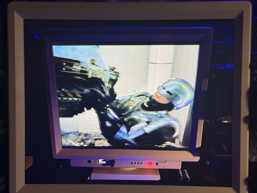
 

Image Viewer


Likewise pictures were no problem at all and the monitor helpfully displays them as a slideshow automatically complete with random transitions.
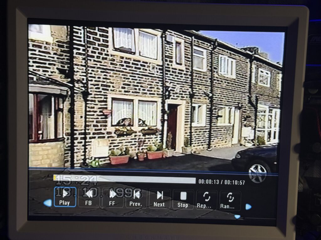
 

Video Player


I didn’t fare quite so well with video playback. It doesn’t like MOV files and although I had better success with MP4 files it is quite fussy about the resolution of them. I was able to play back some (very) old home movie footage in MP4 format successfully though so it’s just a matter of working out the resolutions it likes.

Other Video Devices tested with my Checkmate Retro Monitor

I didn’t bother taking pictures of all the systems I tested out but I can confirm I successfully hooked up all of the systems below without any major issues*.

  • Amiga 500 (via HDMI – Vampire V2)
  • Mega 65 (via HDMI)
  • Spectrum Next (via HDMI)
  • Evercade VS (via HDMI)
  • Analog Mega SG (via HDMI)
  • Mini Pet (via RGB)
  • Mac Mini G4 (via VGA)
  • WiiU (via HDMI).


*I did discover one thing during my testing of the above. If you have anything plugged into the VGA port in slot 0 then you won’t get an image from anything you plug into the scaler (in my case it was my Mac Mini G4). It doesn’t seem to matter if the device you have connected is powered off either. It’s not the end of the world but it is a bit annoying to have to reach around the back and keep plugging/unplugging the VGA cable. I might investigate whether a VGA switch box will solve the issue as it does reference using an ‘isolation switch’ when designing pods that require VGA in the manual to avoid issues.
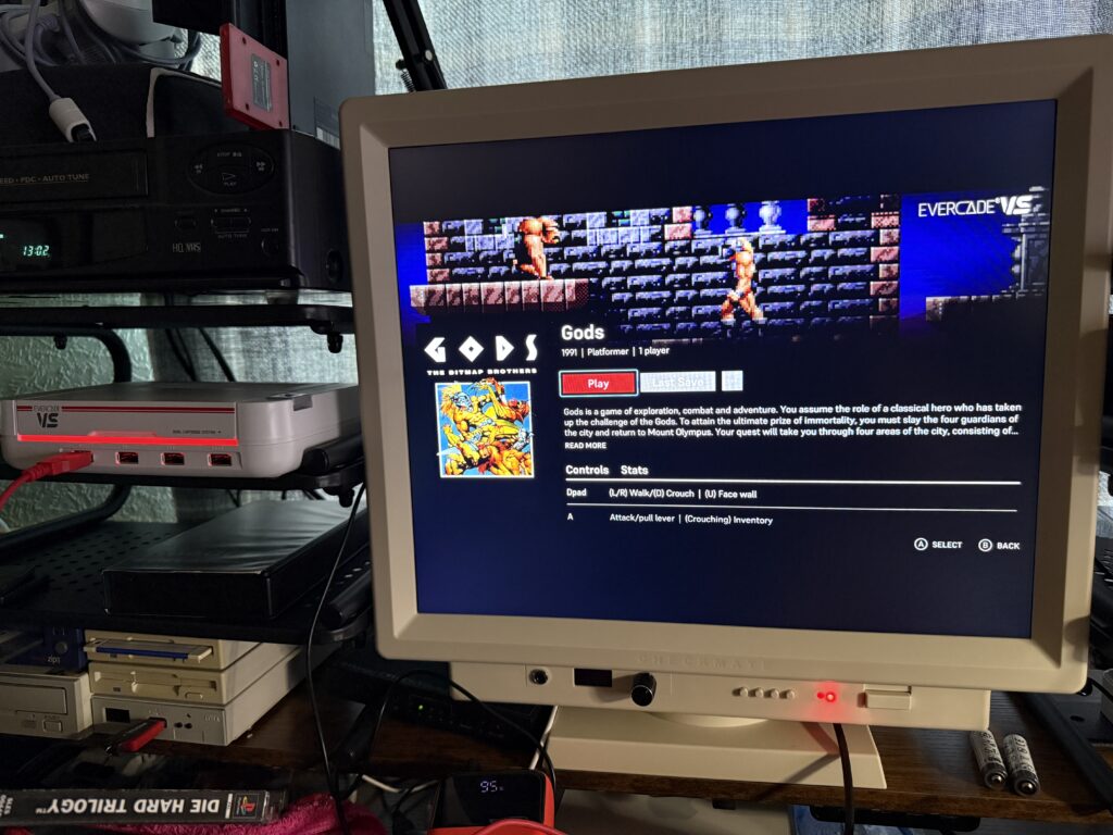
 

Evercade VS

Evercade VS with 16:9 aspect ratio enabled in monitor settings.


Another small thing to bear in mind is that modern stuff, like my Evercade VS console for instance, are designed for Widescreen TV’s and thus produce a vertically stretched image on the Checkmate display. I found that to get the aspect ratio correct I needed to select ’16:9′ in the monitor settings but this came at the expense of chunky black bars top and bottom. This is to be expected though and if it bothers you then it’s probably best to use such systems with modern TV’s and monitors.


Final thoughts about the Checkmate Retro Monitor

This is a great monitor and I’m really glad I bought it. It works amazingly well with all my Commodore machines, especially my Amiga via HDMI. Workbench was never meant to be displayed on a 16:9 display and it’s great to be able to enjoy a lovely, crisp and vibrant image in the original aspect ratio. The quality of sound from the speakers is impressive and the huge variety of input options is a retro collectors dream come true. It does however make me regret not purchasing the extra S-Video/RF expansion and also the HDMI splitter to make use of those unused HDMI ports and the blank holes in the back of the scaler. Steve from Checkmate has said he’ll be offering these for sale separately soon so I’ll be ordering those as soon as they’re available.

It’s not without its drawbacks though and most of those are related to the complexity of using the scaler. There’s frequently an element of ‘fiddling’ required to get something to display on the screen. Once you’ve got an image you often then need to ‘tweak’ it to get it displayed optimally. This is exacerbated by the fact there are actually two ways to adjust the image size; the panel has it’s own built-in adjustment via the VGA menu and then there’s the GBS Control which offers a myriad of customisable features on top of this. It’s quite easy to mess up when adjusting things to the point where you think the monitor is broken so it’s best to make small incremental changes rather than wading in clicking everything in sight! Thankfully you can save GBS Control settings into ‘Presets’ that you can load up in future for each device.

The issue with light bleed (even though I have now sorted it) from the bezel being too tight didn’t create an amazing first impression. The lack of RCA audio inputs for the component cable was also a bit disappointing as most consoles have these connections when you get a component cable, although once more there was a solution which involved purchasing a suitable adapter.

The instruction manual, whilst well made and very interesting, doesn’t really do a great job of actually explaining to a lay person (i.e. someone who wasn’t involved in making the monitor) how to use it. It’s more of a technical reference really. Thankfully there is an active and helpful bunch of people on the Checkmate Discord and Steve himself is quick to respond to issues by email.

This is very much an enthusiast project – a product made by a hardcore retro fan, for other hardcore retro fans. So long as you are happy to tinker, mess around with configurations, menus, twiddle knobs, experiment and learn as you go along then I’m sure you will love the Checkmate Retro Styled Monitor just as much as I do.
Cassette Tape Storage Solution for 2024

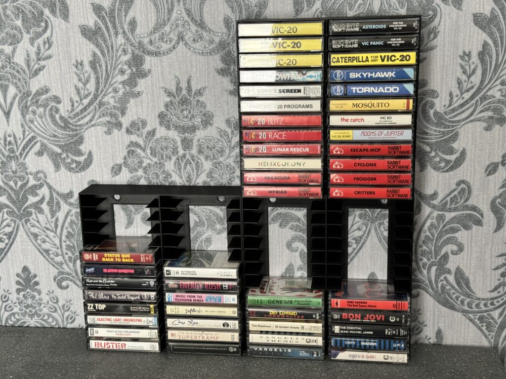
I’ve covered some storage solutions for Cassette tapes in the past but sadly they are no being made. With my own collection of tapes continuing to grow (both music and computer games) I needed a smart, attractive storage solution, and preferably one that would continue to be made for a long time to come.

There was really only one way to guarantee the latter so I’ve ended up designing and 3D printing my own rack and have made it available to purchase on my Etsy Store in case anyone else would like to get one.


Cassette Tape Storage

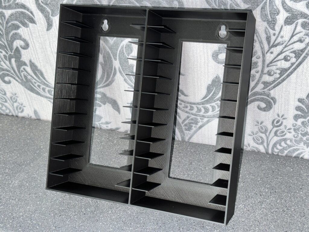
Empty storage rack. Mounting holes at the top.


The finished storage rack measures 23cm x 23cm and is a shade over 5cm deep. I literally cannot make a larger capacity rack as that’s pretty much the maximum size of my printers’ build plates.


This slideshow requires JavaScript.


It has a couple of screw mounting holes at the top so it can be hung on a wall. Alternatively it can be placed free-standing on a shelf, or even on its back inside a drawer.


Cassette Tape Storage

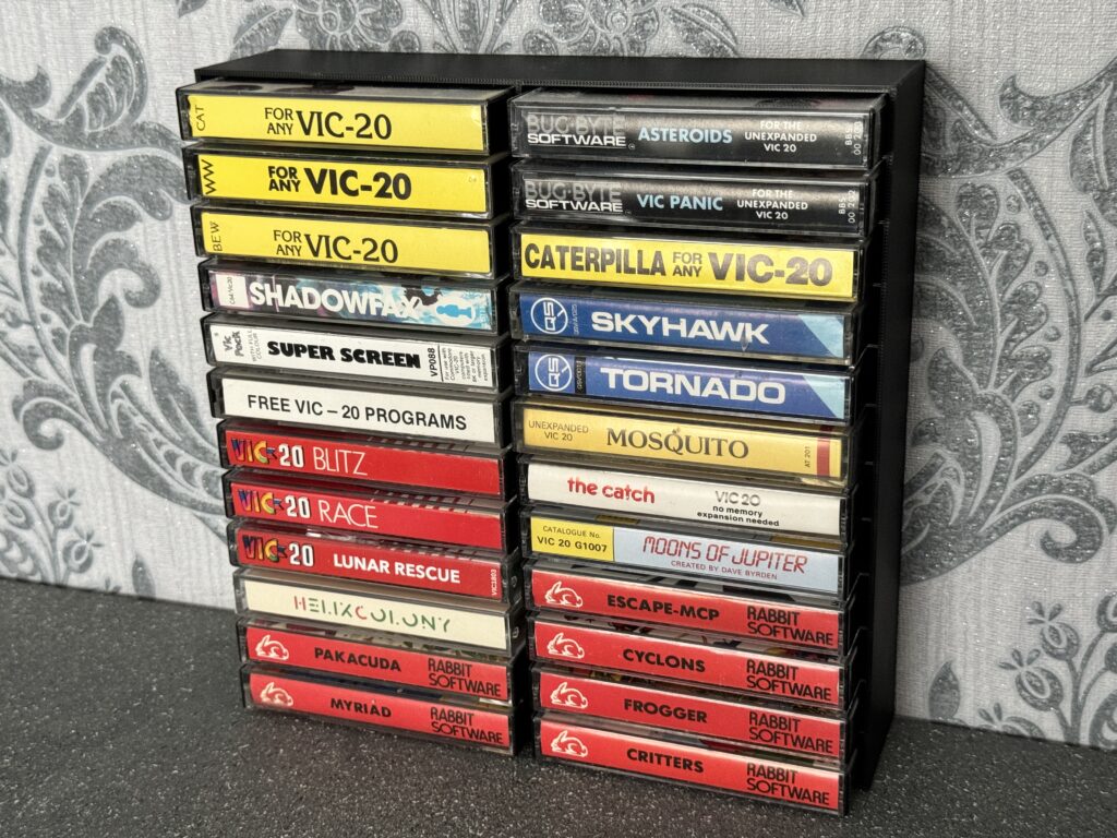
Lots of VIC20 games


The idea is that you can just keep adding more racks as your collection grows.


Cassette Tape Storage

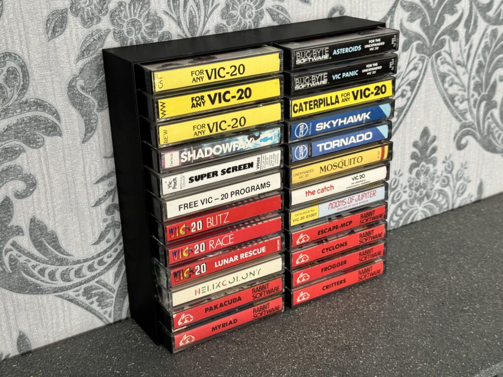
A rack full of VIC20 games.


Although you can just place them side by side or on top of each other when expanding I’d recommend fixing them to the wall if going vertically for stability. Nobody wants their collection of tapes falling on the floor if your cat decides to go mountaineering!


Cassette Tape Storage

Expanding your collection – 3 racks together


These are produced on Bambu Labs printers using premium PLA and each one takes nine hours to complete. They’re really nice quality even if I do so so myself but you can judge for yourself by looking at the photos.

As I said if you want one you can get one from my Etsy store. If you’d like to order more than one then drop me a message and I can sort out a discount.

Building a Mini PET Kit

Mini PET

I’ve long been a fan of those little electronic DIY kits that Maplin used to sell for a few quid. They would have little Xmas trees made up of LED’s, alarm clocks with a handful of digital number displays, that kind of thing. So when I spotted the Mini PET micro-computer kit over at TFW8b I snapped one up straight away. Of course this kit was £350 – a far cry from the inexpensive little packs I used to pick up in Maplin so I was quite nervous about starting the project and messing it up. To reduce the chances of this happening I bought a few inexpensive electronics kits to practice my soldering skills on before letting myself loose on the Mini PET.


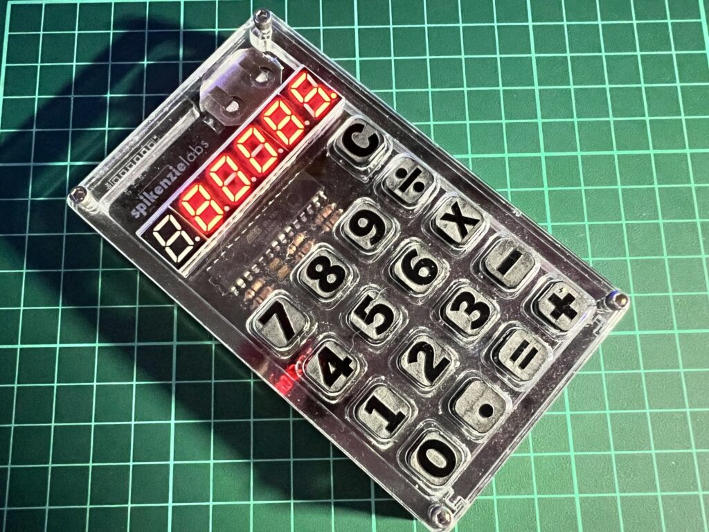
SpikenzieLabs calculator

My completed SpikenzieLabs calculator kit.


Probably the most fun and useful kit was the calculator pictured above that I picked up from SpikenzieLabs. I also picked up a Pinecil soldering iron which I can highly recommend. I paired the Pinecil with some leaded 60/40 solder which I find flows infinitely better than the lead-free stuff so prevalent nowadays. Suffice to say that I procrastinated, researched and practiced quite extensively before I finally felt ready to move on to the main event.


Mini PET

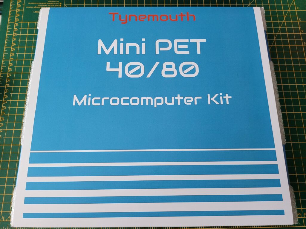
The Mini PET Kit box.


What do you get in the box?

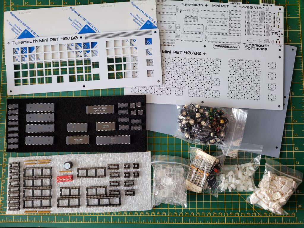
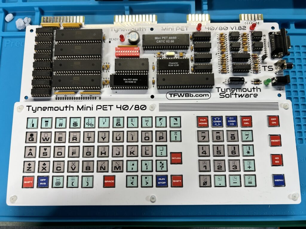
Inside the box you get everything needed to build a fully working ‘Mini PET’ computer including the motherboard, all electronic components, chips, sockets, switches, keys, keycaps and screws. You also get an attractive perspex case complete with stand-offs and screws to build around your completed computer. There’s also a suitable PSU supplied in the box.


Mini PET

Here’s all the Mini PET components included in the box.


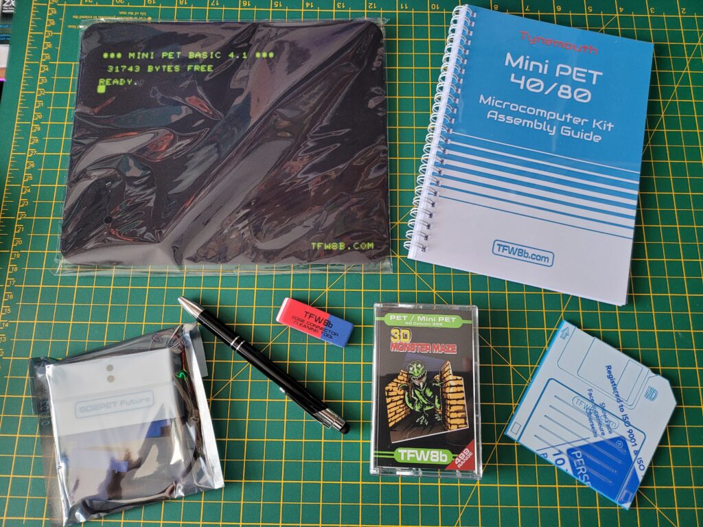
Besides the computer components you also get a comprehensive spiral bound assembly guide and a PET game on cassette; ‘3D Monster Maze’. Also included (as an optional extra) was an SD2PET device which I think is a pretty essential addition. There was also some fun merchandise included too; a fabric mouse mat, a ‘floppy disk’ coaster, a rubber and a snazzy biro/iPad stylus.


Mini PET

The rest of the box contents including the all important manual, SD2PET device and 3D Monster Maze game plus assorted merchandise.


Getting Started

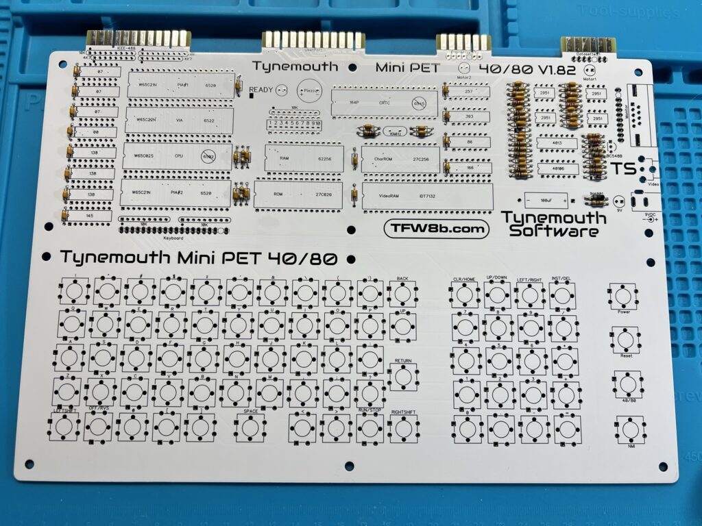
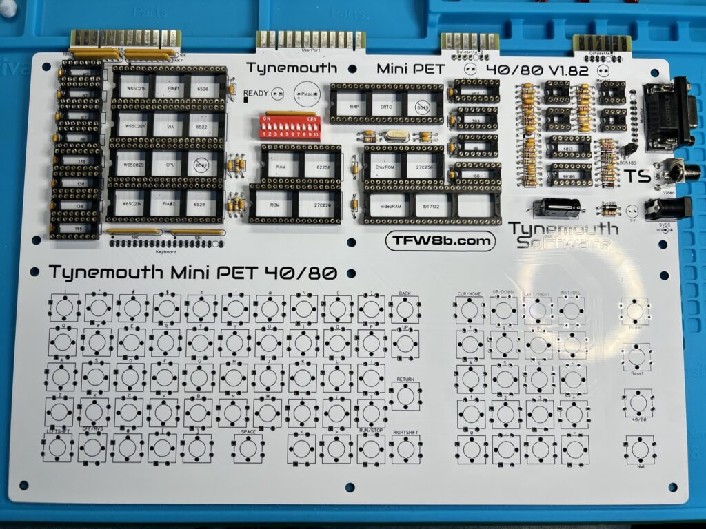
The first stage of building the kit involved fitting all the smaller electronic components to the board, starting with the resistors and capacitors. The instructions helpfully included colour code charts to help identify the correct resisters but I double checked each one with my multi-meter just to be on the safe side.  I found a magnifying glass to be pretty useful here too as some of the coloured bands are pretty small and the writing on the caps was almost invisible to my middle-aged eyes.


Mini PET

The Mini PET mainboard with resistors and caps installed.


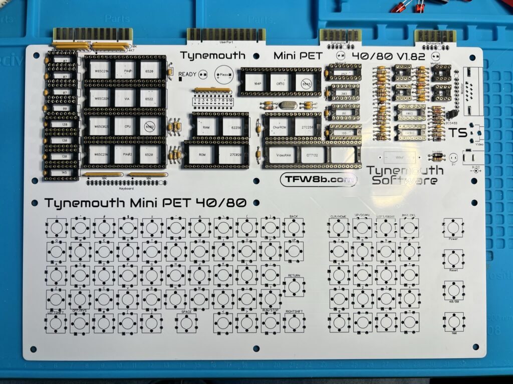
Next up was the fitting of the single timing crystal along with sockets for the chips and the resistor arrays. The sockets were a little tricky to install as I couldn’t bend over their legs like I could with things like resistors. I ended up using lumps of blue-tack to keep them fixed whilst soldering them as I found this worked really well.


Mini PET

The board now with added sockets, timing crystal and resistor arrays.


The DIP switch array, large electrolytic capacitor and the power and video sockets were installed next. The RGB socket in particular needed quite a bit of solder to anchor it into position so I whacked up the temp on my Pinecil temporarily to make this easier. Again blu-tack came to the rescue here to keep them in position whilst the board was upside down.


Mini PET

…with added DIP switch, ports and electrolytic capacitor.


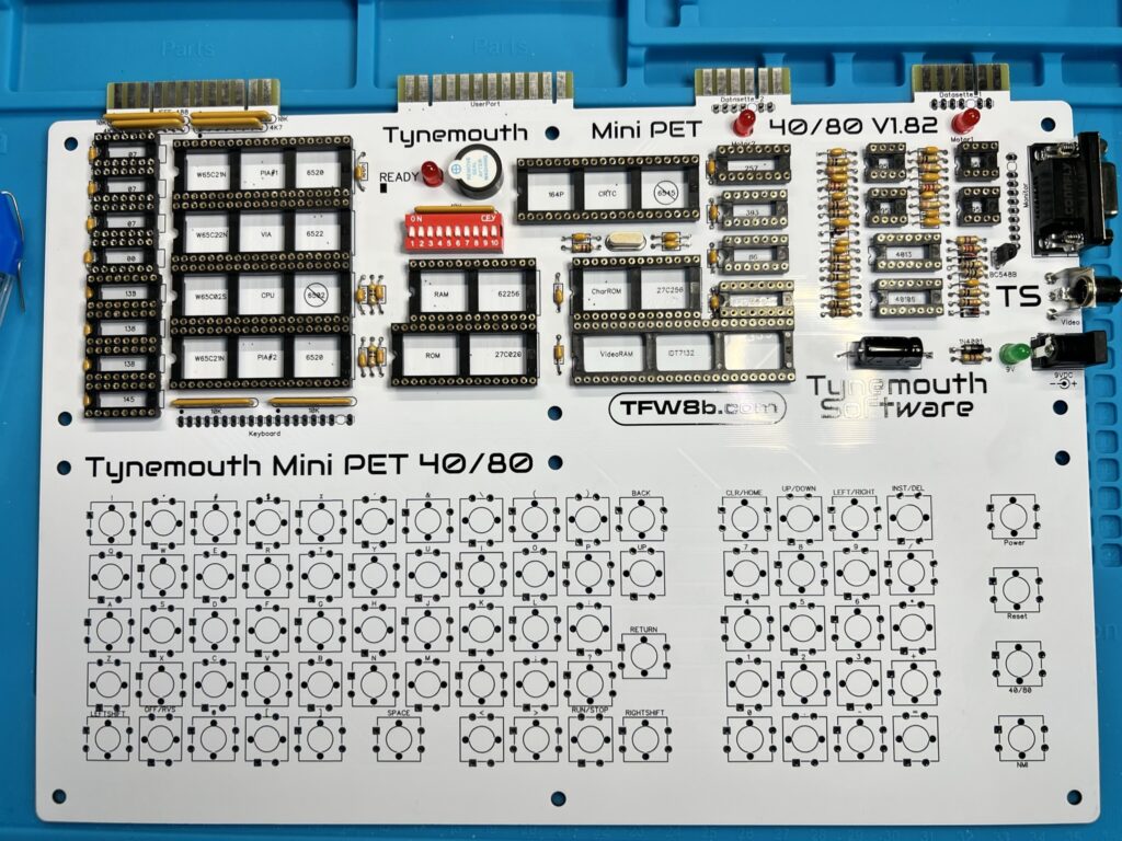
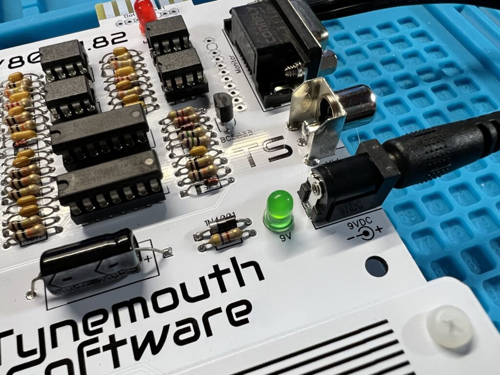
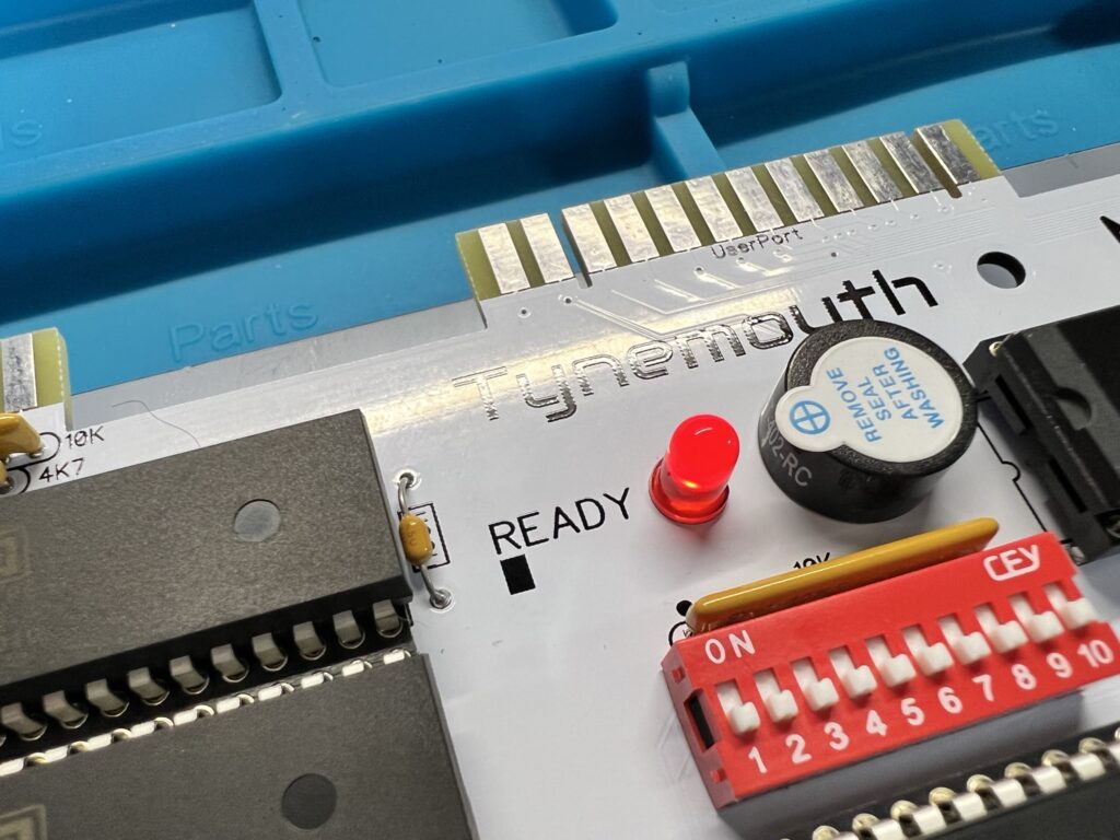
Following on from that it was time to install the piezo AC transducer (speaker) and the coloured LED’s. The green LED is used to show that the board is receiving power whilst two RED ones will indicate motor activity on the datasette ports. The other red LED is used to signify that the system is ‘ready’ and should be outputting a video signal. This is to aid in troubleshooting any issues further down the line.


Mini PET

…with added speaker and LED’s.


Building the Keyboard

Finally it was time for the part I’d been secretly dreading – constructing the keyboard. Each key is constructed using a physical key plunger attached to the mainboard, a keycap, a printed keycap label and a keycap cover.


Mini PET

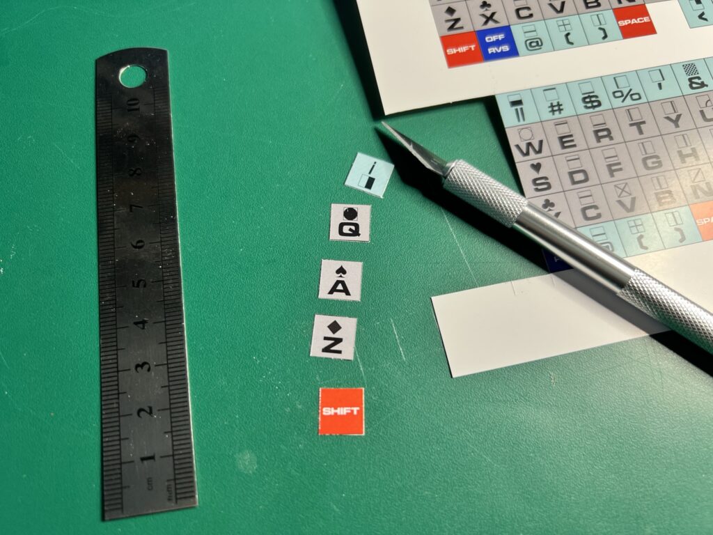
Carefully cutting out the keycap labels.


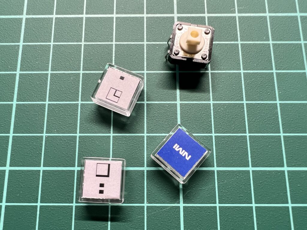
The coloured keycap labels were supplied on a glossy printed sheet and needed to be carefully cut out, one by one. For this I used a craft knife and a small steel ruler that I got out of a Christmas cracker! Immediately after cutting each label out I sandwiched it between a keycap and cover as you can see in the photo below. They were much less likely to get wafted off my desk and onto the floor like this!


Mini PET

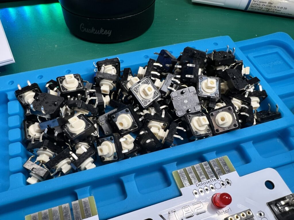
The keycaps and a plunger switch.


Now all the plungers needed fitting to the board. Thankfully from a soldering perspective their little wire legs grip the board really well so once attached they stay put.


Mini PET

This pile of plunger switches aren’t going to solder themselves…


This was a very good thing indeed as you cannot solder them to the board yet – you have to attach all the keycaps to the plungers before proceeding any further.


Mini PET

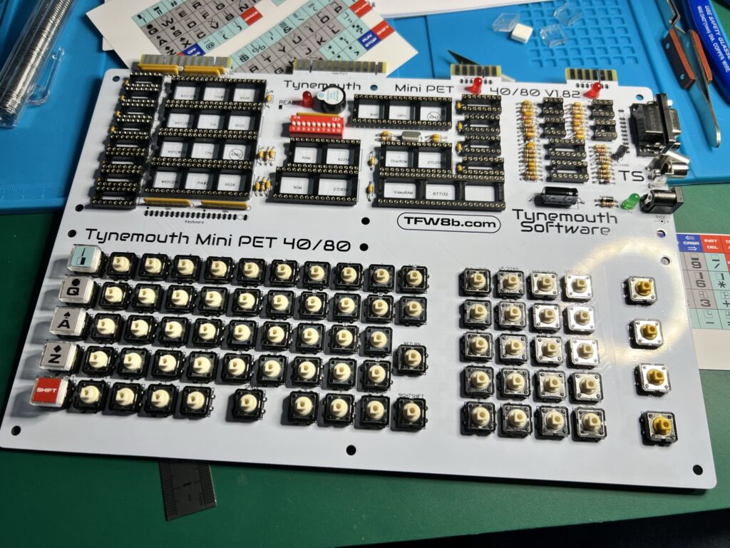
Keyboard starting to take shape now.


You also have to fit the keyboard overlay over the keycaps and fasten it to the mainboard too. This is to ensure that all the little plungers are perfectly aligned before they are permanently soldered into position.
 

Mini PET

Really starting to look like a computer now!


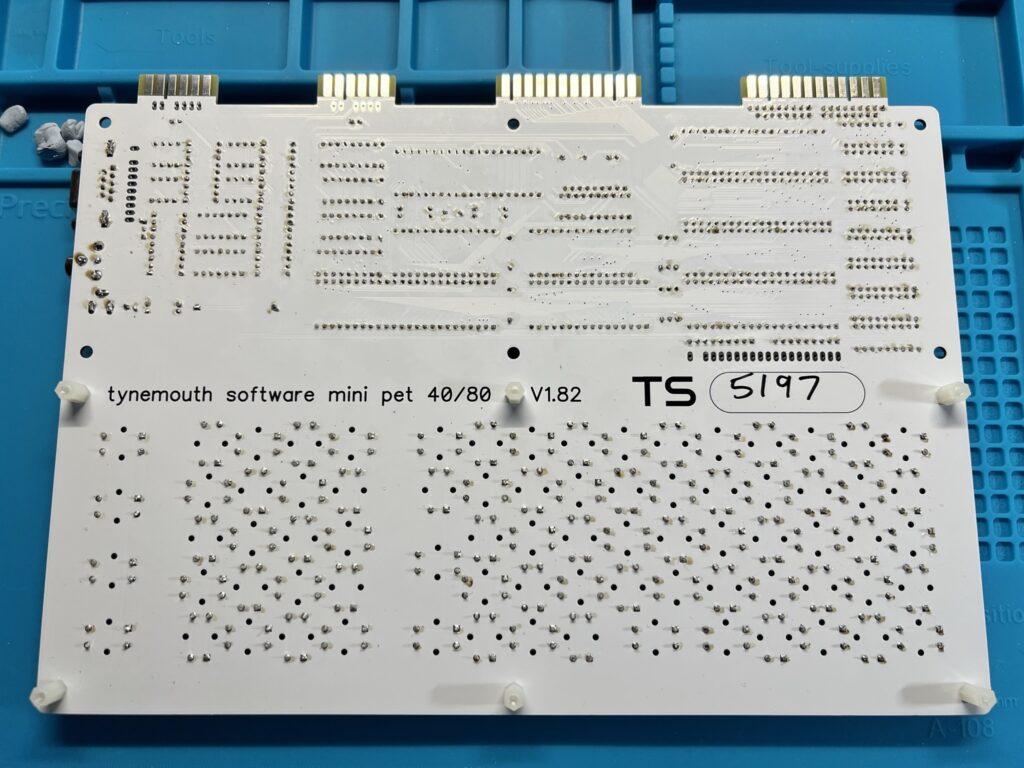
So began a marathon soldering session. Each of the 77 keys needed soldering to the board. Each key has four pins so that’s over 300 little pins that needed to be soldered. Once you get into a rhythm it’s not too bad though. Before I knew it they were all done and I was ready to begin installing the chips.


Mini PET

Each of these little pins (below the text) need soldering…


Installing the Chips


Mini PET

All of the ‘brains’ of the PET have been installed now.


Helpfully all the chips were already correctly positioned on the anti-static protective foam. Consequently it was just a matter of transposing them to the corresponding sockets on the mainboard. Most of the chips had legs that were splayed out too far and needed bending into position to fit into their socket. If I had to do this again I’d probably buy a proper tool to achieve this. As it was I used my desk surface whilst applying a slight rotational force to the chip to bend the legs into the correct position. It got the job done but not always on the first or even second try!


This slideshow requires JavaScript.


Above you can see some close-up photos of the various chips used in the kit.


Powering On!

With all the chips installed it was time for best bit of all – powering on for the first time. I was obviously pretty nervous but I plugged in the PSU and switched it on. A dim green LED lit showing the board had power but the red ‘ready’ LED wasn’t lighting up.


Mini PET

Mini PET Power LED.


For a few moments I thought I’d really messed something up, until I remembered that there’s a key on the keyboard that turns the PET on/off. Doh! Pressing that button elicited a little electronic ‘chirp’ and the ‘ready’ light lit up. Hurrah!


Mini PET

Mini PET ‘Ready’ LED.


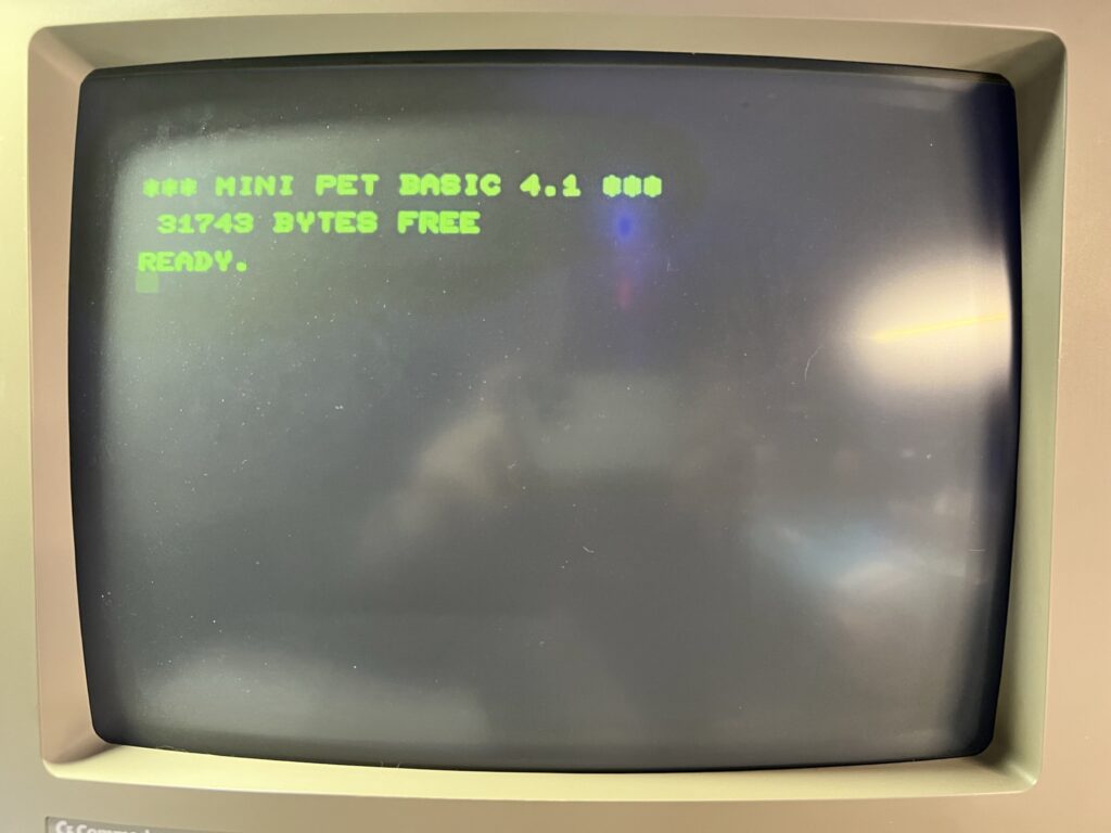
I hooked the PET up to my trusty Commodore 1084 monitor and was delighted to see a “MINI PET BASIC 4.1 – 31743 Bytes Free” message appear. So far, so good.


Mini PET

Mini PET boot screen.


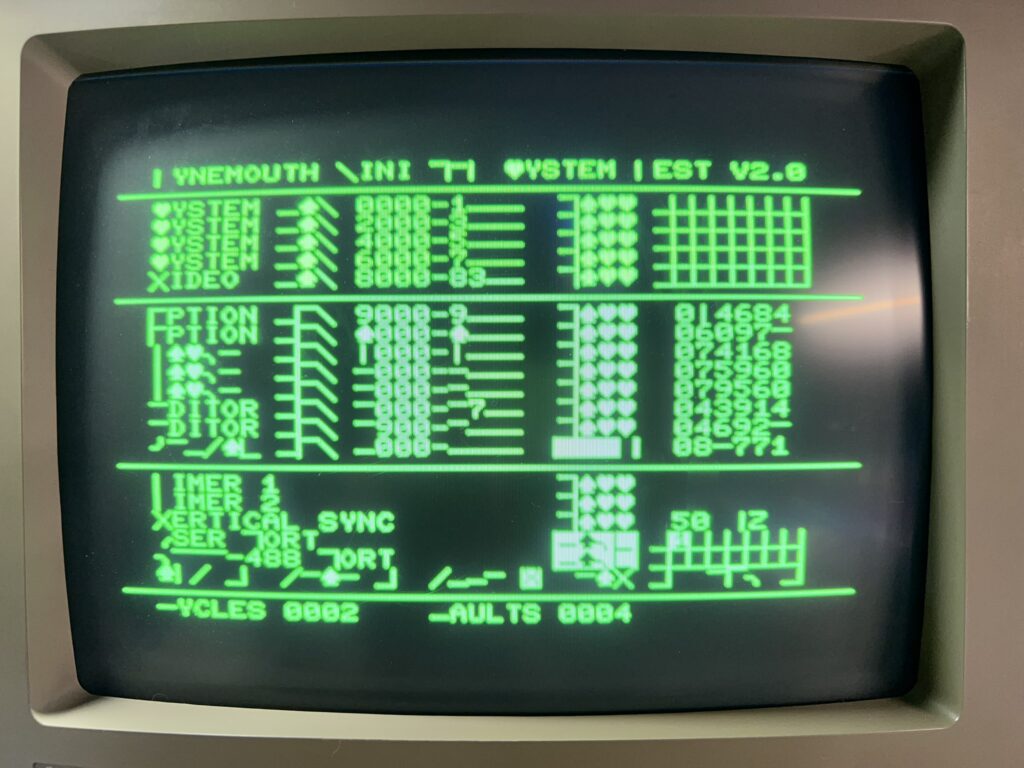
The instruction guide referred to a built in test you could run to make sure everything was working properly. It’s accessed by entering the command “SYS 40960″… I entered the command and hit Return and immediately knew something wasn’t right. All the text was garbled, showing graphics characters in place of some of the letters as you can clearly see in the photo below.


Mini PET

Uh oh – test failed 🙁


I powered it down, got out the magnifying glass and carefully inspected every single solder joint for issues. Sure enough I found 5 pins across the various chip sockets that I had somehow managed to miss completely with the soldering iron. I heated the iron back up and soldered the ones that had got away and tried running the test again.


Mini PET

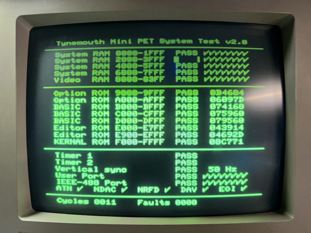
Mini PET- test passed! 🙂


Bingo! This time everything passed with flying colours. Just to be on the safe side I let the test run for a while but happily every test cycle completed successfully. Not really sure how I managed to completely miss soldering some of the pins but I was just glad it was a simple, easily rectifiable issue.

With the tests complete it was time to install my new baby inside it’s protective Perspex case. This was a simple matter of peeling off the protective film from the Perspex sheets and fastening them together with the supplied plastic stand-offs and screws.


Mini PET

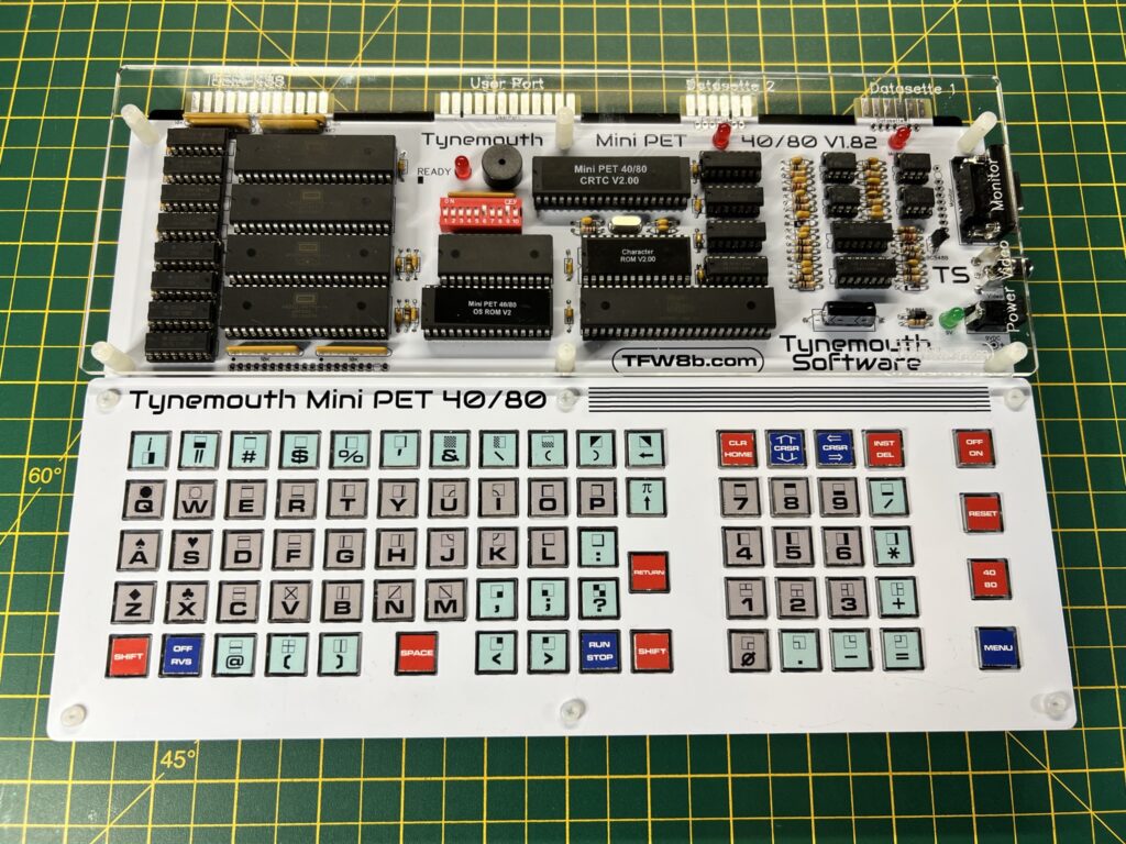
Looking good.


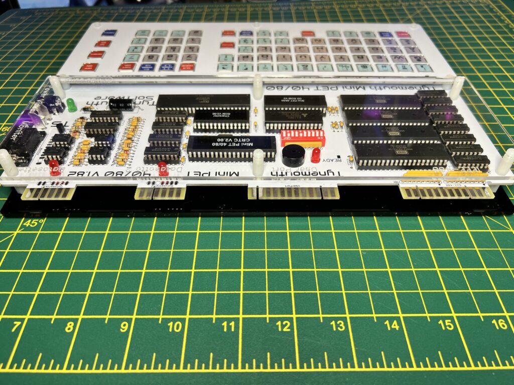
I have to say it looks amazing in its case and I love the way it has a transparent top section so I can admire my hard work. I think it looks really cool and ‘industrial’ showing the chips inside and having the little LED’s lit up.


Mini PET

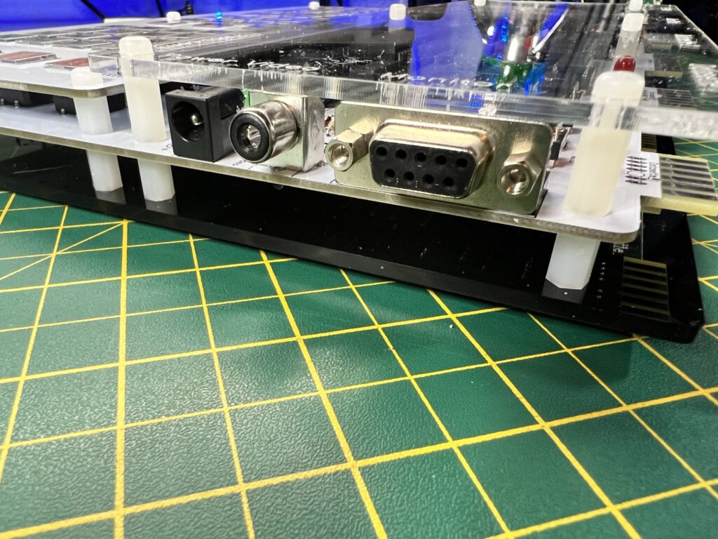
Power and video sockets.


The photo above shows, in order from left to right; the power socket, composite video output and RGB video output.


Mini PET

View of the rear ports.


This next photo shows the ports at the rear of the Mini PET. From left to right, Datasette Port 1, Datasette Port 2, User Port and finally the IEEE-488 Interface Port.


Mini PET

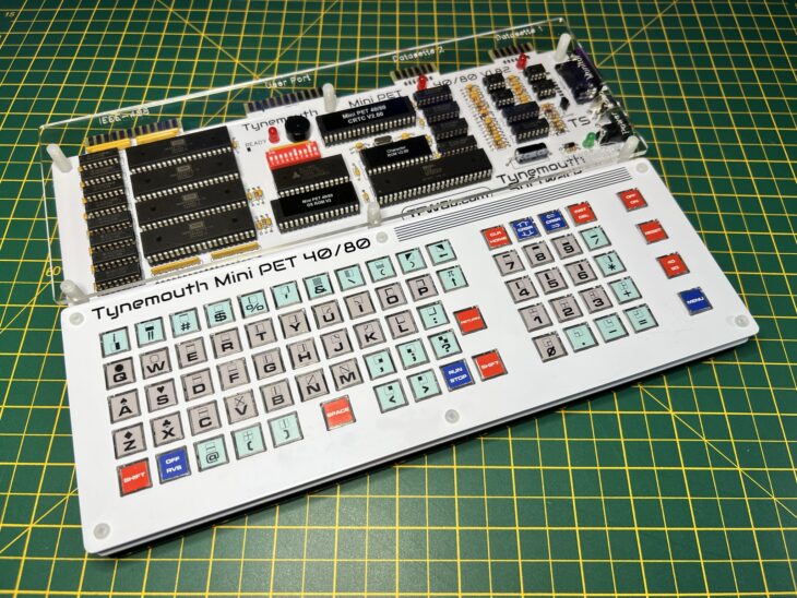
The finished kit in all its glory.


Just look at those sleek lines… Bootiful – as Bernard Mathews used to say… An additional neat touch is that the names of all the ports and sockets are etched into the Perspex case itself. You can just make this out in the photo above.


Mini PET

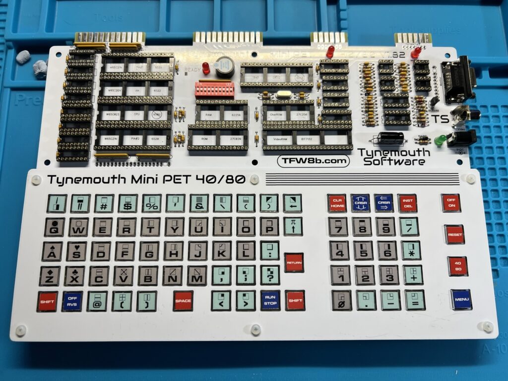
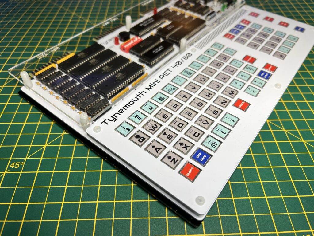
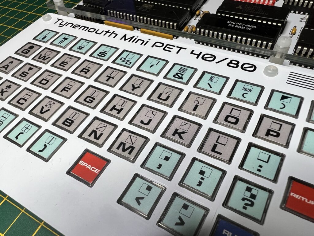
Chiclet style keyboard up close.


Here’s a close-up of the keyboard. It’s been designed to replicate the chiclet style keyboard of the original PET machines and I think it does an admirable job. It’s actually quite comfortable to type on too – I’ve certainly used worse keyboards on other devices that’s for sure!

SD2PET Device


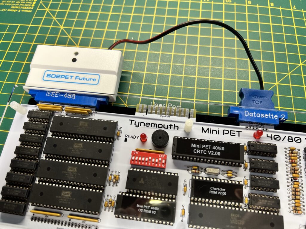
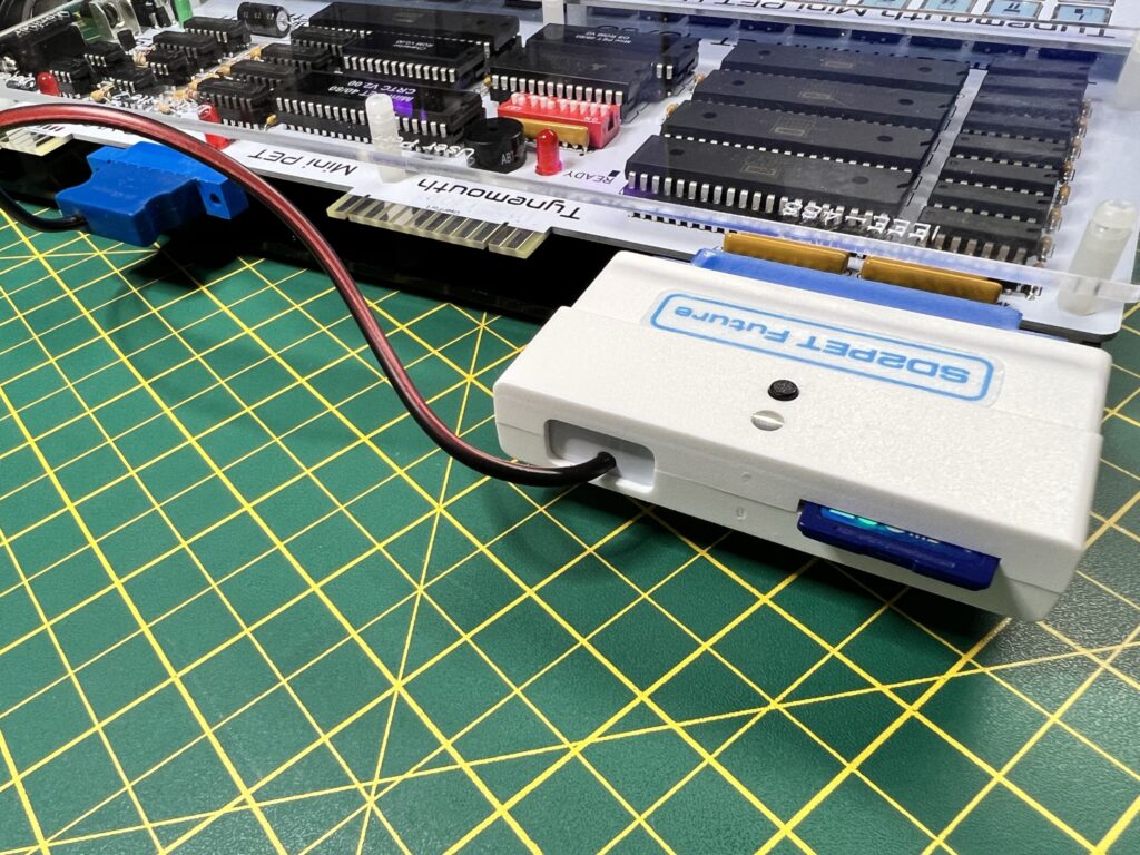
With my Mini PET build complete it was time to put it to good use. I hooked up my SD2PET device to the IEEE-488 port and Datasette 2 port (for power). This is a clever little device that fools the computer into thinking it has a floppy disk drive attached. Files on the card appear as virtual disks to the PET.


SD2PET

SD2PET plugged into back of Mini PET.


The SD card must be formatted as FAT32 which is easy enough to do on a Windows 11 PC. Next I transferred a few PET games and demos to the card, inserted it into the SD2PET and fired up the Mini PET.


SD2PET

SD2PET – Rear view.


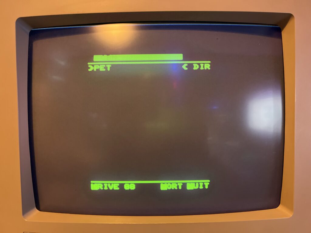
The Mini PET has a nifty little feature if you press the dedicated MENU key (bottom right).


SD2PET

SD2PET File Browser.


It brings up the file browser for the SD2PET allowing you to select a program to run straight away as shown in the photo above. By the way, I apologise for the quality of the photos in advance. I found it very hard, if not impossible to achieve an exposure that could both capture the bright green luminous display on my 1084 CRT and avoid the flickering scanlines. The images look pin sharp and vibrant in real-life but not so much in my photos…


Demos and Games


PET Games

Space Invaders


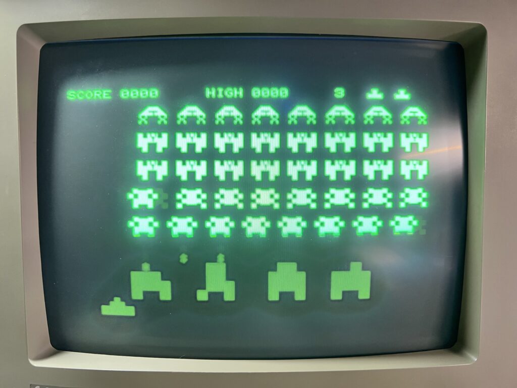
I found a really terrific version of Space Invaders that both looked and sounded the part and was as addictive as ever to play with keyboard controls.


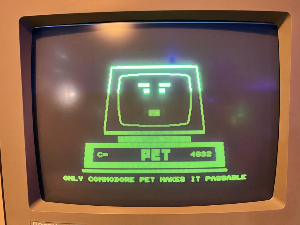
PET Demo

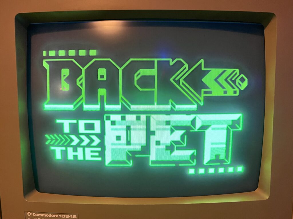
Back to the PET demo.


I also ran a few demos and was particularly impressed by one called “Back to the Pet”. It featured some pretty groovy music given the hardware it was running on and some flashy graphics including parallax scrolling. This demo was only released this year so it really pushes the limits of what the PET can achieve. I certainly never thought the humble PET was capable of something like this!


Back to the PET demo.

Another Back to the PET capture.


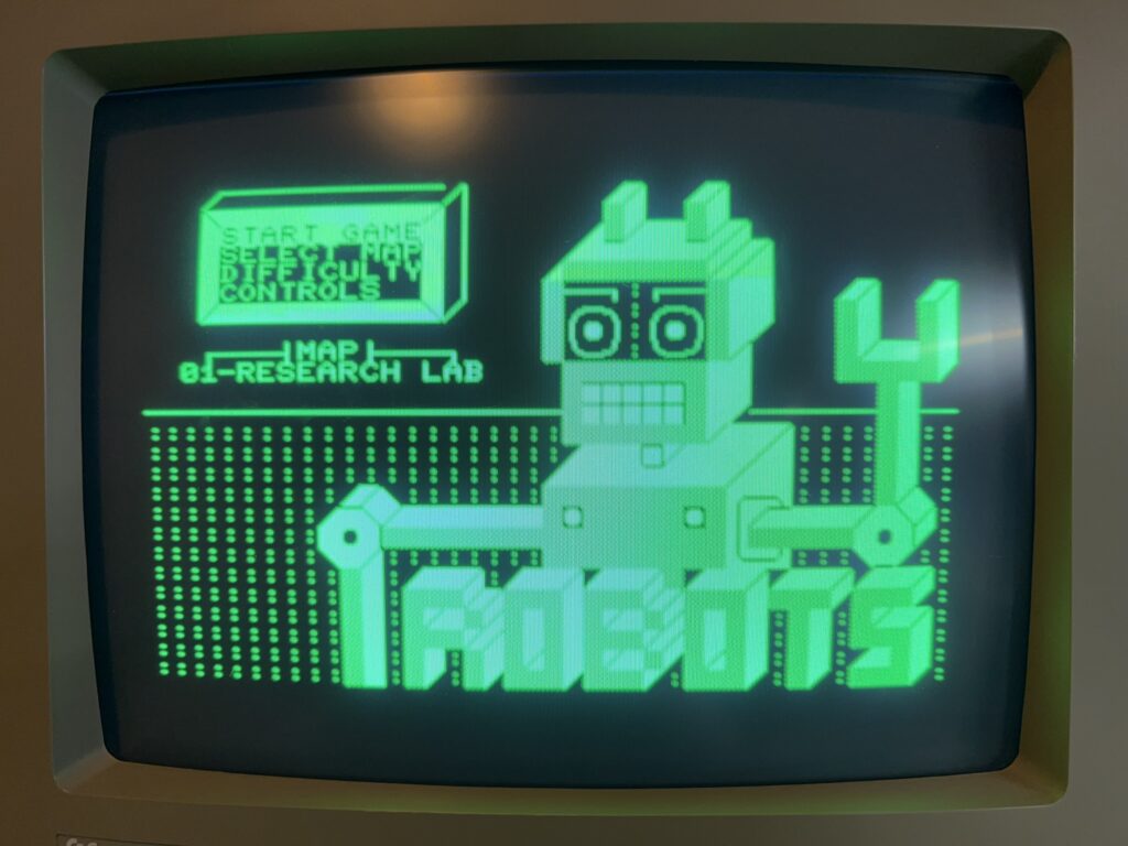
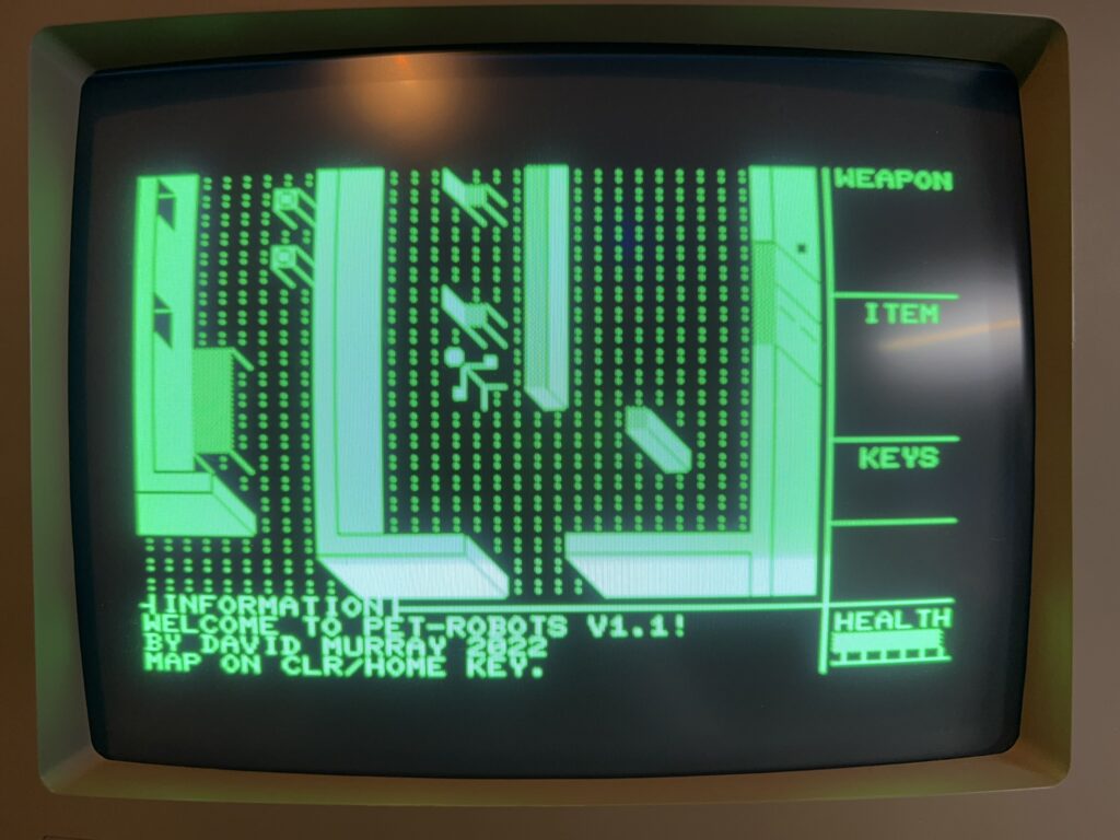
I also tried Attack of the PETSCII Robots which felt appropriate given the name and was pretty impressed with how well it ran.


Attack of the PETSCII Robots

Attack of the PETSCII Robots Title Screen.


This game actually allows you to swap out the physical character ROM chip in order to get some enhanced custom graphics. This involves programming an EPROM and is something I might look into as a project for the future but right now I was content to just play the game ‘as is’.


Attack of the PETSCII Robots

Attack of the PETSCII Robots Game Screen.


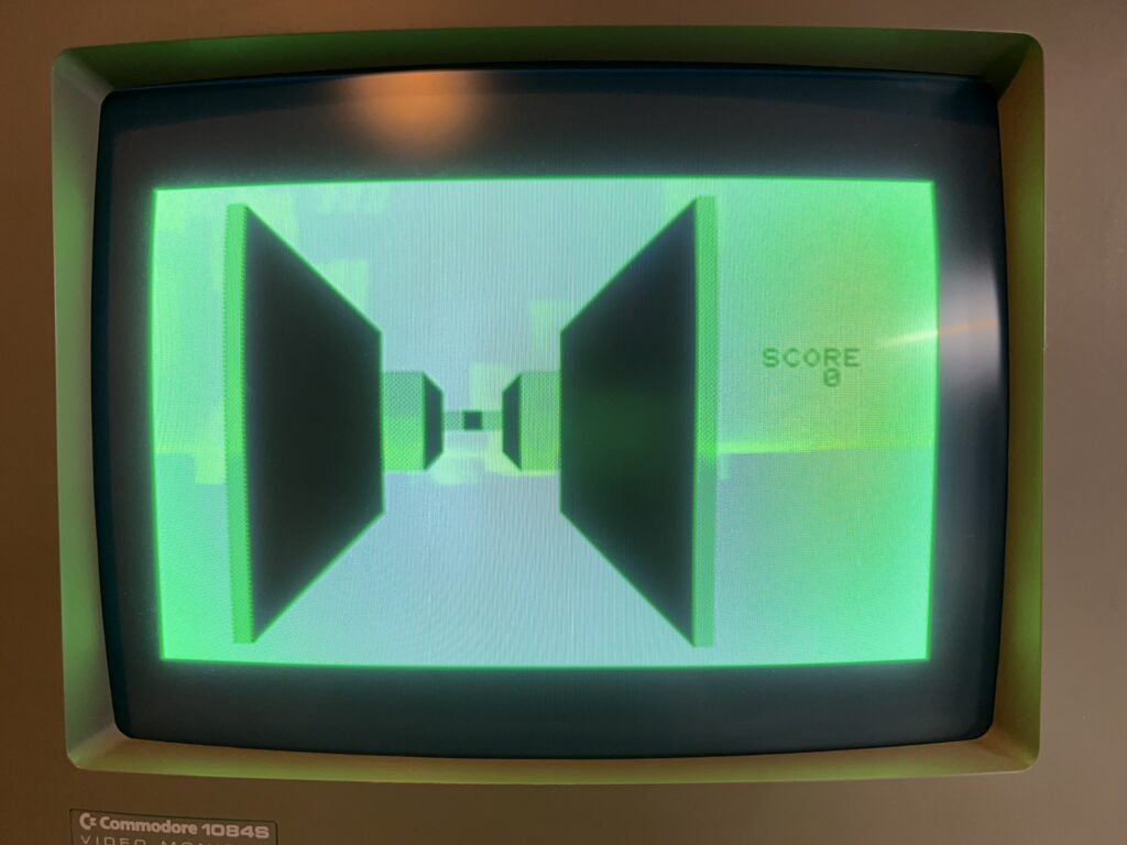
At this point I remembered that a copy of 3D Monster Maze was included in the box so I hooked up my Datasette to Port one and loaded it up.


Graphically this is quite a simplistic game but it ran really well.  It was easy to control with the keyboard and I had a fun experience while it lasted.


Rounding Off

All in all I’m super impressed with the Mini PET. It was much easier to build than I’d anticipated and I definitely wish I had gotten round to making it sooner instead of putting it off. Although it probably cost almost as much as a real Commodore PET on eBay it’s built with new components so should be much more reliable. It’s also a fraction of the size of those behemoth PET machines plus I’ve had the satisfaction of building it myself.

My experience of building the Mini PET computer has certainly left me a lot more receptive to the idea of building my own retro machines in the future now too. If they ever offer a build your own Commander X16 kit then I’m all in!

The Future

TFW8b sell a hardware expansion for the Mini PET and some more games on cassette so I’ve ordered these and will post some more updates when they arrive. I’ll also be keeping a look out for any books or magazines containing BASIC listings for the PET computer so that I can have a go at typing them in in true 1980’s style!