This is a guide to repairing a Roctec floppy drive for an Amiga 500 computer. I thought I’d write this up as much for my own benefit as other peoples so I can refer back to it in another 20 years! LOL.
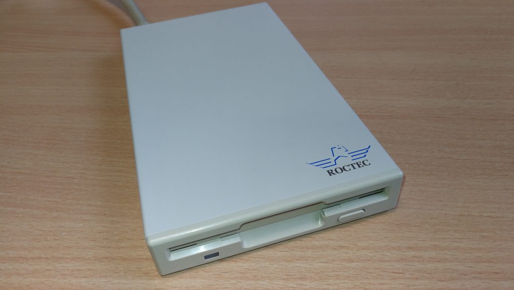
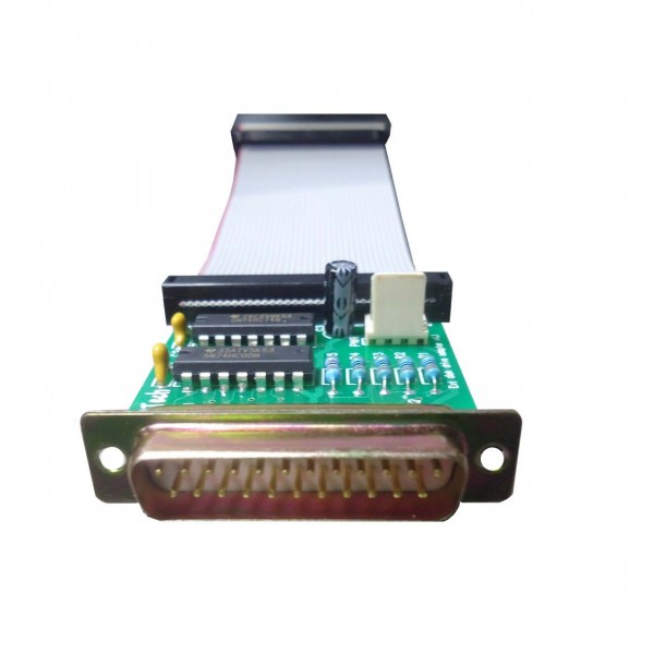
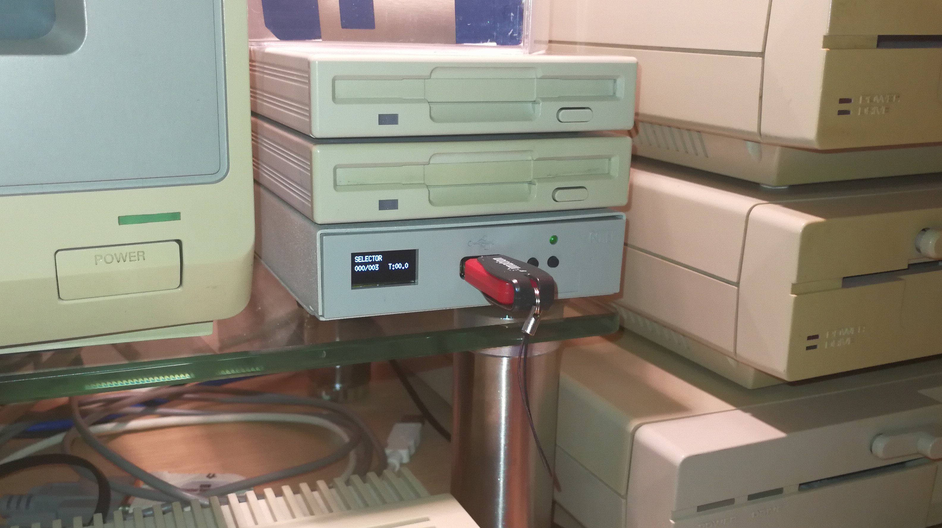
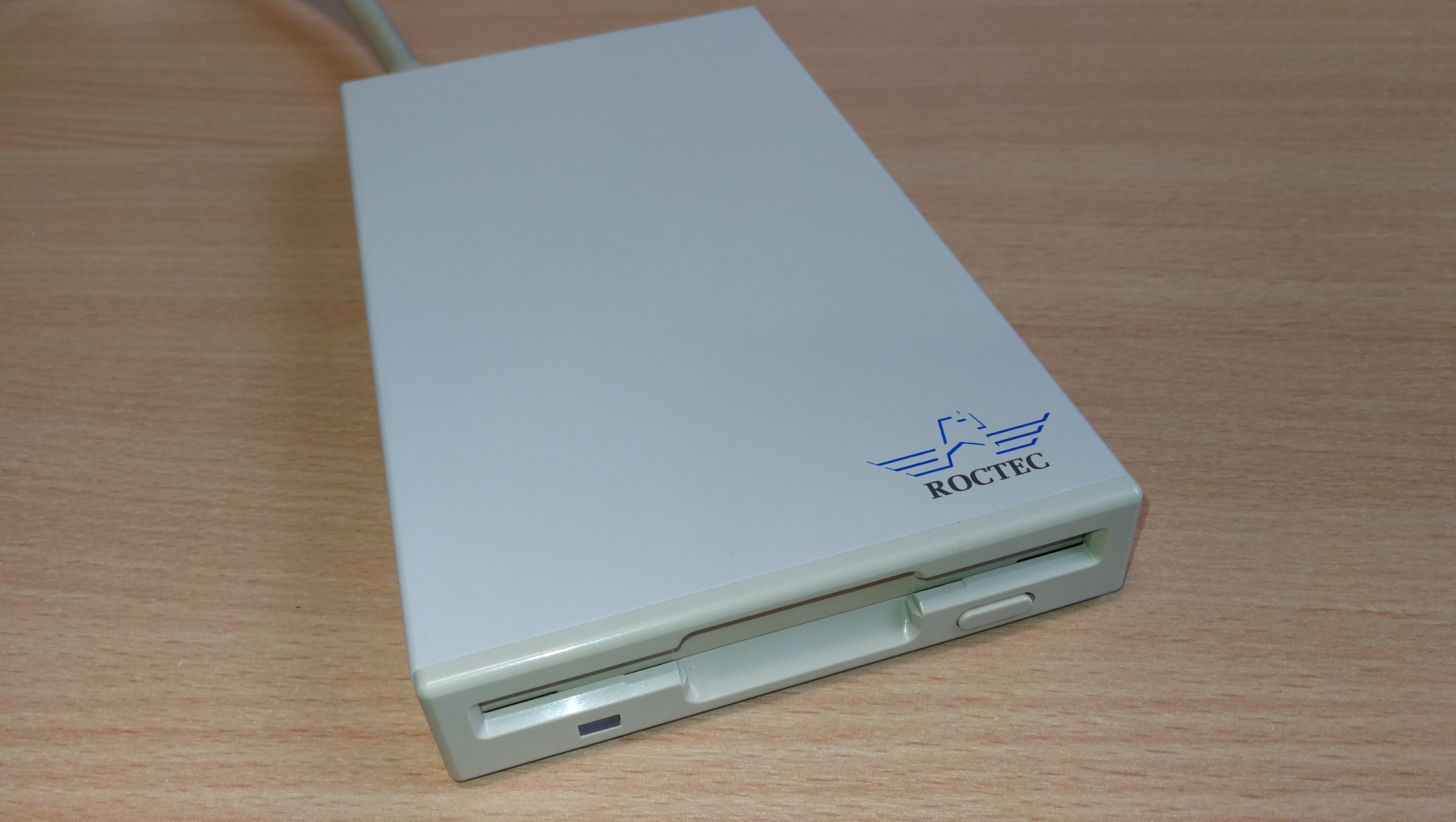
Roctec Amiga external floppy drive
If you ever pop a disk in your external Roctec drive and hear a strange whirring noise and can’t read any of your disks then the chances are you are suffering from a perished or broken drive belt.
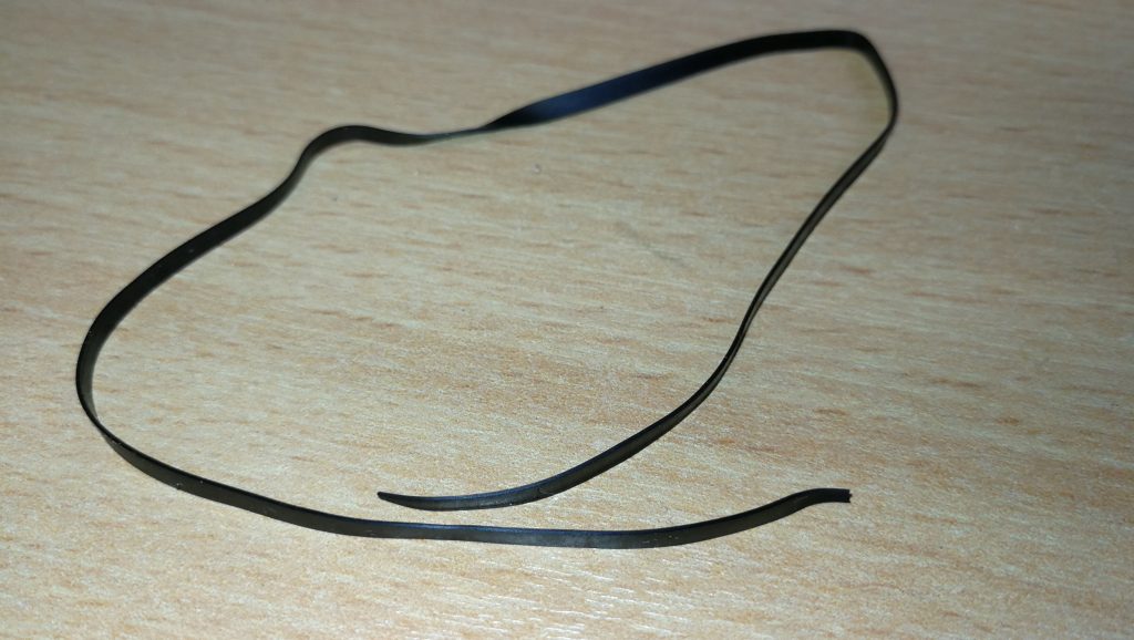
Perished Drive Belt
These drives use a rubber belt to connect the drive motor to the spindle hub. The rubber belt only has a finite life and given most of these drives are getting on for 30 years old now it’s hardly surprising that they expire.
No tension in old perished belt
The good news is that it’s pretty easy to replace them and I’ll give an overview of what you need to do here.
Getting Started on the Repair
The first thing you need to do is undo the 6 screws on the underside of the drive case using a small philips screwdriver.
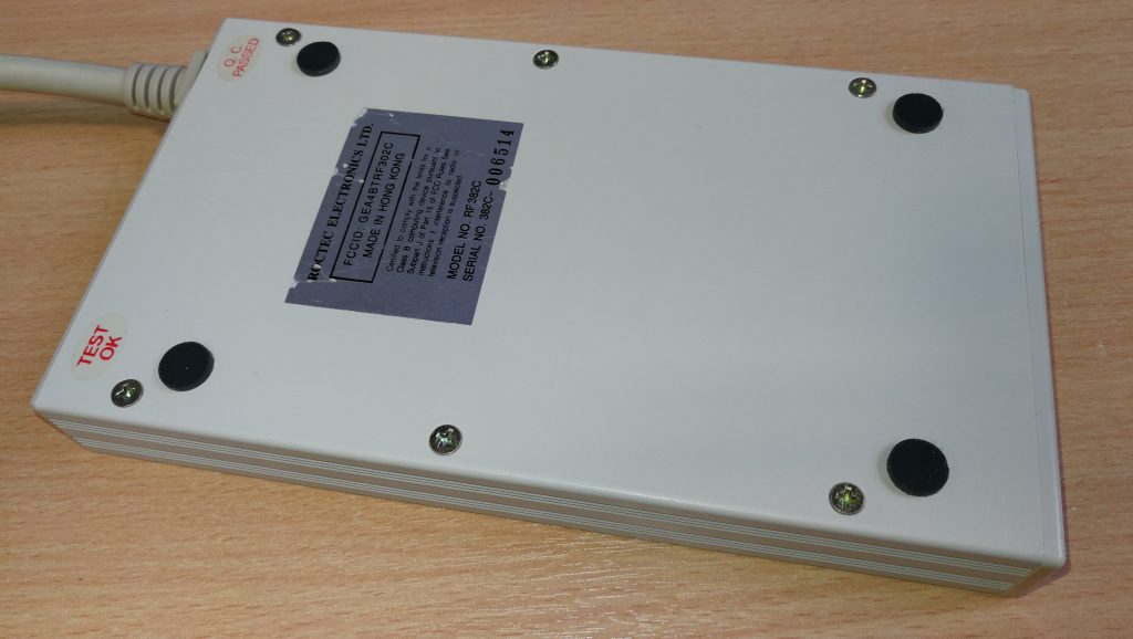
Remove these 6 phillips screws.
This particular drive case is made from a solid metal rectangular tube so you need to slide the floppy drive out. The aim here is to slide everything out of the BACK of the case. The first step is to gently slide the floppy drive forward out of the case far enough to detach the plastic fascia from the front of it. Unless you do this it won’t slide right into the case and out the back. There are 2 small tabs on each side of the fascia which you can gently bend with a small flat-bladed screwdriver and it will pop right off. Don’t force anything or it will break – it should come off easily.
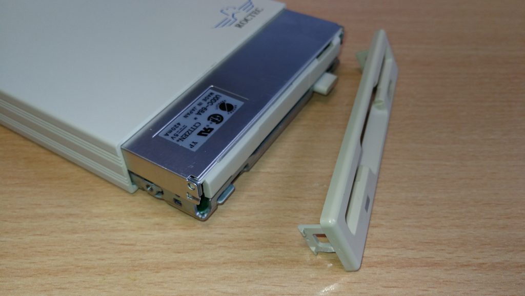
Drive Fascia removed
Now you need to prise the back part of the drive out of the case using something thin enough to slide into the tiny gap between the case and the backplate, I found the blade of my pocket knife to be perfect for this but be careful not to injure yourself or damage the plastic/paint on your drive! Once you’ve got it moving slide it out slowly (a slight side to side wiggle can help here). It will be attached to the floppy drive via a ribbon cable so keep going until you’ve got the floppy drive out too.
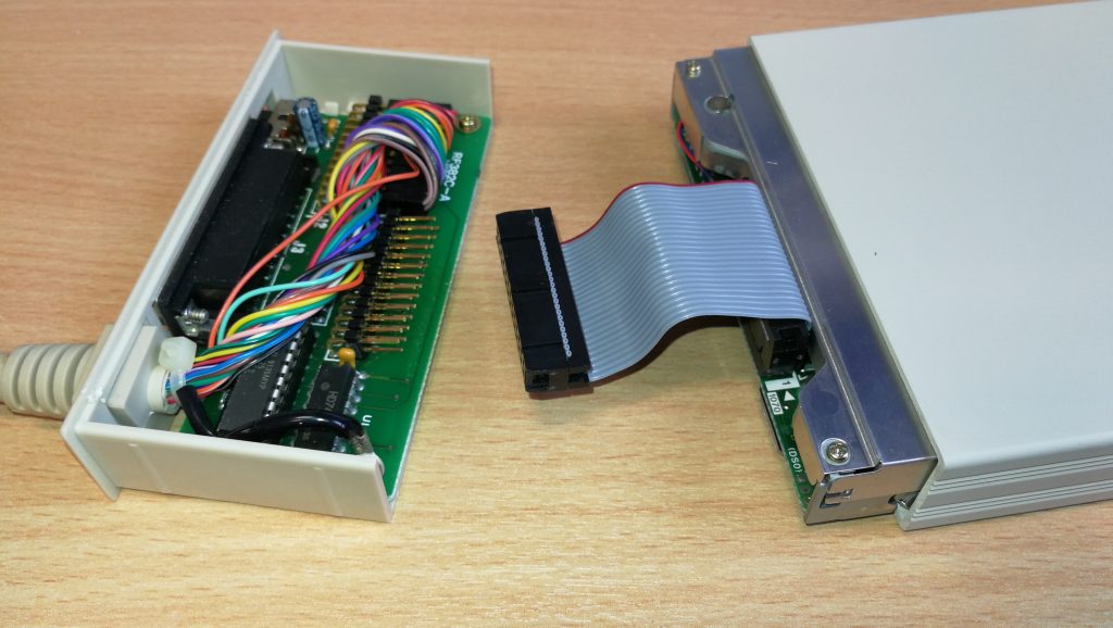
Roctec floppy drive detached from controller board
The floppy drive has a thin metal cover that protects the mechanical innards and it is held in place by some little tabs on the edges and a solitary screw at the back right (when viewed from the front).
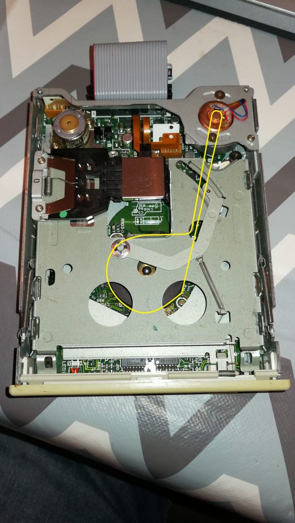
Roctec Floppy Drive Rubber Belt Path
Replacing the Belt
Once the top is off you can see the drive mechanism, motors, heads and so on. Carefully remove what’s left of the old belt with a pair of tweezers. Be careful not to touch the drive heads with anything metallic or you may damage them. The photo above shows the path the rubber belt follows, indicated by the yellow line.
The next step is to remove the drive motor which is attached to a metal bracket that runs across the back of the drive. It is held in position by one screw in the far left corner and another on the right a few cm down from the corner. Don’t touch the two screws with the large flat heads either side of the motor. Be careful you don’t pull the bracket too much as there are two tiny wires connecting the motor to the circuit board here so be careful to support the bracket whilst you are handling the drive to replace the belt.
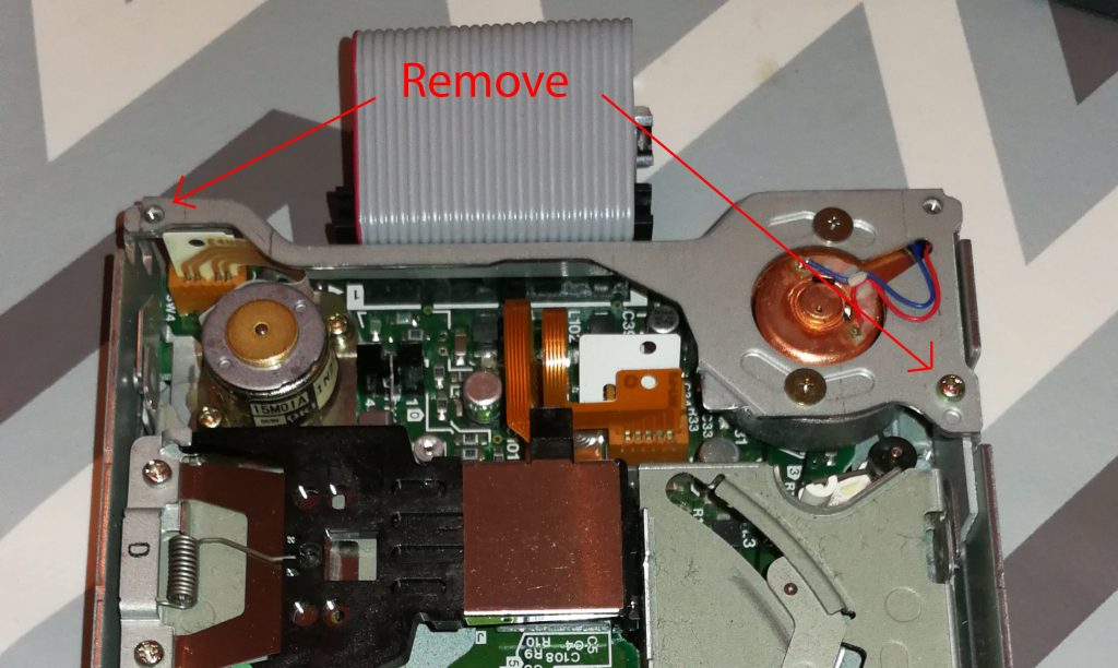
How to detach the motor and bracket
Drive motor and bracket removed
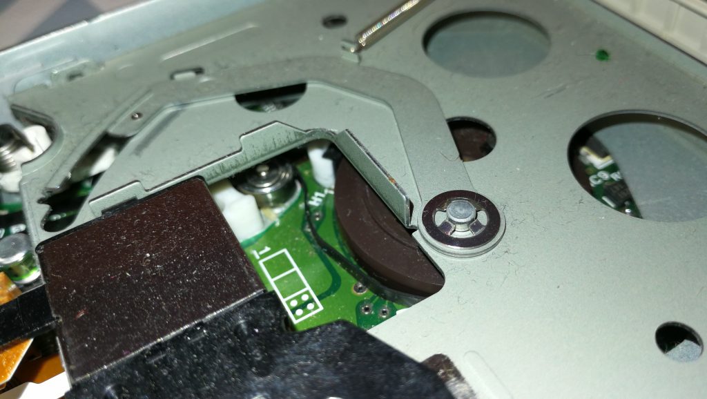
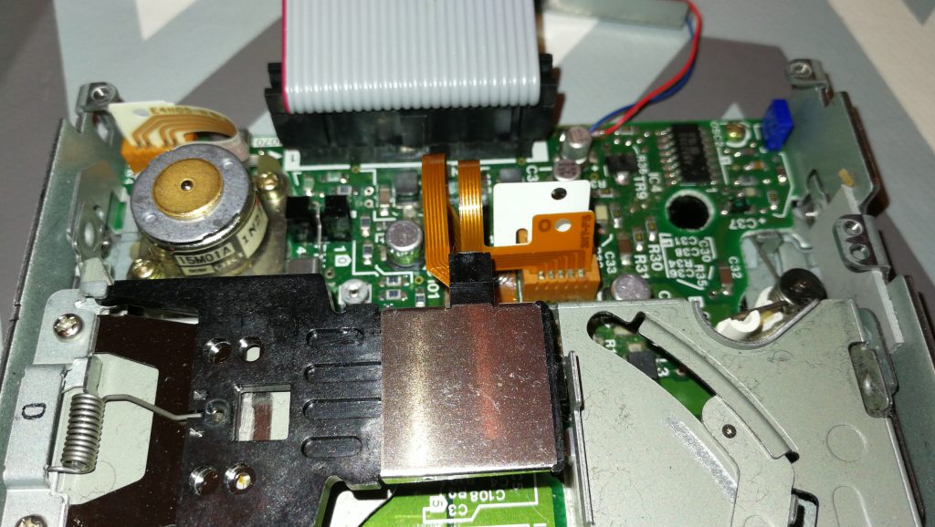
Once the bracket and motor are out of the way you can carefully thread a replacement belt around the large drive wheel, small tension wheel and keep a loop ready at the top right to go on the motor spindle. Follow the yellow path in the earlier photo and take your time as it can be a little tricky to get the belt into place. A small flat bladed screwdriver and a pair of tweezers are essential for this. Don’t forget the belt needs to thread behind the small silver pully wheel as this is what tensions the belt.
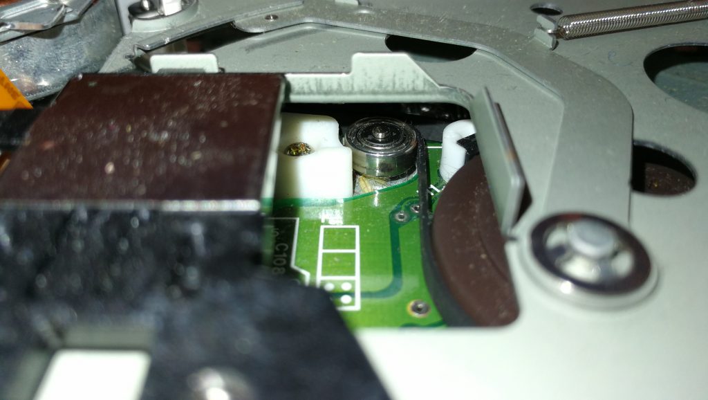
Close-up of the small tension wheel you need to thread the belt behind
Once you’ve got it threaded around the wheels correctly you need to get the final loop onto the motor spindle. It helps if you grab the loop with some needle nosed pliers here and pull it taught with one hand whilst guiding the motor spindle into the loop with the other. Once this has been achieved (it may take a few goes as it’s quite fiddly) place the bracket back in place and rotate the large drive wheel slowly and check the belt stays on, is running where it should and isn’t fouling any components.
Look carefully through the tiny gaps in the top of the drive motor you should be able to see the motor armature slowly rotating as you move the belt. If it is then job done, time to put it all back together! If it isn’t then don’t fret, just double check the belt is following the correct path, isn’t twisted anywhere and hasn’t slipped off any of the wheels.
Congratulations, your Roctec drive should now be fit for active duty for another several years now!