Introduction
Unlike the Amiga 1200, the A500 was never designed to allow the fitment of an IDE Hard Disk Drive (HDD) inside it so naturally it never included an HDD activity LED. For the longest time this was never really an issue. Sidecar expansions such as the A590 were the only way to add HDD’s to the A500 and they came with their own drive activity LED. However, now that many owners are fitting expansions like the Vampire into their Amiga 500, things are a little different. These new devices facilitate the use of 2.5″ HDD’s or Compact Flash (CF) cards inside the casing of the A500, something that was never possible before.
The problem with this is the lack of a drive activity light. It can be quite disconcerting at times when you turn on your ‘Vampired’ Amiga 500 and nothing appears to happen. You sometimes wonder if it’s actually booting up or simply frozen. The same issue crops up whilst loading a game or running a program. There’s simply no way to tell if your Amiga is doing anything, especially if you’re using a CF card as they are completely silent. At least if you have a 2.5″ HDD they do at least make some sounds whilst being accessed.
Wouldn’t it be great if you could add a hardware activity light to your A500 to solve this issue? Well, recently I stumbled across a nifty little mod from Arananet that claimed to allow you to do just that by using the Amiga 500 floppy disk activity LED to show IDE HDD/CF activity. It’s called the ‘IDELED’ and is only €7 plus postage so I ordered one and sat back waiting for it to arrive. (Direct link to the Amiga 500 IDE activity LED can be found here).
Incidentally, if you fancy making this modification yourself all you need is a phillips screwdriver (to open the A500 case up), some wire cutters/strippers and a soldering iron. Don’t worry if you’re not an expert solderer, I’m rubbish at soldering but this is very basic stuff and should be well within most peoples capabilities.
A closer look at the IDELED device
The device arrived in a little anti-static bag with no instructions. It’s a tiny little 1″ square circuit board that incorporates an 8 pin socket one one side and 8 pins on the other. There is also a small hole for you to solder a wire to, plus a few components that allow it to ‘do its thing’.
Getting Started
The IDELED is designed to sit between the Amiga 500’s keyboard connector and the keyboard cable. This gives it access to the floppy drive LED circuit and allows that to be used as an IDE activity LED in your Amiga 500. After opening up your A500 the first thing you need to do is carefully unplug the keyboard connector, lift away the keyboard and set it to one side.
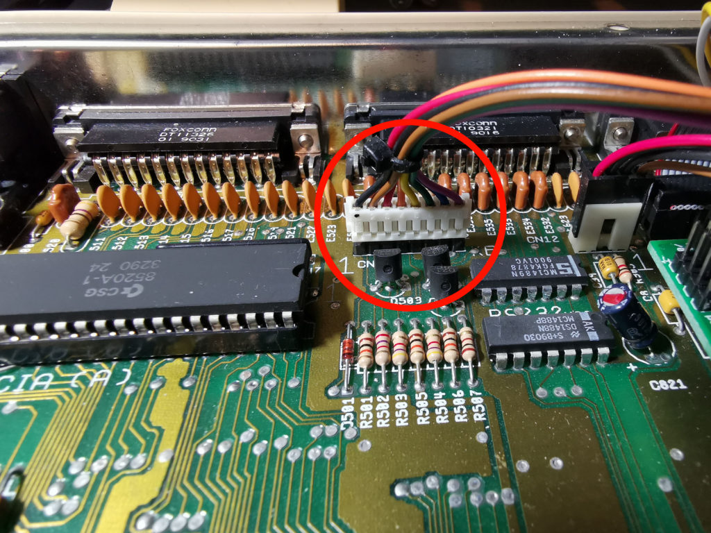
Unplug the keyboard connector (circled in red).
You’ll then have access to the 8 pin keyboard connector on the mainboard which will look like this:
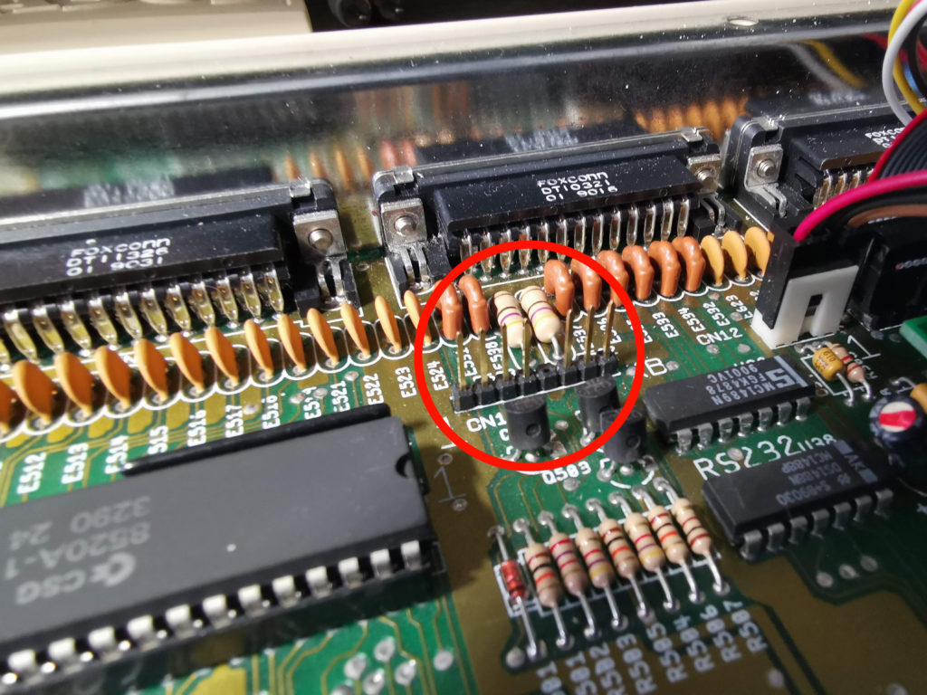
Keyboard connector pins
Next you need to attach the IDELED board to the keyboard connector pins on the mainboard. Make sure that you connect it the correct way around – orient the board so that the keyboard connector is at the back if you are looking at it from the front of your Amiga. It should then look like this:
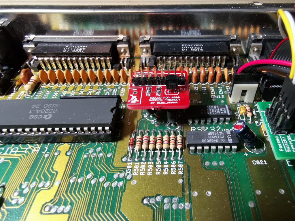
IDELED fitted to keyboard connector
At this point I connected the keyboard to the pins on top of the IDELED board. You might want to leave doing this until after you’ve soldered the connecting wire but I needed to experiment a bit and wanted the A500 powered on and the LED’s working. At this stage the project looked like this:
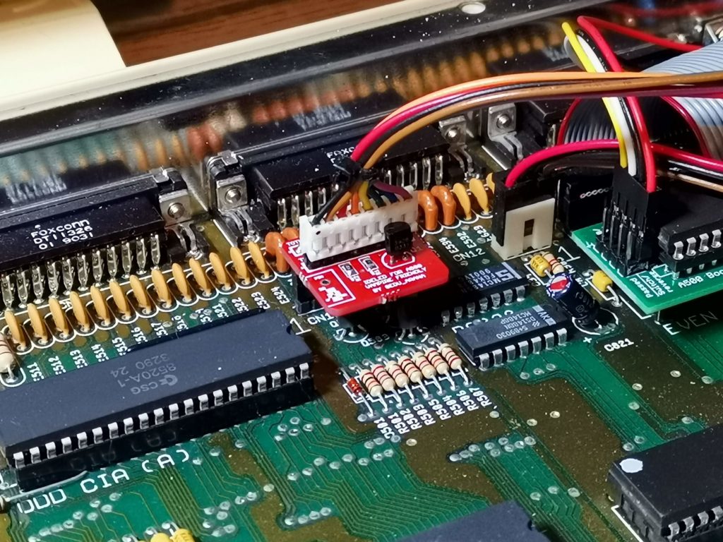
IDELED board fitted between mainboard and keyboard cable
Solder time
The next job is to attach a short wire to that little solder point on the left side of the IDELED board. The wire needs to be long enough to reach the IDE connector on top of your Vampire (or other accelerator card) with enough slack so that it’s never under any strain if you have to move things around in the future. You will need to strip off a few millimeters of insulation from each end of the wire before you go any further. It’s much easier to do this before one end of the wire is attached to anything. I’d also suggest ‘tinning’ the exposed wire each end as this makes soldering them easier.
Insert one stripped and tinned end of the wire into the little hole in the board and apply a blob of solder. You should now have something looking like this:
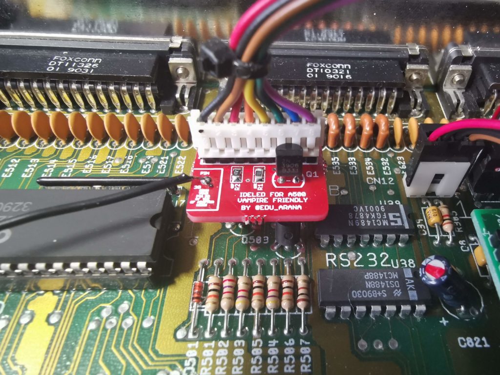
IDELED board with ‘activity’ wire soldered on
Locating pin 1 and 39
The other end of the wire needs to go to ‘pin 39’ on your IDE adapter. This is the pin responsible for transmitting drive activity. If you have a CF adapter like mine (pictured below) then you should be OK to just hook the wire up to the same pin as I did.
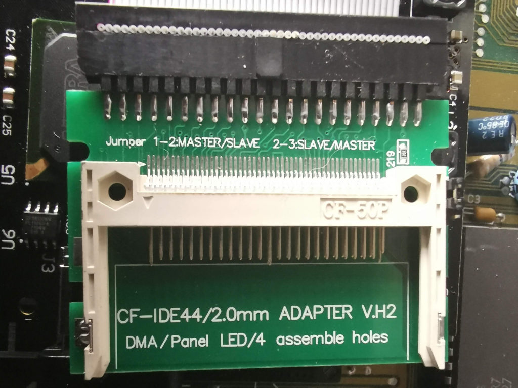
A closer look at my IDE CF adapter (without CF card fitted)
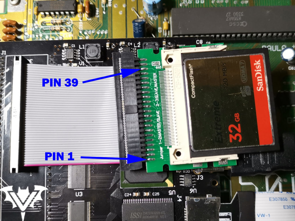
Locations of pins 1 and 39 on my 44 pin IDE adapter
To locate ‘pin 39’ on my adapter I used the 44 PIN IDE connector diagram below for reference. Note the way the pins are numbered – it alternates up and down with 1 top left, 2 bottom left, 3 back to top row and so on. My particular adaptor has the upper row of 22 PINs connected to the top of the circuit board and the lower row of 22 pins to the underside.

2.5″ 44 PIN IDE pin layout & numbering
Provided it was connected up the correct way round originally, the purple edge of the ribbon cable indicates which side ‘pin 1’ should be. Thankfully the Vampire card clearly indicates where ‘pin 1’ is (see the little ‘1’ above the bats head in the photo above) so my cable was oriented correctly. Once I was sure of the location of ‘pin 1’ it was a simple matter of counting along to identify ‘pin 39’. Obviously if you have a different kind of adapter then you will have to confirm its location yourself. Hopefully the information above will help you out.
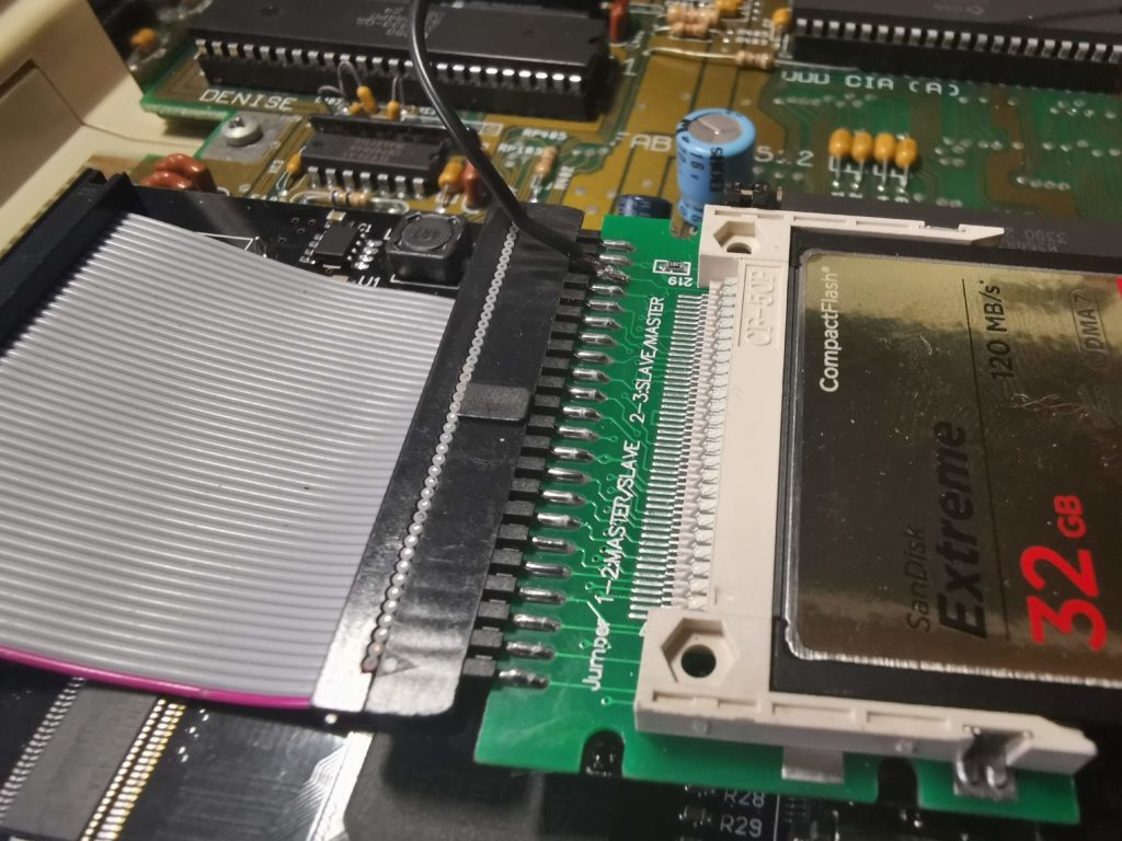
Wire soldered to pin 39 – not the prettiest soldering job in the world but it does the job.
The completed modification
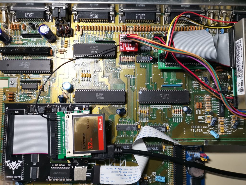
View showing the completed modification in its’ entirety.
Assuming you’ve connected everything up correctly (check before you screw the case back together), you should now how a fully working IDE activity LED on your A500.
Demonstration
In the video below you can see my Amiga 500’s new IDE activity LED flashing away whilst it boots into Workbench. The loud clicking sound is just my empty floppy drives clicking – the anti-click software doesn’t run until workbench has finished loading.
I’m really pleased with this mod, it was cheap, pretty simple to implement and above all else, really useful. No longer will I be in the dark about when my CF card is being accessed!
But wait, there’s more!
When you pop in a floppy disk the activity LED still flashes away as usual so there is no loss of functionality. Quite the opposite in fact as the LED even flashes when I use an SD card (the Vampire supports SD card storage too) which is totally awesome and something I definitely wasn’t expecting. An added bonus is that because Commodore simply labelled the A500’s floppy activity light as ‘Drive’ it’s still labelled correctly! How’s that for future-proofing!?
Anyway that about wraps this article up for now. I do hope you found this article both interesting and useful. If you did, please let me know by leaving a comment below, I’d love to hear from you.
Discover more from Lyonsden Blog
Subscribe to get the latest posts sent to your email.

Thanks for the review of my product. This was one of the best installation guides that I ever saw on Amiga.
Regards,
Edu.
Thanks, and thank you for creating the IDELED in the first place!
Does this also work with pin 39 from a 40pin ide port?
Hi Andreas,
Yes it would still work – pin 39 on both types of connector is used for LED activity. The extra 4 pins on a 44 pin IDE port are used for power leaving the pinouts of the remaining 40 pins exactly the same. Hope that helps.
Thanks a lot! 🙂
Just picked up the LED kit plus a few other bits from Arananet – wouldn’t have known about it if I hadn’t seen this post. Thanks!
No problem, glad you found it useful.
Hi There, Just ordered mine. I want to connect it to the Indivision ACA500Plus – Do you know what pin on a 50 pin CF card I need to attach it to? I believe its pin 45?
Thank you.
Hi Darren,
Sorry not really familiar with that expansion but I would imagine it’s similar to my Vampire in that it’s the pins on the IDE interface (that the CF card plugs into) that you need to identify? They usually only have 44 pins in total.
Hi Steve,
Thanks for the swift reply. There is no IDE header on these. They are standard CF interfaces surface-mounted directly onto the card. I’m guessing that there must be a standard pin value for the activity led but looking at schematics for CF pinouts isn’t immediately clear. Thanks anyway for the update – I’m sure I’ll find it 🙂
No problem. Maybe fire an email off to Individual Computers and explain what you are trying to do and see if they’ll identify the pin you need? In my experience most retro computer suppliers are really helpful people.
Thats a really good point 🙂 Thanks again Steve for the help.
This won’t work with any RGB2HDMI expansions on top of denise- of course vampire owners won’t be affected.
Is there a hack/mod that could do this without sitting so high?
PS_ Edu’s webstore is offline currently… (?)
How about using a bunch of male to female Dupont cables and lead them off to one side to keep the IDELED board out of the way?
I got a notification that the Edu site was down a while ago when my links on here stopped working. It was supposed to be back up on 7th so not sure what’s going on there. Maybe he’s just taking a break? Anyway, hopefully it will be back online soon.
Hi, Enjoyed watching your video and I will definitely be getting one of these boards..
With a few companies making new remakes and modifications on the Amiga 500 500+ case, with sd and hdmi slots in the right hand side of the keyboard, its a shame no one adds an extra space for a third led, like an a1200. With a slight modification on the original keyboard, I`m sure this could be done.