Lyonsden Blog

Archive - March 2018

Adding an SD Card Slot and HDMI port to an Amiga 500

SD Card Slot and HDMI port to an Amiga 500

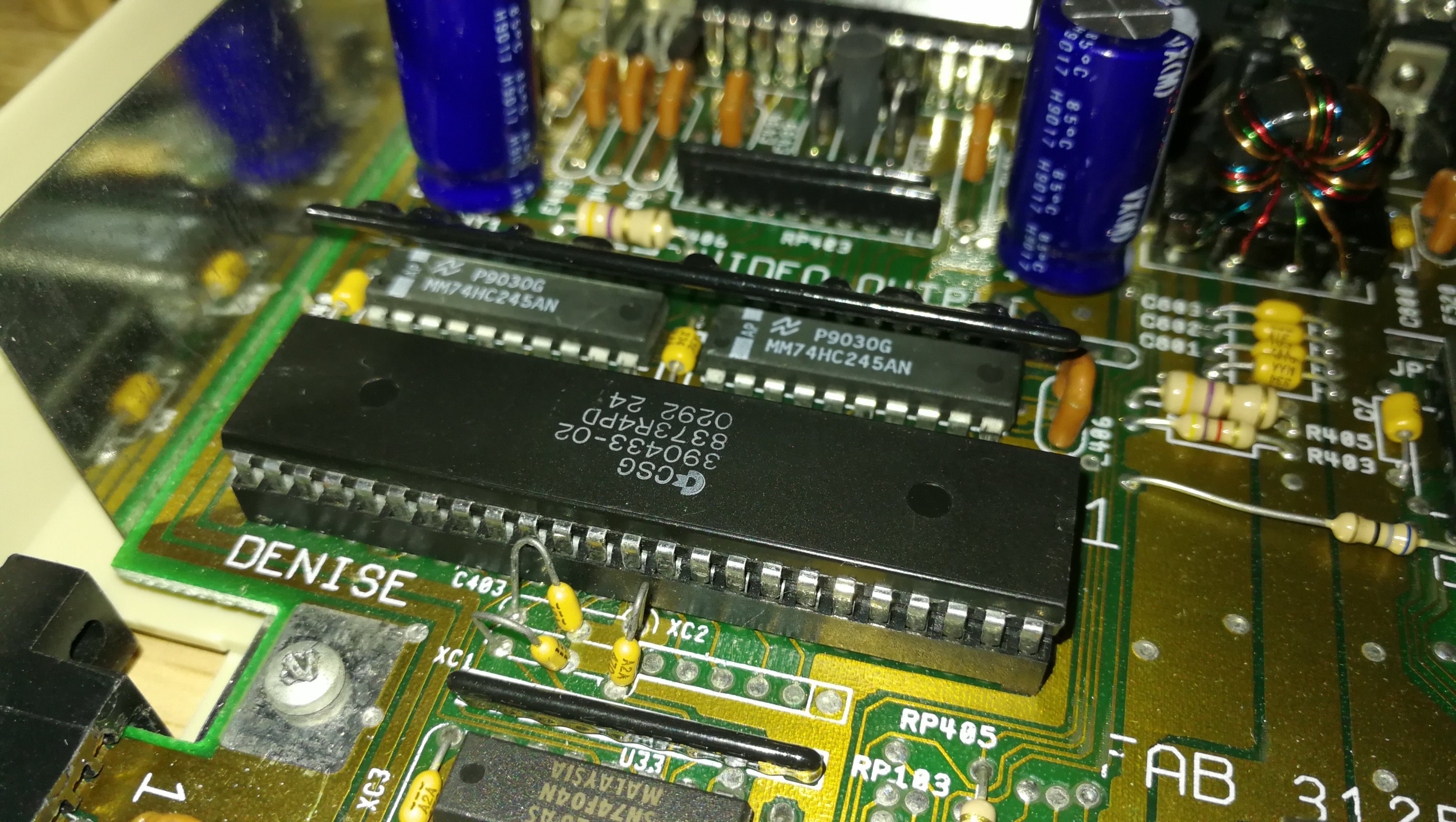
So you may be aware that the Vampire V500 V2+ Card gives your vintage Amiga 500 both a MicroSD card slot and an HDMI port for hooking up to a modern display.  Trouble is the ports are on the board itself which is rather inconvenient if you don’t want to leave the top of your Amiga’s case off.  After doing a little research and searching around I discovered that you can get some nifty little extension cables for both ports which will allow you to ‘move’ them to the exterior of the Amiga’s case.  This post will explain how to add both an SD Card Slot and HDMI port to an Amiga 500 computer.

SD Card Slot and HDMI port to an Amiga 500

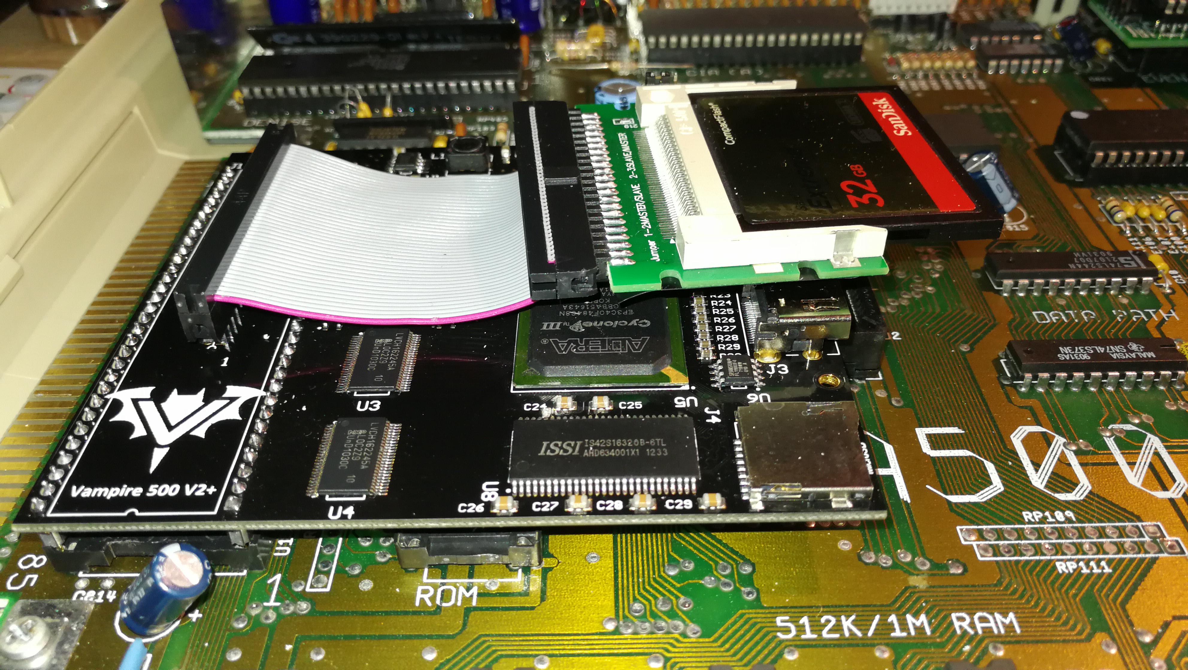
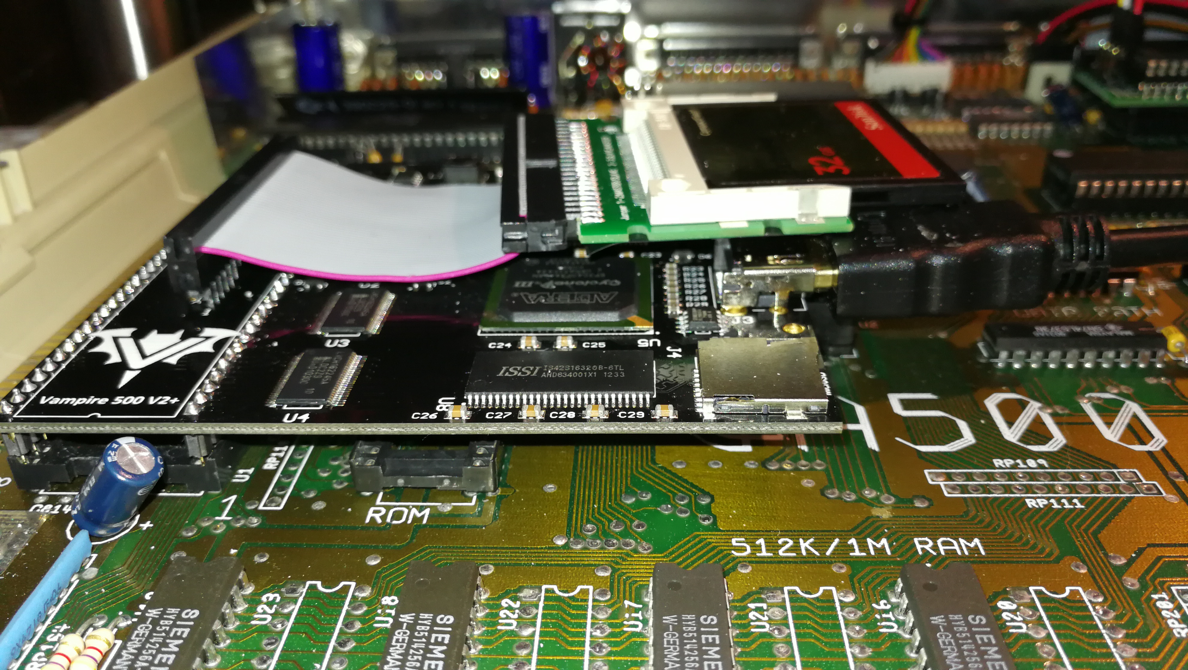
Location of the HDMI and MicroSD ports on the Vampire card. Not exactly easily accessible once the lid is back on!

Purchasing the right cables for the job

The HDMI cable was a little tricky to locate at first as there are just so many options. Once I got the search term correct I stumbled into the right cable for the job.  The cable I bought (below) was an Adafruit Panel mount HDMI Cable – 40 cm which you can pick up from Amazon.  It’s just the perfect length and almost seems tailor made for the Amiga!

SD Card Slot and HDMI port to an Amiga 500

40cm HDMI extension cable

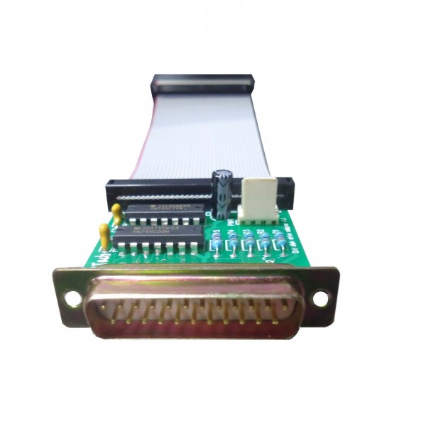
The MicroSD slot extender was a much easier product to locate.  This Micro SD to SD Card Extension Cable I picked up from Amazon is perfect.  You will find that you can actually get both MicroSD to MicroSD and also MicroSD to SD extender cables.  I decided to chose the MicroSD to SD option as I thought it would allow a little extra flexibility in terms of what cards I can use with it.  With it I have a choice of using both regular SD cards or  MicroSD cards now with the use of a MicroSD adapter card.

SD Card Slot and HDMI port to an Amiga 500

MicroSD Extension Cable

Deciding where to locate the ports

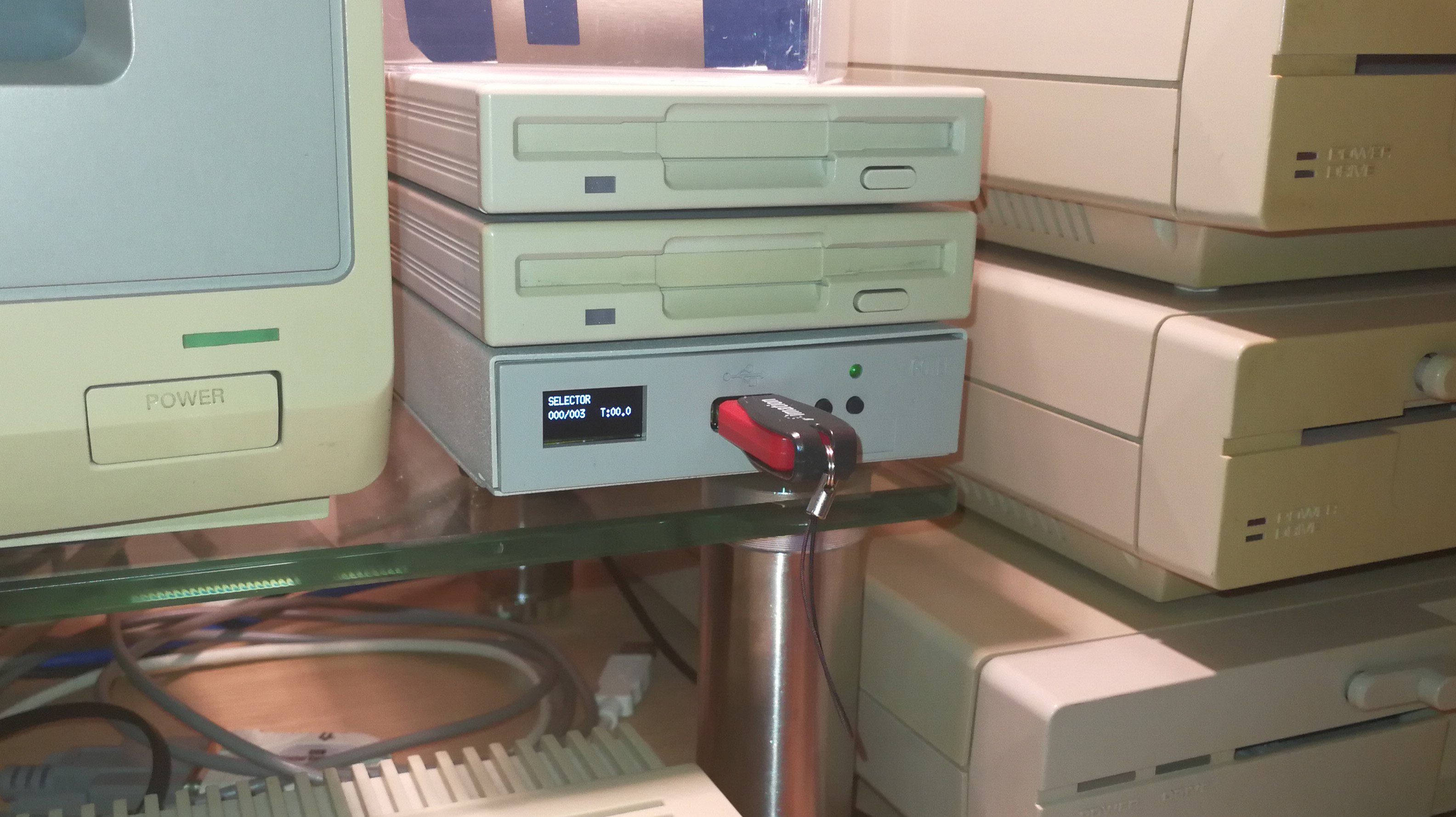
I decided the HDMI port needed to be at the back of my A500 but that the SD card would be much more useful if it was located somewhere along the side.  There is quite a lot of free space underneath the floppy drive, ample to accommodate the HDMI socket.  However because the SD Card Slot is housed in quite a chunky plastic case there wasn’t room for it under the floppy, plus I already have my floppy boot selector switch there anyway.  So, I chose a spot that sits just under the keyboard where there is plenty of space and it’s also super convenient for me to pop cards in and out.

SD Card Slot and HDMI port to an Amiga 500

Final Cable Routes


SD Card Slot and HDMI port to an Amiga 500

HDMI Socket secured with hot glue. It ain’t pretty but it’s very secure.


SD Card Slot and HDMI port to an Amiga 500

Plenty of clearance around floppy drive


SD Card Slot and HDMI port to an Amiga 500

SD Card Slot Hot Glued in position

Creating the SD Card and HDMI cut-outs in the Amiga case and securing the new ports

The slots for both ports were cut out using a Dremel tool (if you have one you should know instinctively how to do this!). Take care to use a low speed otherwise you risk melting the plastic.  The ports themselves are held in place with some hot glue, perfect for this sort of project as it flows freely around things before setting hard.  I used a few blobs of hot glue to keep the SD extension ribbon cable out of harms way too as it’s quite fragile.  It could easily become trapped and get damaged by the A500 keyboard when it is replaced if it was left unchecked.

SD Card Slot and HDMI port to an Amiga 500

Top view of HDMI Socket with floppy drive back in place


SD Card HDMI Amiga

Finished HDMI Port


SD Card HDMI Amiga

Finished SD Card Slot with MicroSD adapter sticking out

End Result

I’m pretty pleased with the end result, with hindsight I probably should have tidied up the HDMI cut-out a little with a file as there are a few rough bits left… but it’s around the back of the case and out of sight so no biggie.  The HDMI port is rock solid and should have no problem with me plugging and unplugging a cable in and out.  Likewise the SD card slot is nice and secure and more than up to the task of dealing with regular card swaps.  Perhaps a version in white (or off-white LOL) would have been better but I just couldn’t find one for sale anywhere.

Improvements?

Only other thing I might do in future is add an RJ45 extender when the Apollo Vampire team make the Ethernet port expansion option a reality.  Although I already have Ethernet through the use of the fantastic little plipbox device this is currently hogging my parallel port so I cannot print without first unplugging it – hardly ideal.

Formatting the SD Card

Incidentally, if you’d like to know how to go about formatting your SD Card check out my post – How to Format an SD Card for Amiga to PC File Transfer.


Fitting an SD Card Slot and HDMI port to an Amiga 500.

Installing the Vampire V500 V2+ in my Amiga 500

Vampire V500 V2+

With the arrival of the weekend it was the perfect time to give my A500 the Vampire V500 V2 treatment!

Getting started – removing chips

First off I needed to remove the original Motorola 68000 CPU and the Kickstart chip.

Vampire V500 V2

Amiga 500 motherboard with empty 68000 CPU socket

Vampire V500 V2

Removing the Kickstart chip with a chip puller

Installing the card

The next step involved carefully inserting the Vampire board connector pins into the empty CPU socket. This actually took a hell of a lot more force than I thought it would. I’ll admit I was scared of damaging the CPU socket or the motherboard itself with the amount of pressure I had to exert. Anyway it eventually slotted in all the way and no harm was done. Please do make sure you remove both the CPU AND the Kickstart chip though – this wasn’t mentioned in my instructions (but they’ve been updated since I got mine to mention this). If you don’t remove the Kickstart chip then the Vampire board won’t sit flat and the CPU connections may be unreliable. Thanks to Igor Majstorovic for taking the time out to let me know about this!

Vampire V500 V2+

Vampire V500 V2+ fitted to A500 CPU socket

Cables & CF Card setup

The next step was to hook up an HDMI cable to the socket on the board and fit a Compact Flash ‘hard drive’ to the Vampire’s 44 pin IDE header. I opted for a 32Gb CF card as this is the size of the Apollo OS (Coffin) image. (This is a pre-configured Workbench 3.9 system that you can download and use with your Vampirised A500.

Imaging the card was simply a matter of downloading the Apollo OS image from here and using Win32 Disk Imager in Windows 10 to write that image to my Compact Flash card.

Vampire V500 V2+

Vampire V500 V2+ with CF Card and HDMI connected up

For once in my life everything went as it should and when I powered up my Amiga 500 it worked! As Hannibal would say; ‘I love it when a plan comes together!’ I was greeted with a really cool Vampire logo boot screen after which the Workbench loaded just a few seconds later.

Vampire V500 V2+

Vampire V500 V2 Boot Screen

Vampire V500 V2+

Vampire V500 V2 ‘Insert Floppy’ Screen that appears if no bootable device is present

My Vampire Card has arrived!

Vampire V500 V2 Card

It’s finally here, after months of waiting, My Vampire V500 V2 Card! Still need to gather a few other bits and pieces before I can fit it but here is a quick look at it in all its’ glory for now.

Vampire V500 V2 Card

Amiga 500 Vampire V500 V2+ Box

Vampire V500 V2 Card

Inside the Vampire box

Vampire V500 V2 Card

Vampire V500 V2+ Card – 44 Pin IDE connector visible on the left

Vampire V500 V2 Card

Vampire V500 V2+ Card Reverse – pins on the right fit into the original 68000 CPU socket.

Vampire V500 V2 Card

Vampire V500 V2+ Card Ports: MicroSD on the left, HDMI, JTAG programming port, I/O Expansion port just behind and to the right.

Fitting an External, Boot – selectable Gotek Drive to an A500

Amiga Gotek External Cable

I wanted to avoid having to have one of these hanging off the back of my A500.

I wouldn’t really call this an upgrade as such, more taking advantage of the latest developments in the Amiga scene. In case you’ve never heard of it, the ‘Gotek’ drive is basically a 3.5″ Floppy Drive emulator. Instead of putting floppy disks in it you plug in a USB flash drive that can contain up to a thousands Amiga Disk Files or ‘ADF’s’ (floppy disk images).

There are quite a few versions of these floating around on eBay, internal and external. I decided pretty early on that I wanted mine external so I could keep my A500’s DF0 as a real floppy drive so I opted for an external drive. I wanted to have the install look as authentic and neat as possible so I opted to install my Gotek inside an old external floppy disk drive that I picked up off eBay for spares/repairs. If you want to do the same just be careful to pick one that houses a regular sized floppy drive and not a reduced height, slim one as the Gotek won’t fit. You can see what I mean from the photo below which shows my finished Gotek drive underneath a couple of Roctec slim drives – it should be pretty obvious that the slim drives don’t have the necessary height to accommodate the Gotek drive.

The other choices available now include the option to have an OLED screen that can display the name of the ADF file you select and the track info and also a built in speaker that can simulate the noises of the real thing. It’s more of a buzzer than anything else but it’s pretty effective and much better than sitting in silence waiting for Cannon Fodder to load!

Finished Gotek Drive

Finished Gotek Drive under my two Roctec slim external floppy drives

Close-up of Gotek Drive with OLED Screen

Close-up of Gotek Drive with OLED Screen

Boot Selector Installed in Even CIA Socket

Boot Selector Installed in Even CIA Socket

Mounting of Selector Switch

Mounting of Selector Switch

DF0 / DF1 selector switch

DF0 / DF1 selector switch

Sam’s Journey

Sam's Journey

Ordered Sam’s Journey months ago and it finally arrived today. A brand new cartridge game in 2018 for the Commodore 64! Presentation of the box and its’ contents is fantastic – can’t wait to play it!

If you would like to get hold of a copy yourself then you can buy it here.


Sam's Journey

Sam’s Journey


Sam's Journey Box Back

Sam’s Journey Box Back


Sam's Journey Inside the Box

Sam’s Journey Inside the Box


Amiga 500 Super Denise Upgrade

The A500 machines shipped with a graphics chip called ‘Denise’ that is responsible for handling sprites and also all the different screen modes and resolutions you can use with Workbench and other apps. The later Amiga 500+ model sported an updated chip called ‘Super Denise’ which offered quite a few more screen modes and resolution options. The Amiga 500 Super Denise upgrade is a very straightforward modification which simply involves getting hold of the newer chip and replacing the old one with it. (It is an exact pin-for-pin replacement). For more detailed info on the Denise chip look here.

Getting hold of a new chip

The ‘Super Denise’ has the chip number 8373-R4 whereas the old regular ‘Denise’ is 8362. You can usually pick up Super Denise chips on eBay – here.  I paid around £20 for mine which I though was fair… be patient and wait for one at a fair price – don’t get ripped off.

Removal & Replacement of the chips

You can remove the the old chip with just a small flat bladed screwdriver if you are careful. Just lever up each end slowly, alternating from one end to the other, making sure it lifts evenly from each corner so that the pins don’t bend. Ideally though, use an ‘IC Extractor’ – it makes the job a lot easier and is a useful tool to have in your retro computer toolkit anyway. Again these are readily and cheaply available on eBay – here. The new chip should just plug straight into the socket. Make sure the marked end of the chip matches up with the notched end of the IC socket. If it goes in the wrong way around it won’t work and may even damage the chip and/or the motherboard. If the pins don’t quite line up you can bend them gently into place using a pair of pliers.

Amiga 500 Super Denise Upgrade – In Pictures

Below you can see before and after screens showing SysInfo details, and available screenmodes along with the two different Denise chips fitted. The end result is a success with more screenmodes (eg Super-Hi Res modes) available straight away, even with my standard 1084S monitor. However in order to benefit from the rest of the modes the Super Denise chip offers (such as Productivity) I need to get hold of a proper Multi-Sync monitor that can handle the different refresh rates they need.

Amiga 500 Super Denise Upgrade

Sysinfo Screen with Standard Denise Fitted

Amiga 500 Super Denise Upgrade

Screen Modes Available with Standard Denise Chip

Amiga 500 Super Denise Upgrade

Standard 8362R8 Denise Chip Fitted

Amiga 500 Super Denise Upgrade

Replacement 8373R4 Super Denise Chip Fitted

Amiga 500 Super Denise Upgrade

Sysinfo Screen with Super Denise Fitted

Amiga 500 Super Denise Upgrade

Screen Modes available after fitting Super Denise Chip

Repairing a Roctec Floppy Drive for an Amiga

Repairing a Roctec floppy drive

This is a guide to repairing a Roctec floppy drive for an Amiga 500 computer.  I thought I’d write this up as much for my own benefit as other peoples so I can refer back to it in another 20 years! LOL.

Roctec Amiga external floppy drive

Roctec Amiga external floppy drive

If you ever pop a disk in your external Roctec drive and hear a strange whirring noise and can’t read any of your disks then the chances are you are suffering from a perished or broken drive belt.

Perished Drive Belt

Perished Drive Belt

These drives use a rubber belt to connect the drive motor to the spindle hub. The rubber belt only has a finite life and given most of these drives are getting on for 30 years old now it’s hardly surprising that they expire.

cof

No tension in old perished belt

The good news is that it’s pretty easy to replace them and I’ll give an overview of what you need to do here.

Getting Started on the Repair

The first thing you need to do is undo the 6 screws on the underside of the drive case using a small philips screwdriver.

Underside of drive case

Remove these 6 phillips screws.

This particular drive case is made from a solid metal rectangular tube so you need to slide the floppy drive out. The aim here is to slide everything out of the BACK of the case. The first step is to gently slide the floppy drive forward out of the case far enough to detach the plastic fascia from the front of it. Unless you do this it won’t slide right into the case and out the back. There are 2 small tabs on each side of the fascia which you can gently bend with a small flat-bladed screwdriver and it will pop right off. Don’t force anything or it will break – it should come off easily.

Drive Fascia removed

Drive Fascia removed

Now you need to prise the back part of the drive out of the case using something thin enough to slide into the tiny gap between the case and the backplate, I found the blade of my pocket knife to be perfect for this but be careful not to injure yourself or damage the plastic/paint on your drive! Once you’ve got it moving slide it out slowly (a slight side to side wiggle can help here). It will be attached to the floppy drive via a ribbon cable so keep going until you’ve got the floppy drive out too.

Roctec floppy drive detached

Roctec floppy drive detached from controller board

The floppy drive has a thin metal cover that protects the mechanical innards and it is held in place by some little tabs on the edges and a solitary screw at the back right (when viewed from the front).

Roctec Floppy Drive Rubber Belt Path

Roctec Floppy Drive Rubber Belt Path

Replacing the Belt

Once the top is off you can see the drive mechanism, motors, heads and so on. Carefully remove what’s left of the old belt with a pair of tweezers. Be careful not to touch the drive heads with anything metallic or you may damage them. The photo above shows the path the rubber belt follows, indicated by the yellow line.

The next step is to remove the drive motor which is attached to a metal bracket that runs across the back of the drive. It is held in position by one screw in the far left corner and another on the right a few cm down from the corner. Don’t touch the two screws with the large flat heads either side of the motor. Be careful you don’t pull the bracket too much as there are two tiny wires connecting the motor to the circuit board here so be careful to support the bracket whilst you are handling the drive to replace the belt.

How to detach the motor and bracket

How to detach the motor and bracket

Drive motor and bracket removed

Drive motor and bracket removed

Once the bracket and motor are out of the way you can carefully thread a replacement belt around the large drive wheel, small tension wheel and keep a loop ready at the top right to go on the motor spindle. Follow the yellow path in the earlier photo and take your time as it can be a little tricky to get the belt into place. A small flat bladed screwdriver and a pair of tweezers are essential for this. Don’t forget the belt needs to thread behind the small silver pully wheel as this is what tensions the belt.

Close-up of the small tension wheel you need to thread the belt behind

Close-up of the small tension wheel you need to thread the belt behind

Once you’ve got it threaded around the wheels correctly you need to get the final loop onto the motor spindle. It helps if you grab the loop with some needle nosed pliers here and pull it taught with one hand whilst guiding the motor spindle into the loop with the other. Once this has been achieved (it may take a few goes as it’s quite fiddly) place the bracket back in place and rotate the large drive wheel slowly and check the belt stays on, is running where it should and isn’t fouling any components.

Look carefully through the tiny gaps in the top of the drive motor you should be able to see the motor armature slowly rotating as you move the belt. If it is then job  done, time to put it all back together! If it isn’t then don’t fret, just double check the belt is following the correct path, isn’t twisted anywhere and hasn’t slipped off any of the wheels.

Congratulations, your Roctec drive should now be fit for active duty for another several years now!