After getting it online this has to be the next best thing your can do with your Amiga. Being able to access a network share on the Amiga is really a liberating experience. It affords you not just the freedom to quickly access files you may have downloaded on your PC but also near unlimited extra storage for your Amiga. It’s quite a straightforward process and I’ll go through the whole thing from start to finish in this post.
Before going any further it’s assumed that you already have your Amiga networked and have configured a TCP/IP Stack as these are essential. You will also need a Windows based PC to create a shared folder on (or a suitable NAS that supports the SMB1).
Installing the Amiga Software
I’ll deal with the Amiga installation side of things first as that’s much more straightforward. To begin with you need to download two packages off Aminet, smbfs-68k.lha and SMBMounter.lha.
We only need a single file from the SMBFS package so simply extract the LHA archive to your RAM disk and then copy the ‘SMBFS’ file to your C: drive. (Strictly speaking if you are comfortable with the command line then this is all you need but we’re going to install a GUI for it, hence the need for SMBMounter).
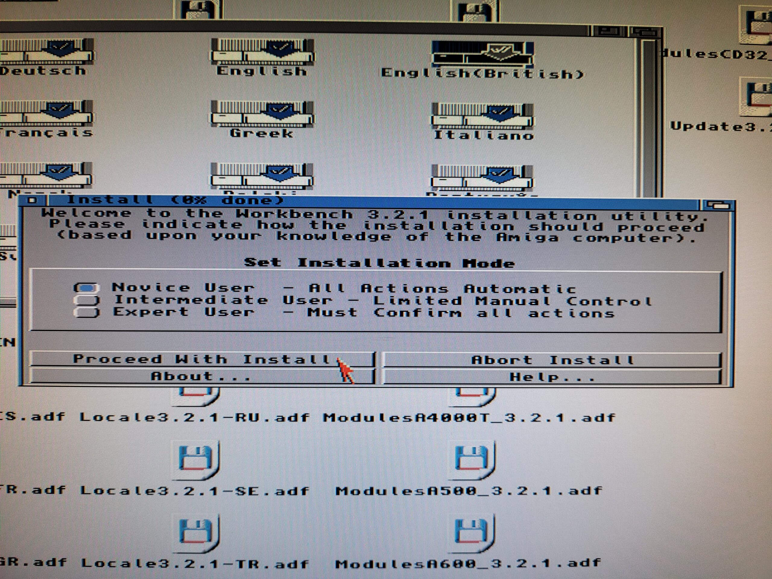
Next extract the SMBMounter archive, run the installer and select ‘Intermediate User’ as shown below.
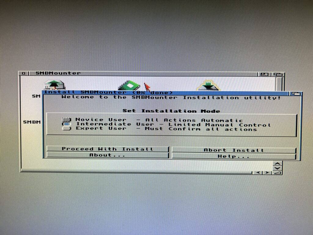
Installing SMBMounter
Select ‘Install for real’.
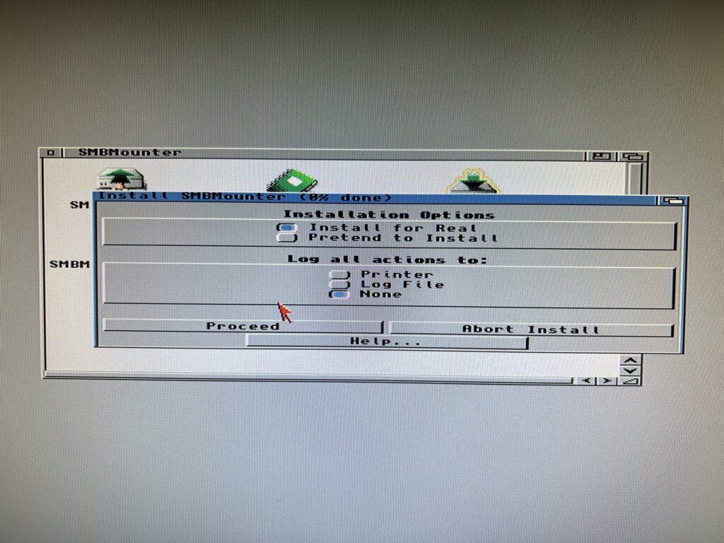
Installing SMBMounter
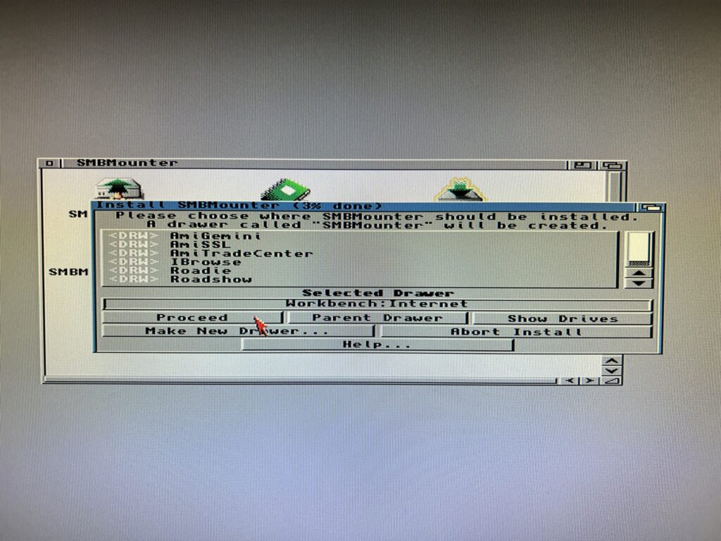
Choose where to install the software. It doesn’t really matter but in my case I selected my ‘Internet’ drawer as I like to keep all my internet/network related stuff in one place. Note that you do not need to create an SMBMounter drawer – one will be created automatically in the location you choose.
Installing SMBMounter
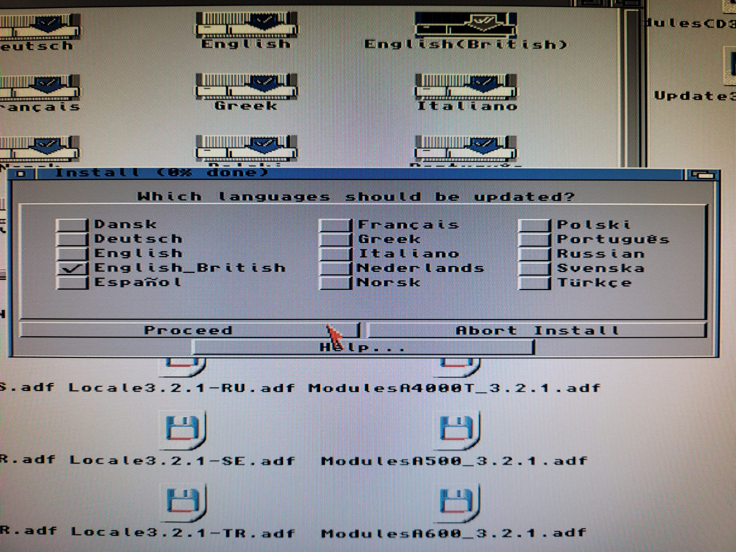
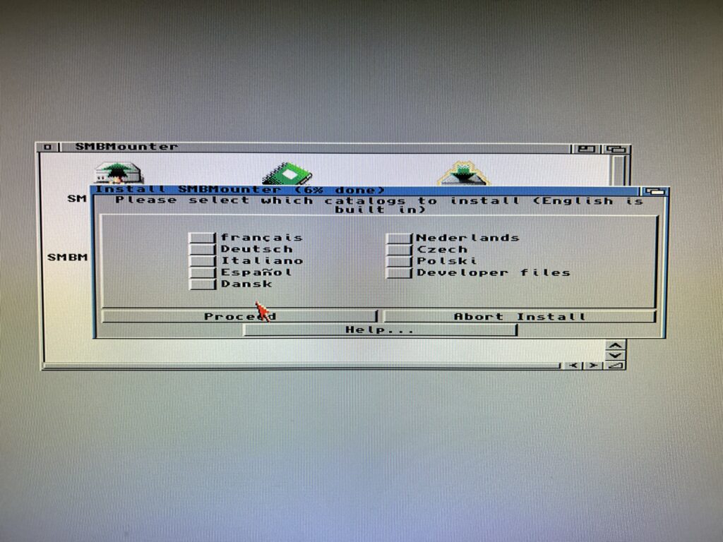
Next choose a language if English is not your native tongue.
Installing SMBMounter
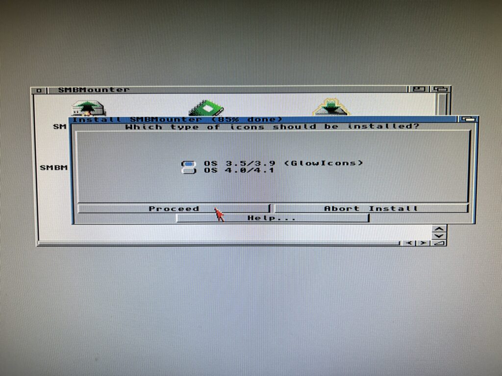
The final thing to choose is the icon set that will be used for the program files. I’m using OS3.2 and like GlowIcons so chose that option.
Installing SMBMounter
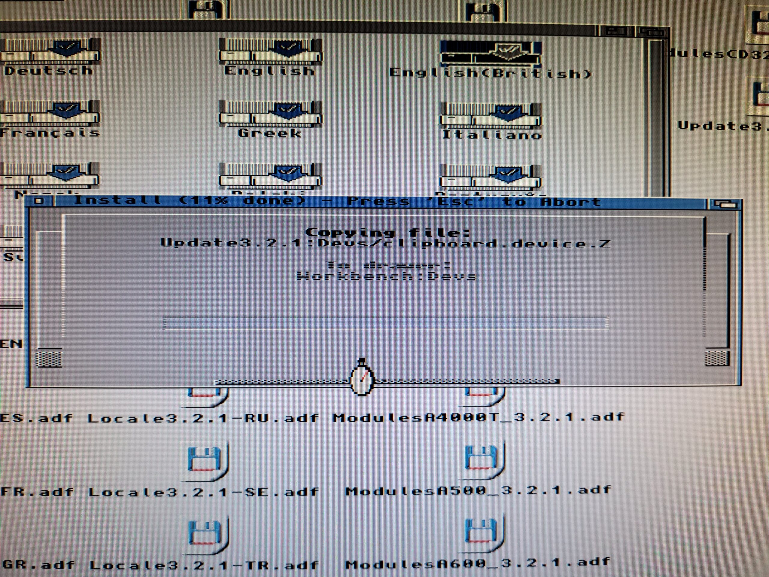
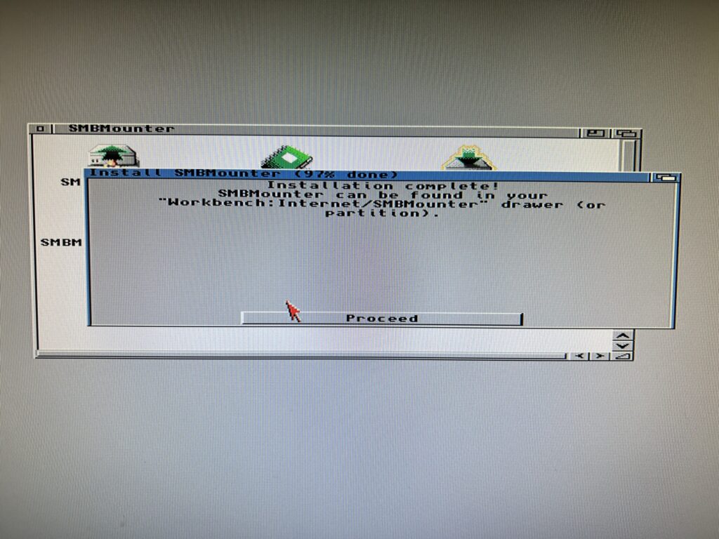
The program will now be installed. After a few seconds you should get an ‘Installation Complete’ message along with a reminder of the install location.
Installing SMBMounter
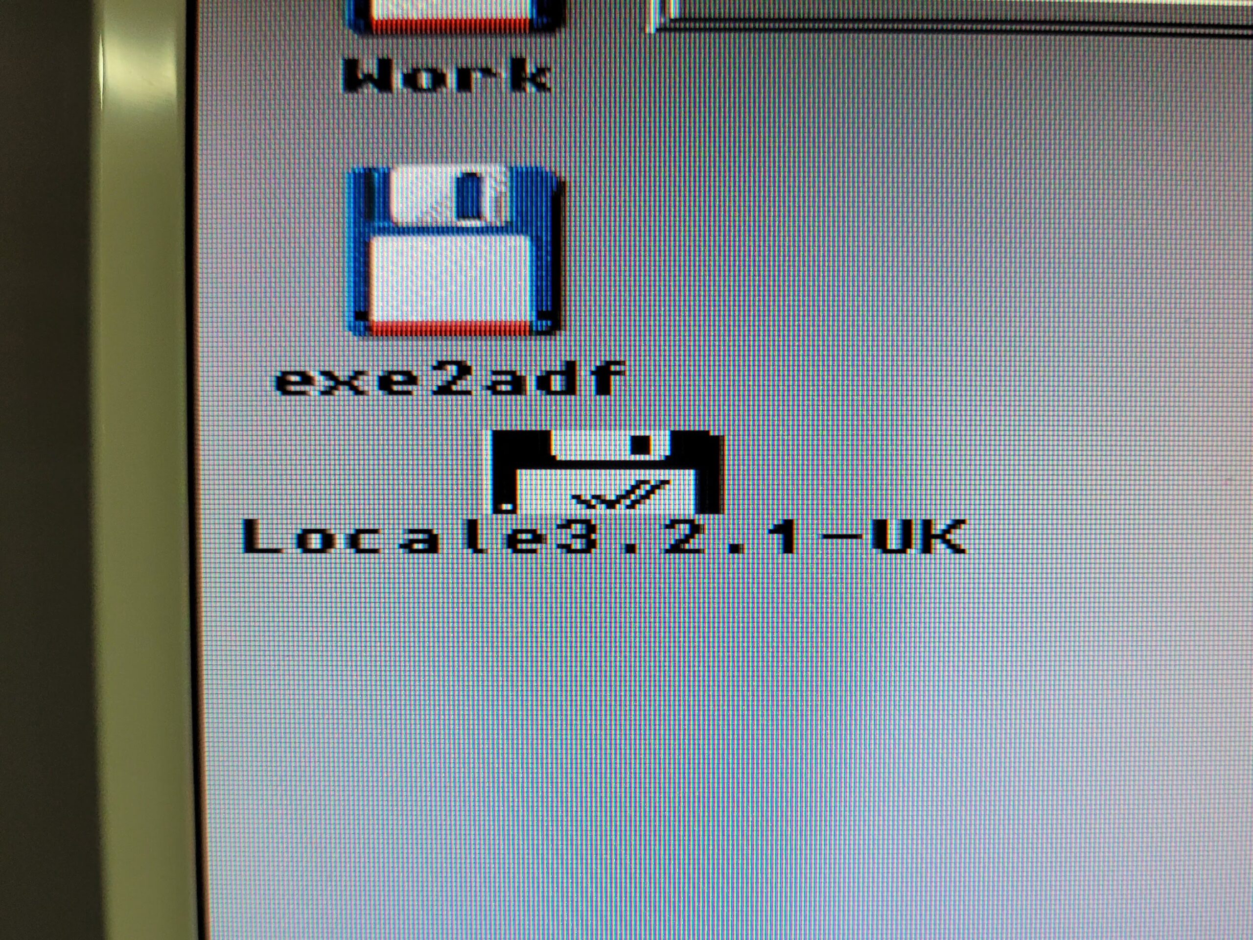
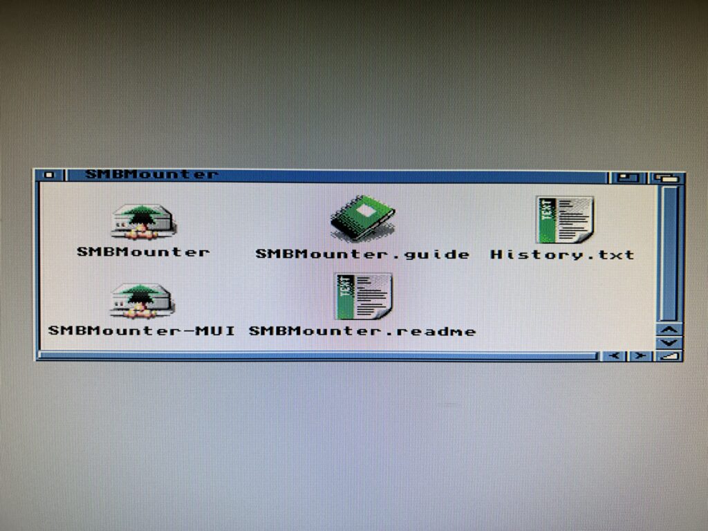
If everything went well you should have a drawer looking just like the one in the photo below.
Installing SMBMounter
That’s it for the Amiga side of things, at least for now anyway. Time to boot up your Windows PC and configure something for the Amiga to connect to!
Configuring an SMB1 Share on a PC
Enabling SMB1
I just want to preface this section by saying that I created this guide on a Windows 11 PC (which was upgraded from a Windows 10 install). It should work with older versions of Windows too. However Microsoft is actively trying to kill off SMB1 (see here) so if you are reading this in the future you may have a few extra hoops you need to jump through to get this working. (Alternatively just use an old PC running Windows 10!)
Right, with that out of the way the first thing you must do is determine whether your PC has SMB1 file sharing enabled, and if not, enable it. The easiest way to achieve this is to open the ‘Turn Windows features on or off’ control panel.
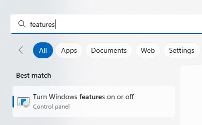
Turn Windows Features on or off
To do this use the start menu search facility and type ‘features’. Windows will have a rummage around the C: drive and then present you with the program so you can just click on it as shown above.

Checking that SMB1 client/server is enabled.
Scroll down the list until you get to the SMB section. You want to see little check boxes next to ‘SMB 1.0/CIFS Client’ and ‘SMB 1.0/CIFS Server’. If they aren’t ticked, click in the little boxes to enable them and then click on OK. You will have to restart Windows for it to complete the installation of the new features.
Please note you do NOT want to have a check mark next to ‘SMB 1.0/CIFS Automatic Removal’. If you do have it ticked this will cause Windows to remove SMB after a few weeks of the protocol not being utilised.
Creating a Local User Account
This part isn’t strictly necessary but I recommend it as it helps keep things neat and tidy and also prevents issues in the future should you change your PC account password. I’m doing this in Windows 11 Home. There are multiple ways to achieve this but I’m just going to describe one method which is very straightforward. If you already know how to do this then skip to the next section.
Firstly using the start menu search enter ”netplwiz’ and then run the program that Windows finds.
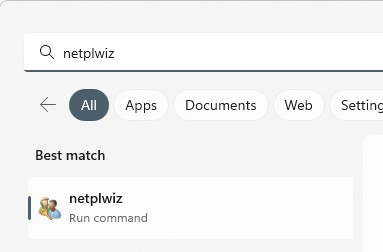
Running NETPLWIZ to access user accounts.
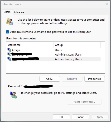
This will bring up the ‘User Accounts’ window. You should see at least one account here which will be your main Windows account. There may be others too, depending on how many people use the PC.
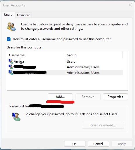
Windows 11 Local User Accounts window.
I had already created an Amiga account when I took the above screengrab but will pretend I didn’t for the rest of this section so click on ‘Add…’ to continue.
No I don’t want to create another Microsoft account…
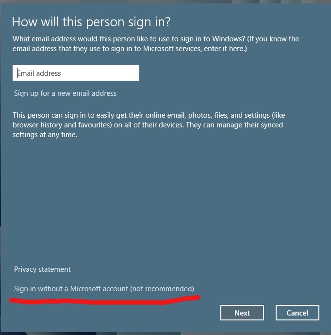
Ignore Microsoft’s recommendation and click on the bit at the bottom which says ‘Sign in without a Microsoft account (not recommended) and then click ‘Next’.
I just told you I don’t want one, take the hint!
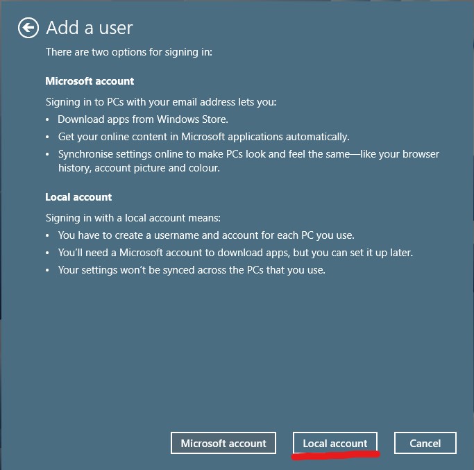
Select the ‘Local account’ option from the bottom of the next window that appears…
Microsoft finally took the hint and let me set up a local account.
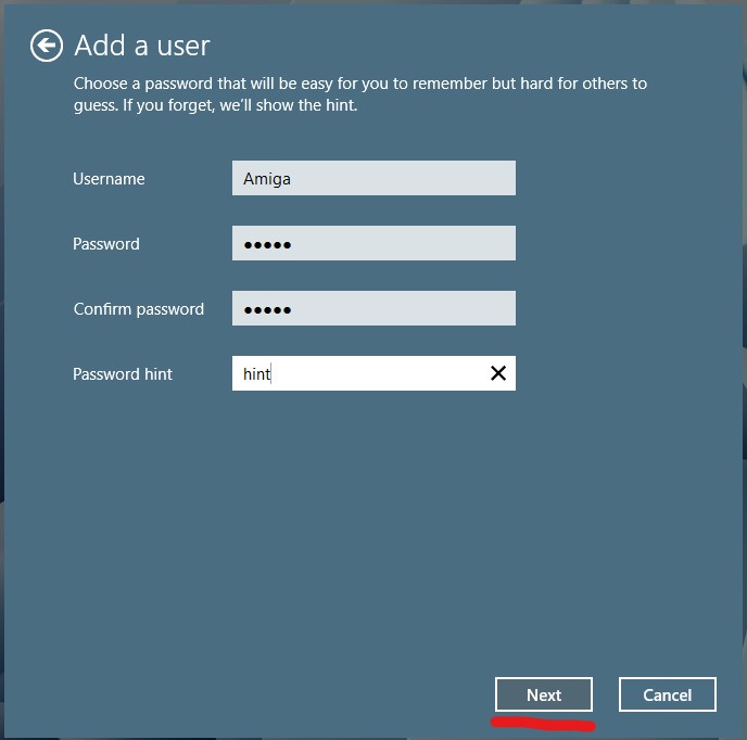
Enter the name for your local account, ‘Amiga’ in my case, a password (twice) and a Password hint in case you forget it (this can’t be skipped unfortunately). Click on ‘Next’ when ready.
One local Amiga account all ready to go.
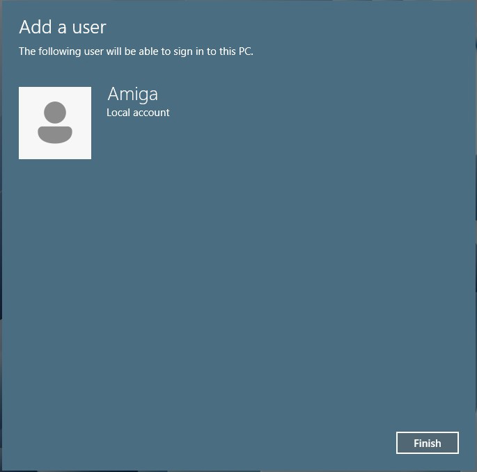
This will bring up a confirmation screen with the name of your account. Click ‘Finish’.
Mission accomplished.
This will bring you back to the User Account window (above) which you can now safely close by clicking on ‘OK’. Your local account is now created and ready to be used in the next section.
Creating a Shared Folder
With SMB1 enabled it’s now time to setup a shared folder that your Amiga can actually connect to. Choose a location with enough free space on your PC and create a new folder there. I chose my E: drive as it has plenty of free space but you can choose any location you want. Give it a suitable name.
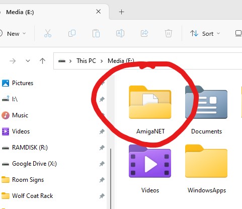
Creating a folder for our share.
Now we need to SHARE this folder so right-click on it and select ‘Properties’ and then ‘Advanced Sharing…’
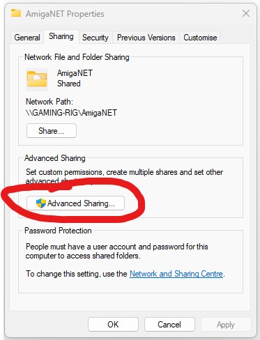
Selecting Advanced Sharing
Once the Advanced Sharing windows pops up you need to tick the box next to where it says ‘Share this folder’ and then give the share a name in the box below. Try to keep the name short and without spaces or punctuation to avoid any problems connecting to it down the line.
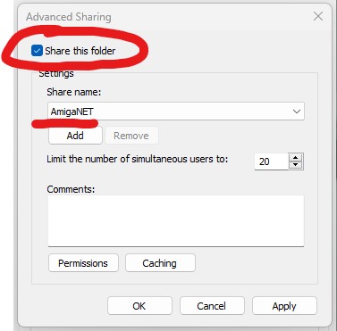
Enabling sharing and giving the share a name.
Before closing the Advanced Sharing window, click on the ‘Permissions’ button near the bottom.
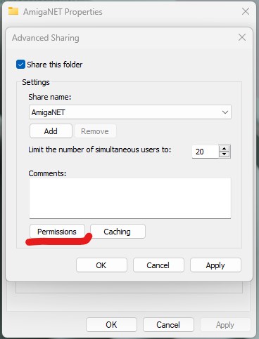
Click permissions.
A new window will pop up allowing you add a new user to access the shared folder. To do this click on ‘Add’.
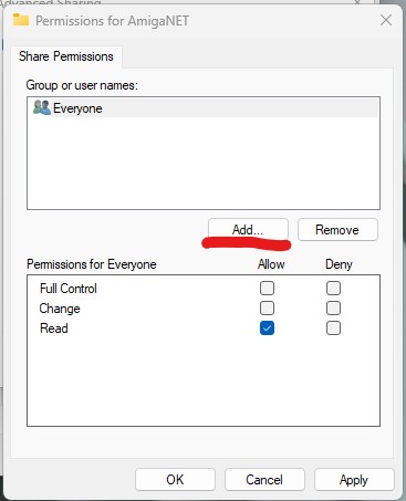
Click Add.
The will bring up yet another window where you can enter the account name of the user you want to access the share.
Enter the username into the box. My local user account was called ‘Amiga’ so I entered ‘Amiga’ in this box. You can click the ‘Check Names’ button on the right to make sure you have done this correctly. If you’ve made a mistake Windows will say ‘name not found’ which means it cannot find an account with that name. Time to check your spelling! Click on OK when done.
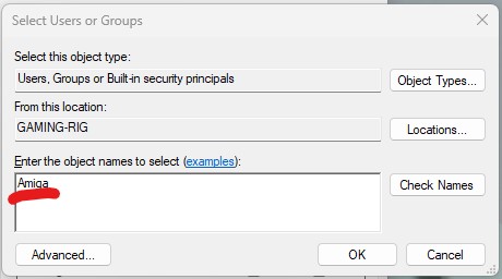
Add YOUR local user account name.
You will be back looking at the Share Permission window again now and you should see the username of the account you just added at the top of the list (see below). Make sure it is selected and then click the empty box next to ‘Full Control’ to grant your Amiga this permission, then click ‘Apply’ then ‘OK’..
By the way, if you are not aware of the name of your computer, you will see it here. It’s the name in the brackets before the backslash (GAMING-RIG in my case) – jot it down as you will need it later!
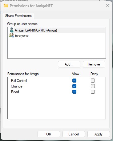
Giving your local account full control of the share.
You should end up with a window looking like the one above. Click OK when you are happy everything looks correct and then on OK once more to get back to the main properties window as shown below. Were are nearly there now – just one last thing to do.
Click on the ‘Security’ tab (highlighted below).
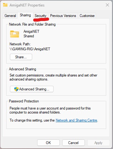
Select the Security tab.
Next click on the ‘Edit’ button…
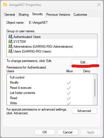
Click Edit.
Then click on the ‘Add’ button…
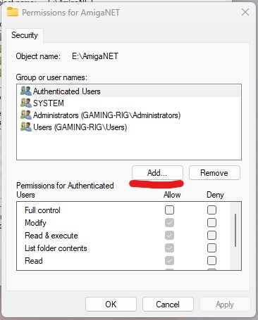
Click Add.
Then just as you did before, enter the same local account username into the box so we can define the permissions this user should have. Once done, click on OK.
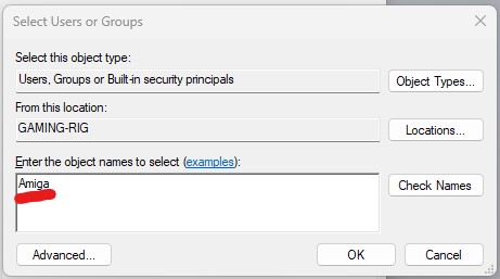
Enter YOUR local account name once more.
Back in the Permissions window make sure that the user is highlighted in the top section and then click on the box next to ‘Full Control’ to grant them full access to the share.
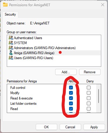
Ensure all the boxes are ticked.
Click on OK and then OK again. Congratulations, you have just created a shared folder on your PC and granted access to it from the local user account you created earlier. Time to get back to the Amiga!
Connecting to the Shared Folder from your Amiga
With the share created, a local account setup, SMBFS installed to C: and SMBMounter installed on your Amiga we are ready for the final piece of the puzzle; configuring SMBMounter.
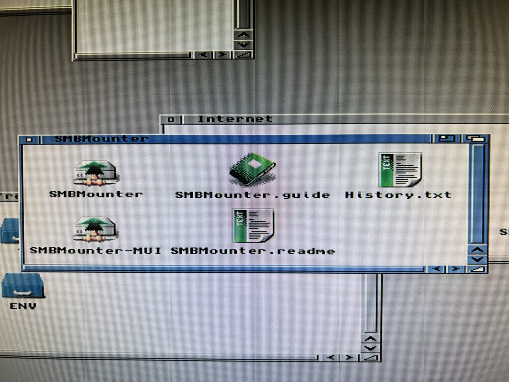
Note the two different versions of SMBMounter (with and without MUI).
There are actually two versions of SMBMounter included, a regular one and one that utilises MUI. They both perform exactly the same functions but I prefer the layout of the MUI version so that’s what I’ll be using here.
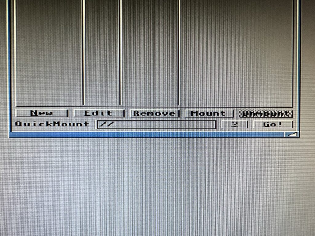
Use the ‘Remove’ button shown above to get rid of the supplied mount entries.
The program comes with a few mounts already configured but they are years out of date and no longer work so delete all of them before going any further to keep things neat and tidy. To delete them simply highlight each one in turn and click on the ‘Remove’ button (see photo above).
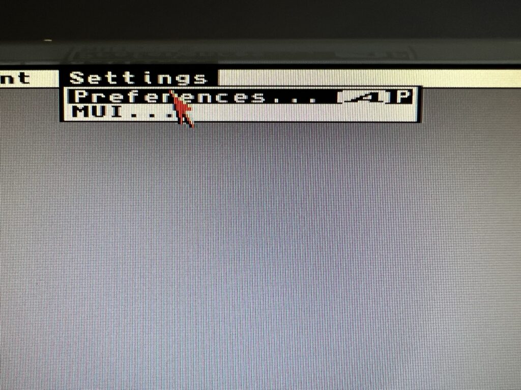
Preferences menu.
Next, open up the Preferences window (accessible from the menu – shown above) to configure a few parameters.
We haven’t bothered installing Samba but to prevent it from complaining I set the path here for it to ‘C:’. The path to SMBFS should be set to ‘C:smbfs’. Note you can browse to the location using the file browser icon on the right of each box if you prefer.
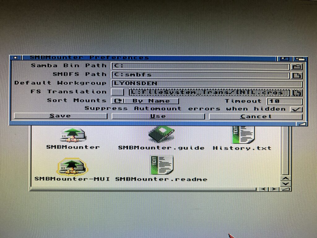
Editing the preferences.
The default workgroup is actually set to ‘WORKGROUP’ and you can probably leave it as is. However I do actually have a workgroup configured on my network so I entered the name of it here; ‘LYONSDEN’. The rest of the settings can be left alone. Double check you have entered everything correctly and then click on ‘Save’ to have it remember your settings and move on.
Entering the settings for our share.
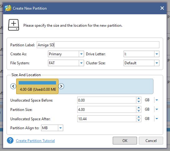
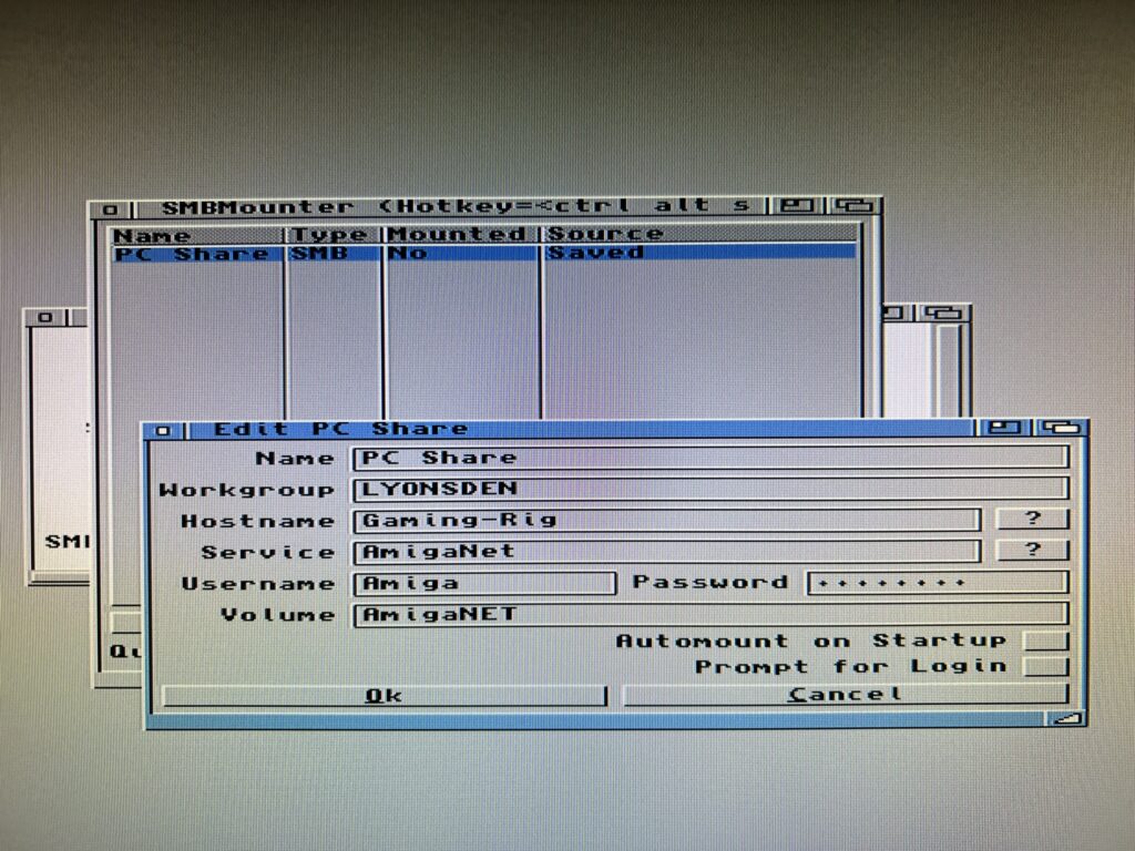
The final hurdle is to configure the connection to our shared folder. Click on ‘New’ and then enter the details of your share using the guidance below to help you.
SMBMounter Configuration
- Name – this is an arbitrary label for the connection as it will appear in the SMBMounter list. (Like the connections it came with when you first installed it for example). I called mine ‘PC Share’ but you can call yours anything you want..
- Workgroup – this will default to WORKGROUP and you can leave it like this but I entered the name of my own workgroup; ‘LYONSDEN’.
- Hostname – this is the name of your PC, in my case ‘Gaming-Rig’. If you are unsure what it is refer back to the section in red where I told you to make a note of it during the ‘Creating a Shared Folder’ section.
- Service – this is the name of the shared folder we created earlier, in my case ‘AmigaNet’.
- Username – this is the name of the local user account we created earlier, in my case ‘Amiga’.
- Password – the password we set for the local user account earlier.
- Volume – this is the name you want the share to have on your Amiga. This is like naming your hard drives when you use HDToolbox. Whatever name you enter here is the name that will appear on workbench when the drive is mounted.
- Automount at Start-up – self explanatory really. I leave this off as I don’t always want the share connected, especially if I just want to play some WHDLoad games for example.
- Prompt for Login – this is an alternative to having the username and password stored and entered automatically. If ticked it will ask you to login with a username and password every time you want to connect. I leave this feature off as it’s would be a pain for me to do this all the time.
Once you’ve entered all the above details and checked they are all correct click on OK. Be sure to ‘Save all mounts’ from the Project menu before proceeding so you don’t lose all those settings when rebooting your Amiga.
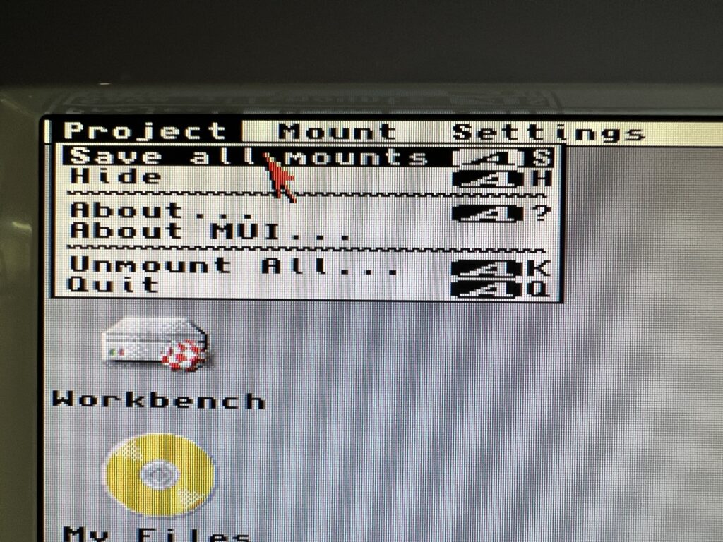
Saving your mount settings.
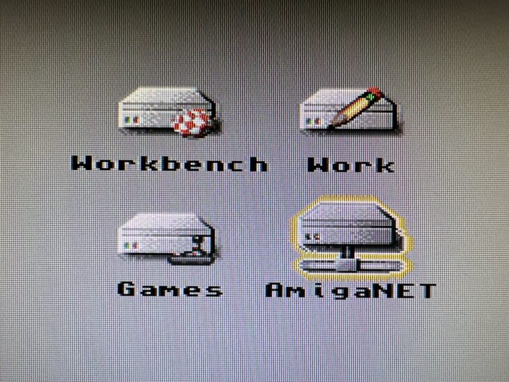
Now for the moment of truth! Click on the ‘Mount’ button in SMBMounter and if you’ve done everything correctly the share should appear on your Workbench after a couple of seconds. (Note – the icon that appears for you will differ depending on what icon packs and settings you are using).
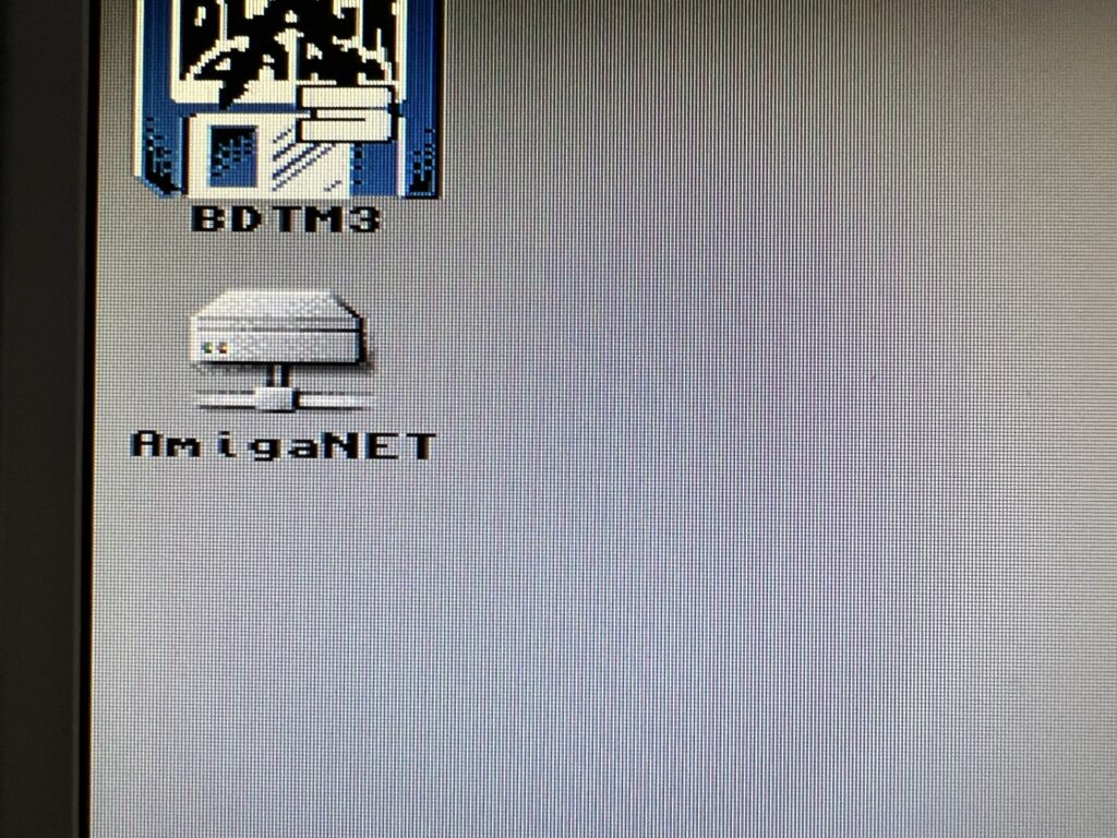
Success – an icon like this on your Workbench means your share is connected!
You can use this drive just like you would any other. Drag and drop files into it, off it, delete them, save stuff there, even change the drive icon. It’s accessible from other programs just like a regular Amiga partition too so you can use it in Directory Opus, Wordworth or whatever other stuff you use.
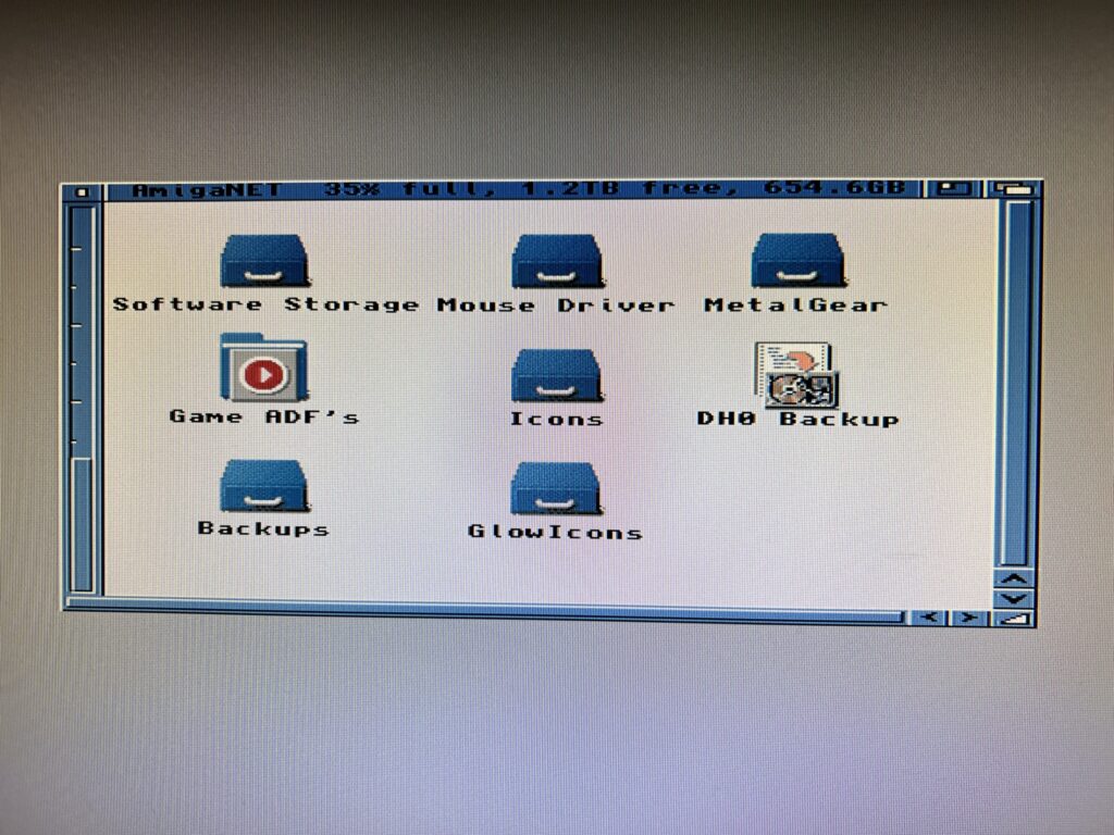
My SMB Share – 1.2Tb free!
As can be seen in the image above the Amiga is able to recognise the full capacity of the shared folder, that’s 1.2 Terabytes in my case – an insane amount of storage for any Amiga.
Quick Troubleshooting Tips
If you get any errors, such as ‘access denied’ or ‘incorrect username/password’ you will need to double check that you have entered the correct and IDENTICAL username and password in both SMBMounter and Windows. Likewise you might need to double check the name of the share in each and so on.
If you’ve done all that find that you cannot connect at all, or if one day in the future it all stops working then your firewall may well be to blame…
Firewalls
A real quick way to prove whether your firewall is at fault is to just disable it and try to connect again. If it works then you have found the problem – if not then at least you’ve ruled something out. Make sure you turn it back on after testing though!
Assuming your firewall is to blame, to fix the problem you are going to need to find a way to allow traffic to flow between your Amiga and PC. I’m afraid there’s no single magic bullet for this – there’s too many variables at play. All I can do is explain how I got around this problem myself. Networking is a pretty complex topic and well beyond the scope of this post to explain everything.
Anyway I use Norton 360 which has it’s own firewall (by default Windows 10/11 use Windows Defender) and it decided to block my Amiga from accessing my share after my Internet went down and my router rebooted. I couldn’t even ping my PC from my Amiga so I knew something wasn’t right.

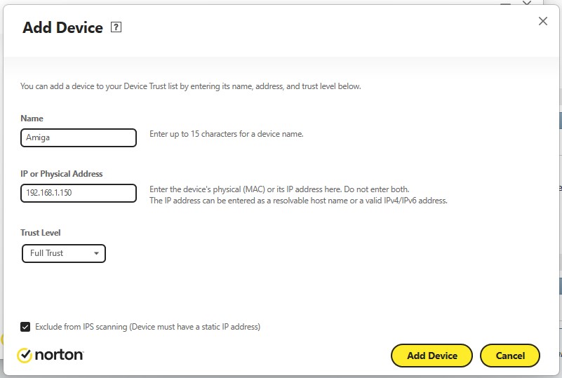
Adding a trusted device in Norton 360’s Firewall settings.
Norton 360’s firewall allows you to add trusted devices that are allowed to connect to your PC irrespective of any other rules that may exist. To do this you must enter either the IP address of your Amiga or the MAC address of the network card you are using in it. This is probably the best method for most users as the MAC address of the card will never change and it is easy to find. Most cards will have their MAC address displayed on a label affixed to them somewhere. Finding out your Amiga’s IP address is not always so straightforward and unless you possess the knowledge of how to make it static you are going to keep having this issue over and over. Why? Because the IP will change frequently and your firewall will no longer know it should be trusted.
Adding a trusted device in Norton 360’s Firewall settings.
As I knew what my Amiga’s IP was (using the Roadie GUI for Roadshow) and I knew how to make IP reservations on my router (so my Amiga always gets the same IP) I used the IP address to configure my firewall as shown above.
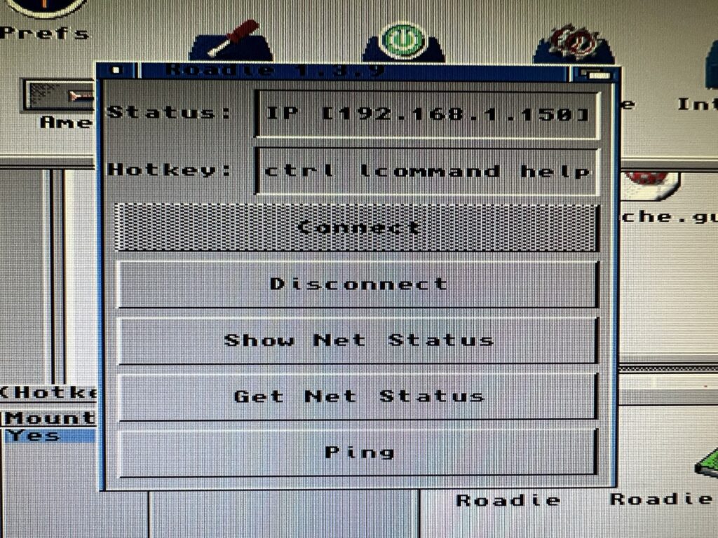
Using Roadie to find out my Amiga’s IP address.
After adding my Amiga as a trusted device I was able to ping my PC and connect to the share immediately.
If you too are experiencing firewall issues then hopefully my experience has given you enough pointers to sort them out for yourself. You might have to do some Googling but at least you should have an idea of what to search for!
Transfer Speeds & Conclusion
Transfer speeds are not as fast as the internal Compact Flash HD using the SCSI.device interface. I timed a few different file transfer operations to give some practical examples. A 3.5Mb LHA archive file copied from DH0: to DH1: took 6 seconds to transfer. It took the same time to transfer to my RAM Disk. That exact same file took 49 seconds to transfer to the SMB shared folder across the network. This is to be expected though – my A1200 is using a really old 10Base-T network card.
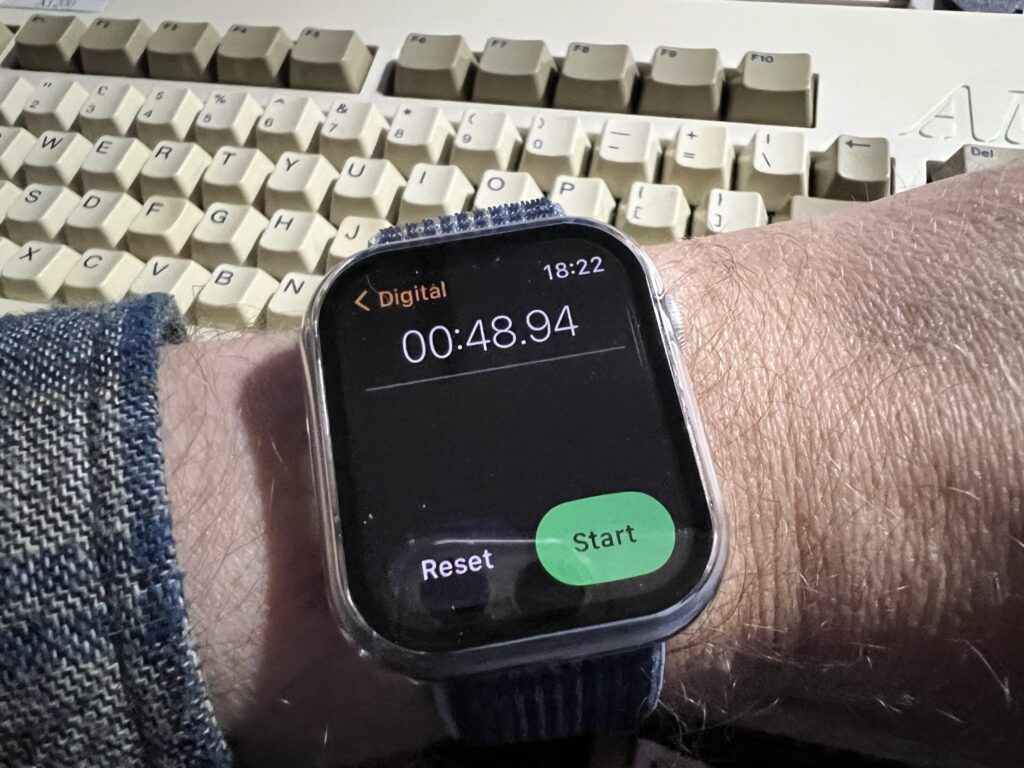
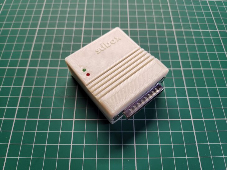
Guess who got an Apple Watch for Christmas and wanted an excuse to use it?
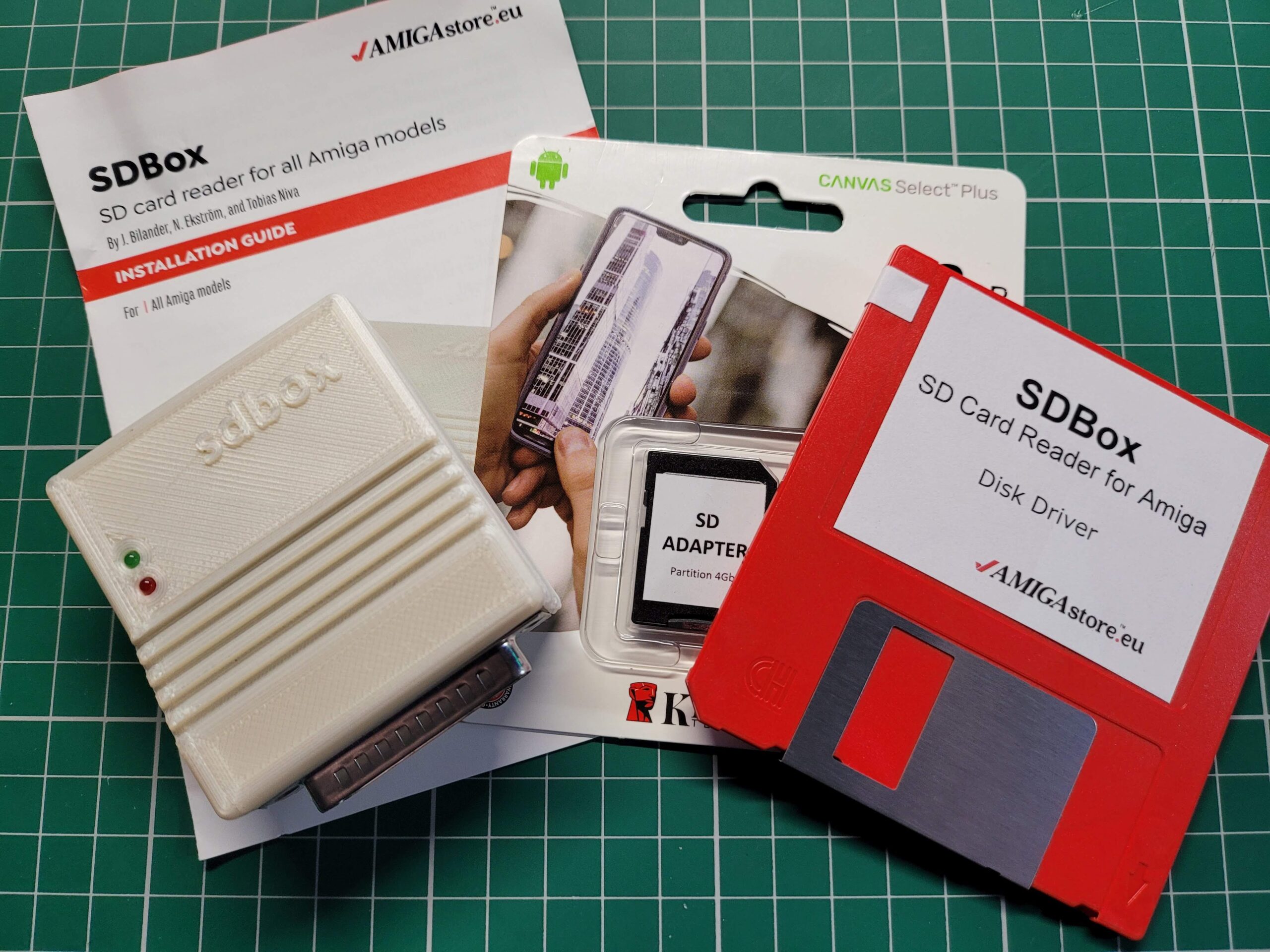
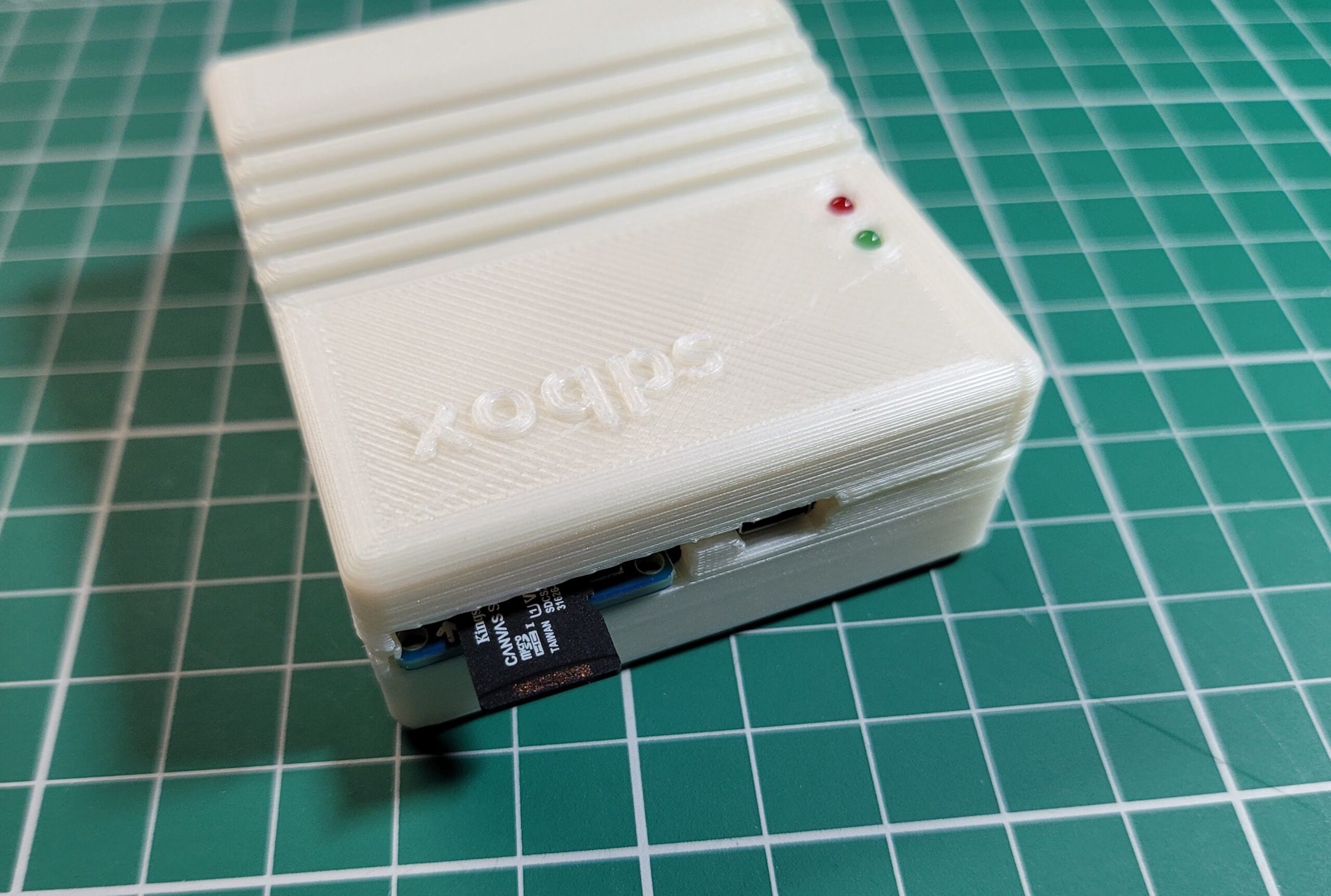
For the sake of completeness I timed transferring the same file to an SD card using my SDBox device. That took 26 seconds, so basically twice as fast as the SMB share. However that isn’t accessible to the PC when it’s in the Amiga and vice versa, plus there’s the faffing around swapping the card from one reader to another so probably slower all things considered.
In reality for most regular sized Amiga files you probably won’t notice much of a lag in moving them around at all. An ADF image takes 13 seconds to transfer which is perfectly acceptable in my view. Besides, these timings are missing the point really. The sheer convenience of having a drive that you can use to share files ‘on the fly’ between your PC(s) and Amiga(s) trumps any small time penalties experienced whilst doing so.
I have access to floppy disks, Zip disks, CDR’s, SD cards, PCMCIA CF cards but I choose to use the SMB Shared Folder most of the time when transferring stuff to and from my Amiga. It just works and its really convenient. That should speak volumes about the usefulness of such a setup so if you have the resources available, go for it!
Anyway I hope this article helps a few at least a few people access a network share on the Amiga. Let me know of your successes (or fails!) by leaving a reply below.